2001 INFINITI QX4 IDX
[x] Cancel search: IDXPage 1948 of 2395
RHA065DD
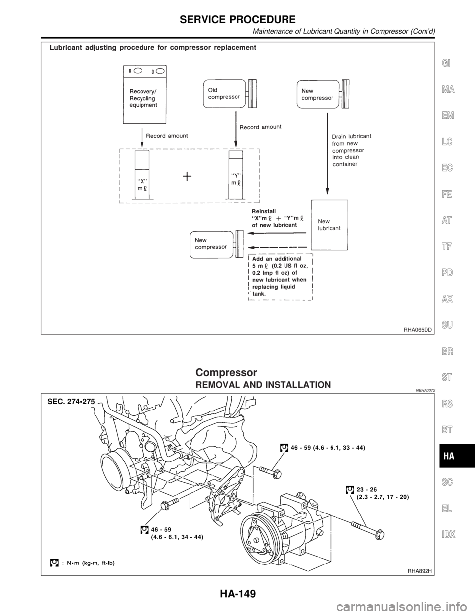
Compressor
REMOVAL AND INSTALLATIONNBHA0072
RHA892H
GI
MA
EM
LC
EC
FE
AT
TF
PD
AX
SU
BR
ST
RS
BT
SC
EL
IDX
SERVICE PROCEDURE
Maintenance of Lubricant Quantity in Compressor (Cont'd)
HA-149
Page 1950 of 2395
RHA138E
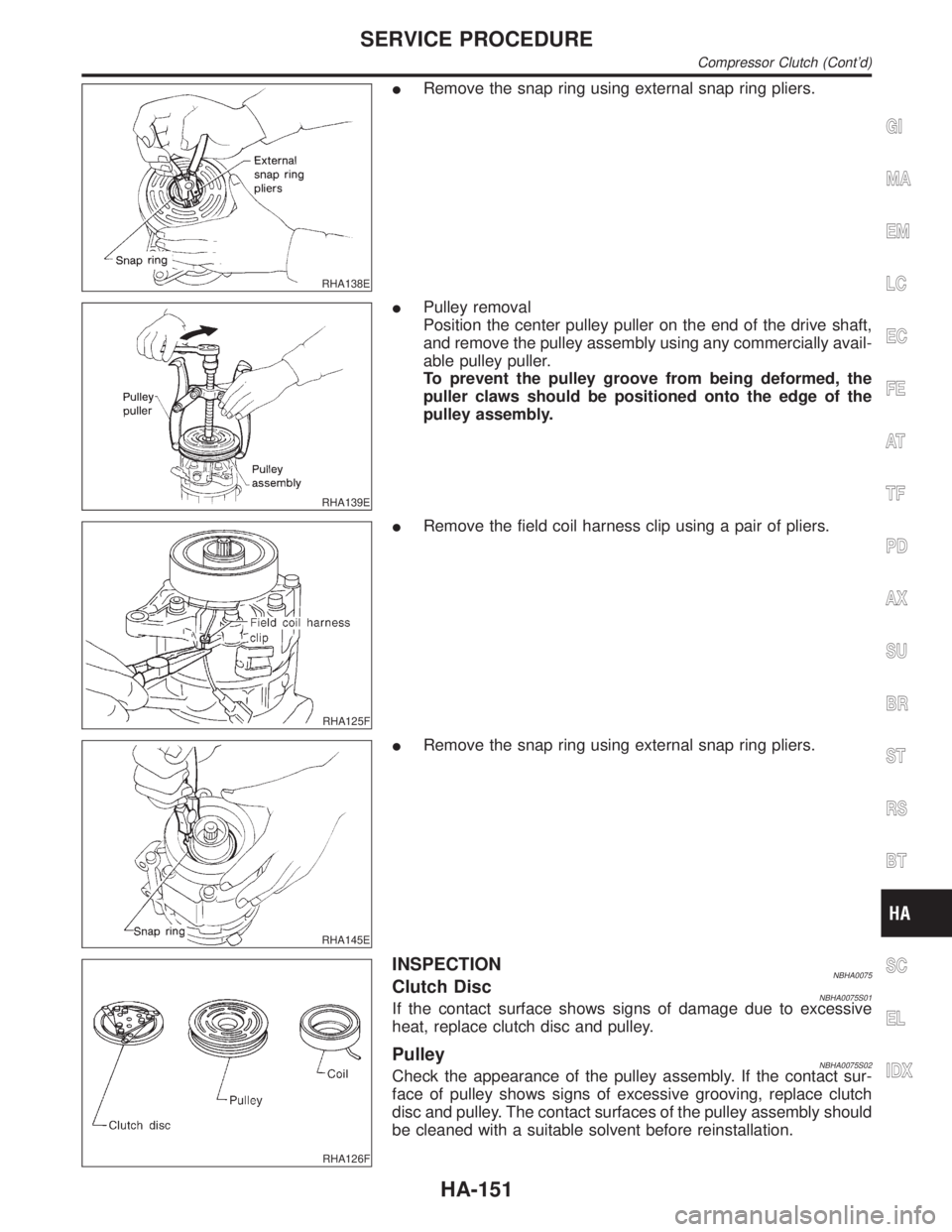
IRemove the snap ring using external snap ring pliers.
RHA139E
IPulley removal
Position the center pulley puller on the end of the drive shaft,
and remove the pulley assembly using any commercially avail-
able pulley puller.
To prevent the pulley groove from being deformed, the
puller claws should be positioned onto the edge of the
pulley assembly.
RHA125F
IRemove the field coil harness clip using a pair of pliers.
RHA145E
IRemove the snap ring using external snap ring pliers.
RHA126F
INSPECTIONNBHA0075Clutch DiscNBHA0075S01If the contact surface shows signs of damage due to excessive
heat, replace clutch disc and pulley.
PulleyNBHA0075S02Check the appearance of the pulley assembly. If the contact sur-
face of pulley shows signs of excessive grooving, replace clutch
disc and pulley. The contact surfaces of the pulley assembly should
be cleaned with a suitable solvent before reinstallation.
GI
MA
EM
LC
EC
FE
AT
TF
PD
AX
SU
BR
ST
RS
BT
SC
EL
IDX
SERVICE PROCEDURE
Compressor Clutch (Cont'd)
HA-151
Page 1952 of 2395
RHA087E
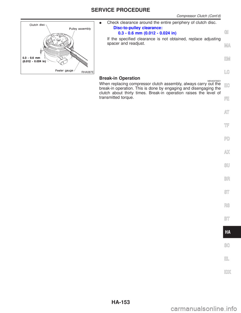
ICheck clearance around the entire periphery of clutch disc.
Disc-to-pulley clearance:
0.3 - 0.6 mm (0.012 - 0.024 in)
If the specified clearance is not obtained, replace adjusting
spacer and readjust.
Break-in OperationNBHA0076S01When replacing compressor clutch assembly, always carry out the
break-in operation. This is done by engaging and disengaging the
clutch about thirty times. Break-in operation raises the level of
transmitted torque.
GI
MA
EM
LC
EC
FE
AT
TF
PD
AX
SU
BR
ST
RS
BT
SC
EL
IDX
SERVICE PROCEDURE
Compressor Clutch (Cont'd)
HA-153
Page 1954 of 2395
CHECKING FOR REFRIGERANT LEAKS=NBHA0078IPerform a visual inspection of all refrigeration parts, fittings,
hoses and components for signs of A/C lubricant leakage,
damage and corrosion. A/C lubricant leakage may indicate an
area of refrigerant leakage. Allow extra inspection time in these
areas when using either an electronic refrigerant leak detector
or fluorescent dye leak detector.
IIf dye is observed, confirm the leak with an electronic refriger-
ant leak detector. It is possible a prior leak was repaired and
not properly cleaned.
IWhen searching for leaks, do not stop when one leak is found
but continue to check for additional leaks at all system compo-
nents and connections.
IWhen searching for refrigerant leaks using an electronic leak
detector, move the probe along the suspected leak area at 1
to 2 inches per second and no further than 1/4 inch from the
component.
NOTE:
Moving the electronic leak detector probe slower and closer to
the suspected leak area will improve the chances of finding a
leak.
CHECKING SYSTEM FOR LEAKS USING THE
FLUORESCENT LEAK DETECTOR
NBHA01161. Check A/C system for leaks using the UV lamp and safety
glasses (J-42220) in a low sunlight area (area without windows
preferable). Illuminate all components, fittings and lines. The
dye will appear as a bright green/yellow area at the point of
leakage. Fluorescent dye observed at the evaporator drain
opening indicates an evaporator core assembly (tubes, core or
TXV) leak.
2. If the suspected area is difficult to see, use an adjustable mir-
ror or wipe the area with a clean shop rag or cloth, then check
the cloth with the UV lamp for dye residue.
3. After the leak is repaired, remove any residual dye using dye
cleaner (J-43872) to prevent future misdiagnosis.
4. Perform a system performance check and verify the leak repair
with an approved electronic refrigerant leak detector.
NOTE:
IOther gases in the work area or substances on the A/C
components, for example, anti-freeze, windshield washer
fluid, solvents and lubricants, may falsely trigger the leak
detector. Make sure the surfaces to be checked are clean.
Clean with a dry cloth or blow off with shop air.
IDo not allow the sensor tip of the detector to contact with
any substance. This can also cause false readings and
may damage the detector.
DYE INJECTIONNBHA0117(This procedure is only necessary when re-charging the system or
when the compressor has seized and was replaced.)
1. Check A/C system static (at rest) Pressure. Pressure must be
at least 345 kPa (50 psi).
2. Pour one bottle (1/4 ounce /7.4 cc) of the A/C refrigerant dye
into the injector tool (J-41459).
3. Connect the injector tool to the A/C LOW PRESSURE side
service fitting.
4. Start engine and switch A/C ON.
GI
MA
EM
LC
EC
FE
AT
TF
PD
AX
SU
BR
ST
RS
BT
SC
EL
IDX
SERVICE PROCEDURE
Refrigerant Lines (Cont'd)
HA-155
Page 1956 of 2395
SHA708EA
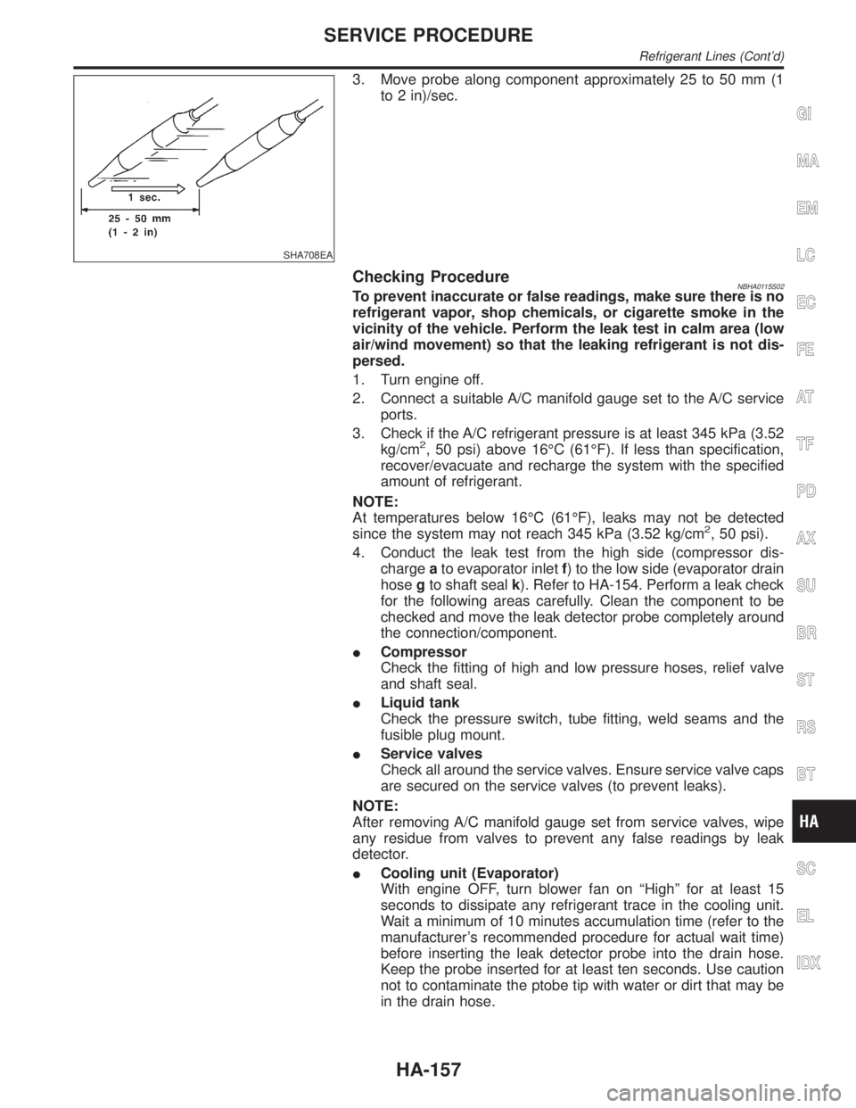
3. Move probe along component approximately 25 to 50 mm (1
to 2 in)/sec.
Checking ProcedureNBHA0115S02To prevent inaccurate or false readings, make sure there is no
refrigerant vapor, shop chemicals, or cigarette smoke in the
vicinity of the vehicle. Perform the leak test in calm area (low
air/wind movement) so that the leaking refrigerant is not dis-
persed.
1. Turn engine off.
2. Connect a suitable A/C manifold gauge set to the A/C service
ports.
3. Check if the A/C refrigerant pressure is at least 345 kPa (3.52
kg/cm
2, 50 psi) above 16ÉC (61ÉF). If less than specification,
recover/evacuate and recharge the system with the specified
amount of refrigerant.
NOTE:
At temperatures below 16ÉC (61ÉF), leaks may not be detected
since the system may not reach 345 kPa (3.52 kg/cm
2, 50 psi).
4. Conduct the leak test from the high side (compressor dis-
chargeato evaporator inletf) to the low side (evaporator drain
hosegto shaft sealk). Refer to HA-154. Perform a leak check
for the following areas carefully. Clean the component to be
checked and move the leak detector probe completely around
the connection/component.
ICompressor
Check the fitting of high and low pressure hoses, relief valve
and shaft seal.
ILiquid tank
Check the pressure switch, tube fitting, weld seams and the
fusible plug mount.
IService valves
Check all around the service valves. Ensure service valve caps
are secured on the service valves (to prevent leaks).
NOTE:
After removing A/C manifold gauge set from service valves, wipe
any residue from valves to prevent any false readings by leak
detector.
ICooling unit (Evaporator)
With engine OFF, turn blower fan on ªHighº for at least 15
seconds to dissipate any refrigerant trace in the cooling unit.
Wait a minimum of 10 minutes accumulation time (refer to the
manufacturer's recommended procedure for actual wait time)
before inserting the leak detector probe into the drain hose.
Keep the probe inserted for at least ten seconds. Use caution
not to contaminate the ptobe tip with water or dirt that may be
in the drain hose.
GI
MA
EM
LC
EC
FE
AT
TF
PD
AX
SU
BR
ST
RS
BT
SC
EL
IDX
SERVICE PROCEDURE
Refrigerant Lines (Cont'd)
HA-157
Page 1958 of 2395
Belt
TENSION ADJUSTMENTNBHA0079IRefer to MA-13, ªChecking Drive Beltsº.
RHA042G
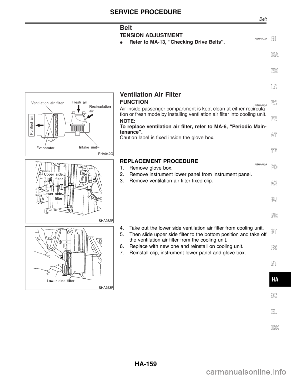
Ventilation Air Filter
FUNCTIONNBHA0108Air inside passenger compartment is kept clean at either recircula-
tion or fresh mode by installing ventilation air filter into cooling unit.
NOTE:
To replace ventilation air filter, refer to MA-6, ªPeriodic Main-
tenanceº.
Caution label is fixed inside the glove box.
SHA252F
REPLACEMENT PROCEDURENBHA01091. Remove glove box.
2. Remove instrument lower panel from instrument panel.
3. Remove ventilation air filter fixed clip.
SHA253F
4. Take out the lower side ventilation air filter from cooling unit.
5. Then slide upper side filter to the bottom position and take off
the ventilation air filter from the cooling unit.
6. Replace with new one and reinstall on cooling unit.
7. Reinstall clip, instrument lower panel and glove box.
GI
MA
EM
LC
EC
FE
AT
TF
PD
AX
SU
BR
ST
RS
BT
SC
EL
IDX
SERVICE PROCEDURE
Belt
HA-159
Page 1960 of 2395

ALPHABETICAL INDEX
SECTION
IDX
GI
MA
EM
LC
EC
FE
AT
TF
PD
AX
SU
BR
ST
RS
BT
HA
SC
EL
Page 1961 of 2395
A
AAC/V - Wiring diagram ...............................EC-425
ABS - Wiring diagram ....................................BR-37
ABS sensor rotor ........................................AX-6, 19
Absolute pressure sensor ............................EC-158
A/C air flow .....................................................HA-25
A/C component layout ....................................HA-19
A/C compressor clutch removal and
installation .................................................HA-150
A/C compressor precaution..............................HA-6
A/C compressor special service tool..............HA-10
A/C control operation (auto A/C) ....................HA-23
A/C diagnostic work flow (auto A/C) ..............HA-65
A/C HFC134a (R134a) system
precaution .....................................................HA-2
A/C HFC134a (R134a) system service
procedure ..................................................HA-144
A/C HFC134a (R134a) system service
tools.............................................................HA-11
A/C HFC134a system service equip-
ment precaution ............................................HA-7
A/C lubricant (R134a)...................................HA-146
A/C operational check ....................................HA-66
A/C performance chart .................................HA-116
A/C performance test diagnoses ..................HA-114
A/C relay .......................................................HA-110
A/C self-diagnoses (auto A/C)........................HA-44
A/C service data specification ......................HA-160
A/C system description (auto A/C) .................HA-23
A/C trouble diagnoses (auto A/C) ..................HA-27
A/C, A - Wiring diagram ...........................HA-31, 36
Accelerator control system ...............................FE-3
Accelerator wire adjustment .............................FE-3
Actuator lever (Transfer) ...............................TF-120
Air bag ............................................................RS-10
Air bag disposal..............................................RS-22
Air bag precautions ...........................................GI-3
Air bleeding for brake system ..........................BR-8
Air cleaner filter replacement .........................MA-17
Air conditioner cut control ..............................EC-31
Air flow meter - See Mass air flow
sensor .......................................................EC-150
Air mix door control linkage adjustment.........HA-85
Air mix. door motor ................................HA-82, 141
Air spoiler, rear................................................BT-35
All - mode 4WD system ..................................TF-10
Alternator ........................................................SC-28
Ambient sensor ............................................HA-129
Angular tightening application..........................EM-3
Antenna - See Power antenna .....................EL-169
Anti-lock brake system - Wiring
diagram .......................................................BR-37
AP/SEN - Wiring diagram ............................EC-160
ASCD (automatic speed control device) ......EL-221
ASCD - Wiring diagram ................................EL-225
A/T - Wiring diagram - AT - FTS ...................AT-107
A/T - Wiring diagram - AT - MAIN ...................AT-96
A/T - Wiring diagram - AT - PNP/SW............AT-101A/T - Wiring diagram - AT - VSS A/T ............AT-113
A/T control ....................................................EC-440
A/T diagnosis communication line................EC-603
A/T fluid temperature sensor .........................AT-110
A/T self-diagnoses...........................................AT-46
A/T shift lock system .....................................AT-265
A/T shift lock system - Wiring diagram .........AT-266
A/T trouble diagnoses .....................................AT-53
A/T Wiring diagram - AT - ENG SS...............AT-117
A/T Wiring diagram AT - 1ST ........................AT-123
A/T Wiring diagram AT - 2ND .......................AT-129
A/T Wiring diagram AT - 3RD .......................AT-135
A/T Wiring diagram AT - 4TH ........................AT-142
A/T Wiring diagram AT - BA/FTS ..................AT-192
A/T Wiring diagram AT - LPSV .....................AT-164
A/T Wiring diagram AT - NONDTC ...............AT-215
A/T Wiring diagram AT - OVRCSV ...............AT-187
A/T Wiring diagram AT - SSV/A ....................AT-169
A/T Wiring diagram AT - SSV/B ....................AT-173
A/T Wiring diagram AT - TCCSIG .................AT-156
A/T Wiring diagram AT - TCV .......................AT-150
A/T Wiring diagram AT - TPS........................AT-179
A/T Wiring diagram AT - VSSMTR................AT-199
AT/C - Wiring diagram ..................................EC-442
ATP switch.....................................................TF-112
ATP warning lamp .........................................TF-102
Audio .............................................................EL-160
AUDIO - Wiring diagram ...............................EL-162
Audio and A/C control removal and
installation - See Instrument panel .............BT-21
AUT/DP - Wiring diagram .............................EL-191
Auto air conditioner - Wiring diagram ......HA-31, 36
Automatic amplifier...................................HA-40, 72
Automatic drive positioner ............................EL-186
Automatic speed control system - See
ASCD ........................................................EL-221
Automatic transmission fluid
replacement ................................................MA-21
Automatic transmission number ......................GI-43
Auxiliary air control (AAC) valve ..................EC-422
Axle housing (rear) .........................................AX-19
B
Back door ........................................................BT-15
Back door opener - See Back door ................BT-15
Back door trim.................................................BT-34
Back-up lamp ..................................................EL-69
BACK/L - Wiring diagram................................EL-69
Ball joint (front) ...............................................SU-12
Base idle air volume initialiging......................EC-57
Basic inspection ...........................................EC-101
Battery ..............................................................SC-4
Battery/Starting/Charging System
Tester ................................................SC-7, 12, 21
Blower motor ..................................................HA-95
Body alignment ...............................................BT-57
Brake booster .................................................BR-19
Brake control valve (Proportioning
valve)...........................................................BR-11
ALPHABETICAL INDEX
IDX-2