2001 INFINITI QX4 IDX
[x] Cancel search: IDXPage 1638 of 2395
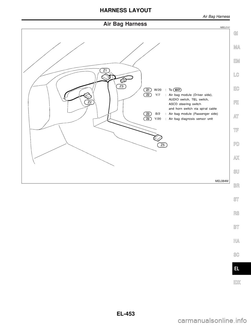
Air Bag HarnessNBEL0141
MEL084M
GI
MA
EM
LC
EC
FE
AT
TF
PD
AX
SU
BR
ST
RS
BT
HA
SC
IDX
HARNESS LAYOUT
Air Bag Harness
EL-453
Page 1640 of 2395
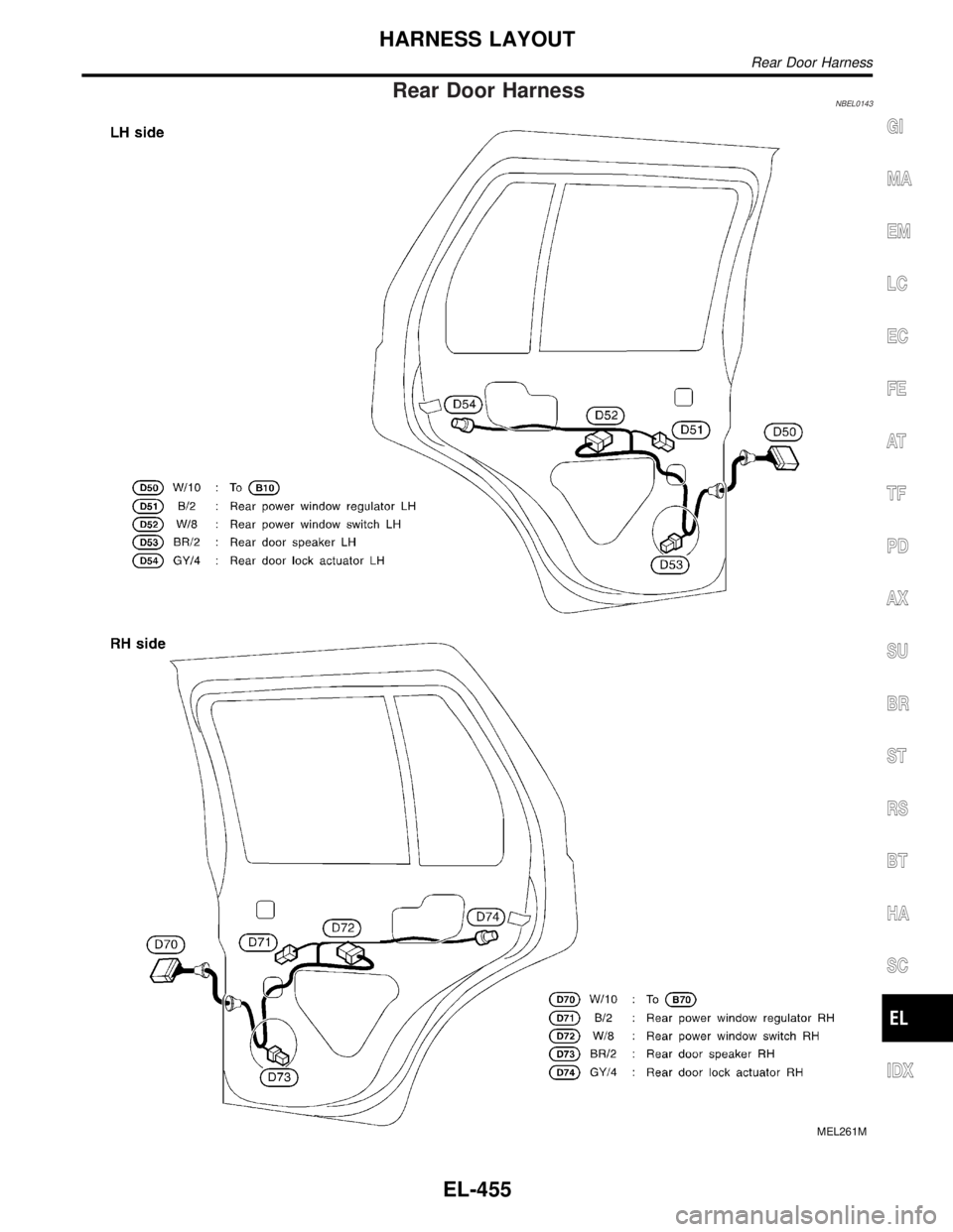
Rear Door HarnessNBEL0143
MEL261M
GI
MA
EM
LC
EC
FE
AT
TF
PD
AX
SU
BR
ST
RS
BT
HA
SC
IDX
HARNESS LAYOUT
Rear Door Harness
EL-455
Page 1642 of 2395
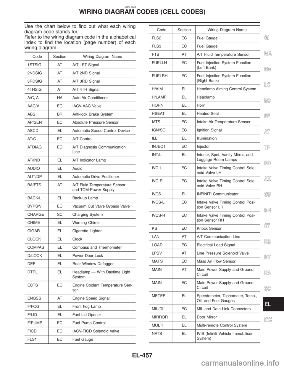
NBEL0145
Use the chart below to find out what each wiring
diagram code stands for.
Refer to the wiring diagram code in the alphabetical
index to find the location (page number) of each
wiring diagram.
Code Section Wiring Diagram Name
1STSIG AT A/T 1ST Signal
2NDSIG AT A/T 2ND Signal
3RDSIG AT A/T 3RD Signal
4THSIG AT A/T 4TH Signal
A/C, A HA Auto Air Conditioner
AAC/V EC IACV-AAC Valve
ABS BR Anti-lock Brake System
AP/SEN EC Absolute Pressure Sensor
ASCD EL Automatic Speed Control Device
AT/C EC A/T Control
ATDIAG EC A/T Diagnosis Communication
Line
AT/IND EL A/T Indicator Lamp
AUDIO EL Audio
AUT/DP EL Automatic Drive Positioner
BA/FTS AT A/T Fluid Temperature Sensor
and TCM Power Supply
BACK/L EL Back-up Lamp
BYPS/V EC Vacuum Cut Valve Bypass Valve
CHARGE SC Charging System
CHIME EL Warning Chime
CIGAR EL Cigarette Lighter
CLOCK EL Clock
COMPAS EL Compass and Thermometer
D/LOCK EL Power Door Lock
DEF EL Rear Window Defogger
DTRL EL Headlamp Ð With Daytime Light
System Ð
ECTS EC Engine Coolant Temperature Sen-
sor
ENGSS AT Engine Speed Signal
F/FOG EL Front Fog Lamp
F/LID EL Fuel Lid Opener
F/PUMP EC Fuel Pump Control
FICD EC IACV-FICD Solenoid Valve
FLS1 EC Fuel Gauge
Code Section Wiring Diagram Name
FLS2 EC Fuel Gauge
FLS3 EC Fuel Gauge
FTS AT A/T Fluid Temperature Sensor
FUELLH EC Fuel Injection System Function
(Left Bank)
FUELRH EC Fuel Injection System Function
(Right Bank)
H/AIM EL Headlamp Aiming Control System
H/LAMP EL Headlamp
HORN EL Horn
HSEAT EL Heated Seat
IATS EC Intake Air Temperature Sensor
IGN/SG EC Ignition Signal
ILL EL Illumination
INJECT EC Injector
INT/L EL Interior, Spot, Vanity Mirror, and
Luggage Room Lamps
IVC-L EC Intake Valve Timing Control Sole-
noid Valve LH
IVC-R EC Intake Valve Timing Control Sole-
noid Valve RH
IVCS EL INFINITI Communicator
IVCS-L EC Intake Valve Timing Control Posi-
tion Sensor LH
IVCS-R EC Intake Valve Timing Control Posi-
tion Sensor RH
KS EC Knock Sensor
LAN AT A/T Communication Line
LOAD EC Electrical Load Signal
LPSV AT Line Pressure Solenoid Valve
MAFS EC Mass Air Flow Sensor
MAIN AT Main Power Supply and Ground
Circuit
MAIN EC Main Power Supply and Ground
Circuit
METER EL Speedometer, Tachometer, Temp.,
Oil, and Fuel Gauges
MIL/DL EC MIL and Data Link Connectors
MIRROR EL Door Mirror
MULTI EL Multi-remote Control System
NATS EL IVIS (Infiniti Vehicle Immobiliser
System)
GI
MA
EM
LC
EC
FE
AT
TF
PD
AX
SU
BR
ST
RS
BT
HA
SC
IDX
WIRING DIAGRAM CODES (CELL CODES)
EL-457
Page 1644 of 2395
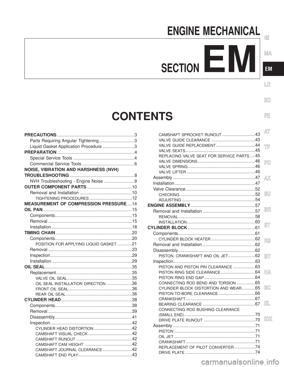
ENGINE MECHANICAL
SECTION
EM
CONTENTS
PRECAUTIONS...............................................................3
Parts Requiring Angular Tightening .............................3
Liquid Gasket Application Procedure ..........................3
PREPARATION...............................................................4
Special Service Tools ..................................................4
Commercial Service Tools ...........................................6
NOISE, VIBRATION AND HARSHNESS (NVH)
TROUBLESHOOTING.....................................................8
NVH Troubleshooting - Engine Noise .........................9
OUTER COMPONENT PARTS.....................................10
Removal and Installation ...........................................10
TIGHTENING PROCEDURES...................................12
MEASUREMENT OF COMPRESSION PRESSURE....14
OIL PAN.........................................................................15
Components...............................................................15
Removal .....................................................................15
Installation ..................................................................18
TIMING CHAIN..............................................................20
Components...............................................................20
POSITION FOR APPLYING LIQUID GASKET............21
Removal .....................................................................23
Inspection...................................................................29
Installation ..................................................................29
OIL SEAL.......................................................................35
Replacement ..............................................................35
VALVE OIL SEAL.....................................................35
OIL SEAL INSTALLATION DIRECTION.....................36
FRONT OIL SEAL....................................................36
REAR OIL SEAL......................................................36
CYLINDER HEAD..........................................................38
Components...............................................................38
Removal .....................................................................39
Disassembly...............................................................41
Inspection...................................................................42
CYLINDER HEAD DISTORTION...............................42
CAMSHAFT VISUAL CHECK....................................42
CAMSHAFT RUNOUT..............................................42
CAMSHAFT CAM HEIGHT.......................................42
CAMSHAFT JOURNAL CLEARANCE........................42
CAMSHAFT END PLAY............................................43
CAMSHAFT SPROCKET RUNOUT...........................43
VALVE GUIDE CLEARANCE....................................43
VALVE GUIDE REPLACEMENT................................44
VALVE SEATS.........................................................45
REPLACING VALVE SEAT FOR SERVICE PARTS....45
VALVE DIMENSIONS...............................................46
VALVE SPRING.......................................................46
VALVE LIFTER........................................................46
Assembly ...................................................................47
Installation ..................................................................47
Valve Clearance.........................................................52
CHECKING.............................................................52
ADJUSTING............................................................54
ENGINE ASSEMBLY.....................................................57
Removal and Installation ...........................................57
REMOVAL...............................................................58
INSTALLATION........................................................60
CYLINDER BLOCK.......................................................61
Components...............................................................61
CYLINDER BLOCK HEATER....................................62
Removal and Installation ...........................................62
Disassembly...............................................................62
PISTON, CRANKSHAFT AND OIL JET......................62
Inspection...................................................................63
PISTON AND PISTON PIN CLEARANCE..................63
PISTON RING SIDE CLEARANCE............................64
PISTON RING END GAP..........................................64
CONNECTING ROD BEND AND TORSION...............65
CYLINDER BLOCK DISTORTION AND WEAR...........65
PISTON-TO-BORE CLEARANCE..............................66
CRANKSHAFT.........................................................67
BEARING CLEARANCE...........................................67
CONNECTING ROD BUSHING CLEARANCE
(SMALL END)
..........................................................70
DRIVE PLATE RUNOUT..........................................70
Assembly ...................................................................71
PISTON..................................................................71
OIL JET..................................................................71
CRANKSHAFT.........................................................71
REPLACEMENT OF PILOT CONVERTER.................74
DRIVE PLATE.........................................................74
GI
MA
LC
EC
FE
AT
TF
PD
AX
SU
BR
ST
RS
BT
HA
SC
EL
IDX
Page 1646 of 2395
Parts Requiring Angular TighteningNBEM0001IUse an angle wrench for the final tightening of the following
engine parts:
a) Cylinder head bolts
b) Main bearing cap bolts
c) Connecting rod cap bolts
d) Crankshaft pulley bolt
IDo not use a torque value for final tightening.
IThe torque value for these parts are for a preliminary step.
IEnsure thread and seat surfaces are clean and coated with
engine oil.
SEM164F
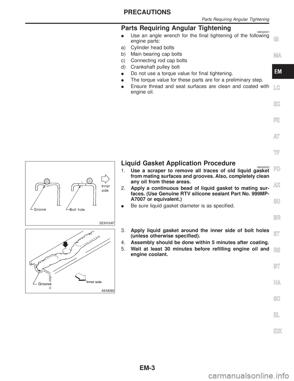
Liquid Gasket Application ProcedureNBEM00021.Use a scraper to remove all traces of old liquid gasket
from mating surfaces and grooves. Also, completely clean
any oil from these areas.
2.Apply a continuous bead of liquid gasket to mating sur-
faces. (Use Genuine RTV silicone sealant Part No. 999MP-
A7007 or equivalent.)
IBe sure liquid gasket diameter is as specified.
AEM080
3.Apply liquid gasket around the inner side of bolt holes
(unless otherwise specified).
4.Assembly should be done within 5 minutes after coating.
5.Wait at least 30 minutes before refilling engine oil and
engine coolant.
GI
MA
LC
EC
FE
AT
TF
PD
AX
SU
BR
ST
RS
BT
HA
SC
EL
IDX
PRECAUTIONS
Parts Requiring Angular Tightening
EM-3
Page 1648 of 2395
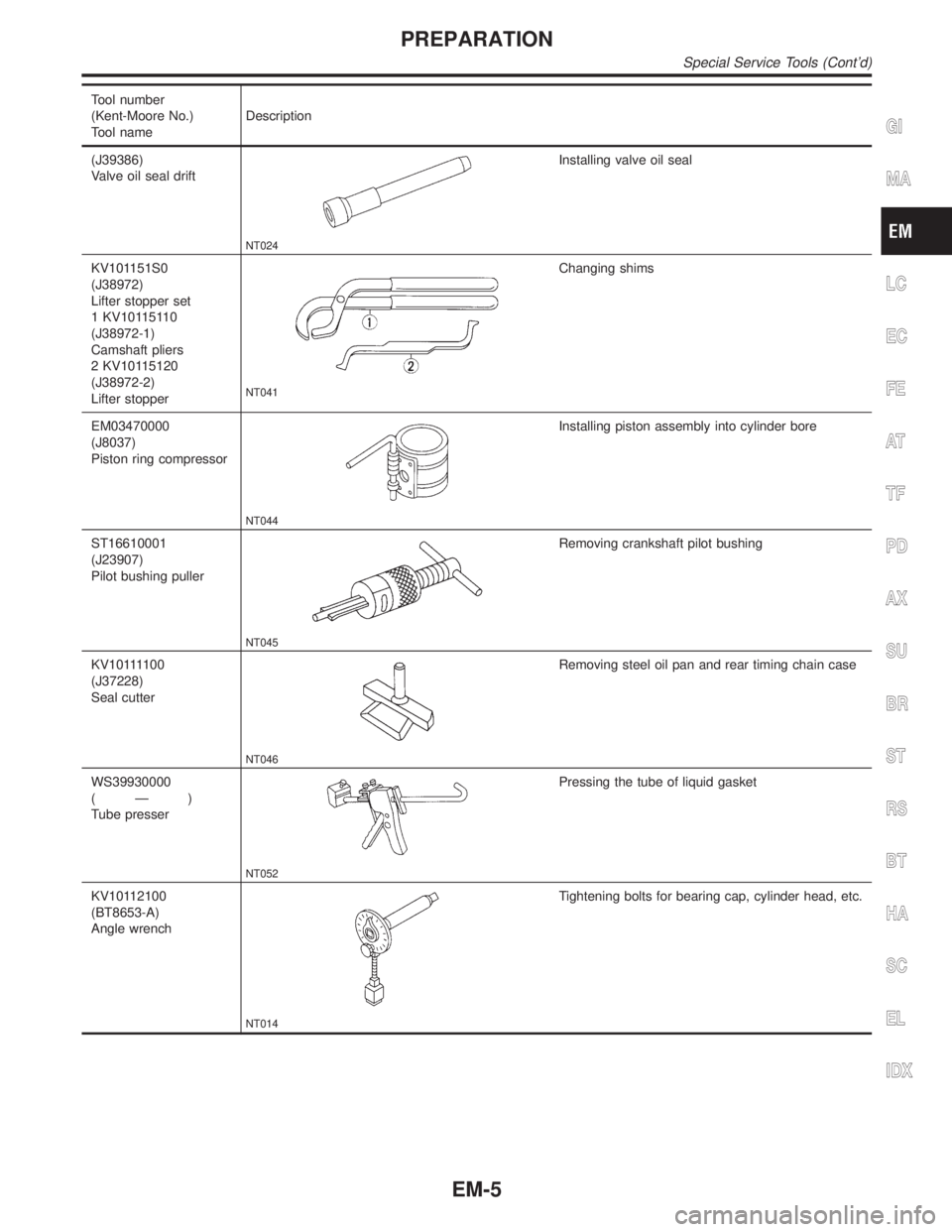
Tool number
(Kent-Moore No.)
Tool nameDescription
(J39386)
Valve oil seal drift
NT024
Installing valve oil seal
KV101151S0
(J38972)
Lifter stopper set
1 KV10115110
(J38972-1)
Camshaft pliers
2 KV10115120
(J38972-2)
Lifter stopper
NT041
Changing shims
EM03470000
(J8037)
Piston ring compressor
NT044
Installing piston assembly into cylinder bore
ST16610001
(J23907)
Pilot bushing puller
NT045
Removing crankshaft pilot bushing
KV101111 0 0
(J37228)
Seal cutter
NT046
Removing steel oil pan and rear timing chain case
WS39930000
(Ð)
Tube presser
NT052
Pressing the tube of liquid gasket
KV10112100
(BT8653-A)
Angle wrench
NT014
Tightening bolts for bearing cap, cylinder head, etc.
GI
MA
LC
EC
FE
AT
TF
PD
AX
SU
BR
ST
RS
BT
HA
SC
EL
IDX
PREPARATION
Special Service Tools (Cont'd)
EM-5
Page 1650 of 2395
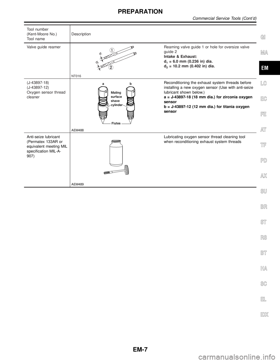
Tool number
(Kent-Moore No.)
Tool nameDescription
Valve guide reamer
NT016
Reaming valve guide 1 or hole for oversize valve
guide 2
Intake & Exhaust:
d
1= 6.0 mm (0.236 in) dia.
d
2= 10.2 mm (0.402 in) dia.
(J-43897-18)
(J-43897-12)
Oxygen sensor thread
cleaner
AEM488
Reconditioning the exhaust system threads before
installing a new oxygen sensor (Use with anti-seize
lubricant shown below.)
a = J-43897-18 (18 mm dia.) for zirconia oxygen
sensor
b = J-43897-12 (12 mm dia.) for titania oxygen
sensor
Anti-seize lubricant
(Permatex 133AR or
equivalent meeting MIL
specification MIL-A-
907)
AEM489
Lubricating oxygen sensor thread cleaning tool
when reconditioning exhaust system threads
GI
MA
LC
EC
FE
AT
TF
PD
AX
SU
BR
ST
RS
BT
HA
SC
EL
IDX
PREPARATION
Commercial Service Tools (Cont'd)
EM-7
Page 1652 of 2395
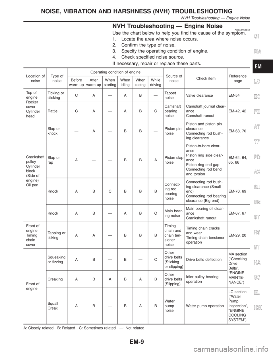
NVH Troubleshooting Ð Engine NoiseNBEM0005S01Use the chart below to help you find the cause of the symptom.
1. Locate the area where noise occurs.
2. Confirm the type of noise.
3. Specify the operating condition of engine.
4. Check specified noise source.
If necessary, repair or replace these parts.
Location of
noiseType of
noiseOperating condition of engine
Source of
noiseCheck itemReference
page Before
warm-upAfter
warm-upWhen
startingWhen
idlingWhen
racingWhile
driving
To p o f
engine
Rocker
cover
Cylinder
headTicking or
clickingC A ÐA BÐTappet
noiseValve clearance EM-54
Rattle C A Ð A B CCamshaft
bearing
noiseCamshaft journal clear-
ance
Camshaft runoutEM-42, 42
Crankshaft
pulley
Cylinder
block
(Side of
engine)
Oil panSlap or
knockÐ A ÐB BÐPiston pin
noisePiston and piston pin
clearance
Connecting rod bush-
ing clearanceEM-63, 70
Slap or
rapA ÐÐBBAPiston slap
noisePiston-to-bore clear-
ance
Piston ring side clear-
ance
Piston ring end gap
Connecting rod bend
and torsionEM-64, 64,
65, 66
Knock A B C B B BConnect-
ing rod
bearing
noiseConnecting rod bush-
ing clearance (Small
end)
Connecting rod bearing
clearance (Big end)EM-70, 69
Knock A B Ð A B CMain bear-
ing noiseMain bearing oil clear-
ance
Crankshaft runoutEM-67, 67
Front of
engine
Timing
chain
coverTapping or
tickingA A ÐBBBTiming
chain and
chain ten-
sioner
noiseTiming chain cracks
and wear
Timing chain tensioner
operationEM-29, 20
Front of
engineSqueaking
or fizzingA B ÐBÐCOther
drive belts
(Sticking
or slipping)Drive belts deflectionMA section
(ªChecking
Drive
Beltsº,
ªENGINE
MAINTE-
NANCEº) Creaking A BABABOther
drive belts
(Slipping)Idler pulley bearing
operation
Squall
CreakA B ÐBABWater
pump
noiseWater pump operationLC section
(ªWater
Pump
Inspectionº,
ªENGINE
COOLING
SYSTEMº)
A: Closely related B: Related C: Sometimes related Ð: Not related
GI
MA
LC
EC
FE
AT
TF
PD
AX
SU
BR
ST
RS
BT
HA
SC
EL
IDX
NOISE, VIBRATION AND HARSHNESS (NVH) TROUBLESHOOTING
NVH Troubleshooting Ð Engine Noise
EM-9