2001 DODGE TOWN AND COUNTRY transmission oil
[x] Cancel search: transmission oilPage 1416 of 2321
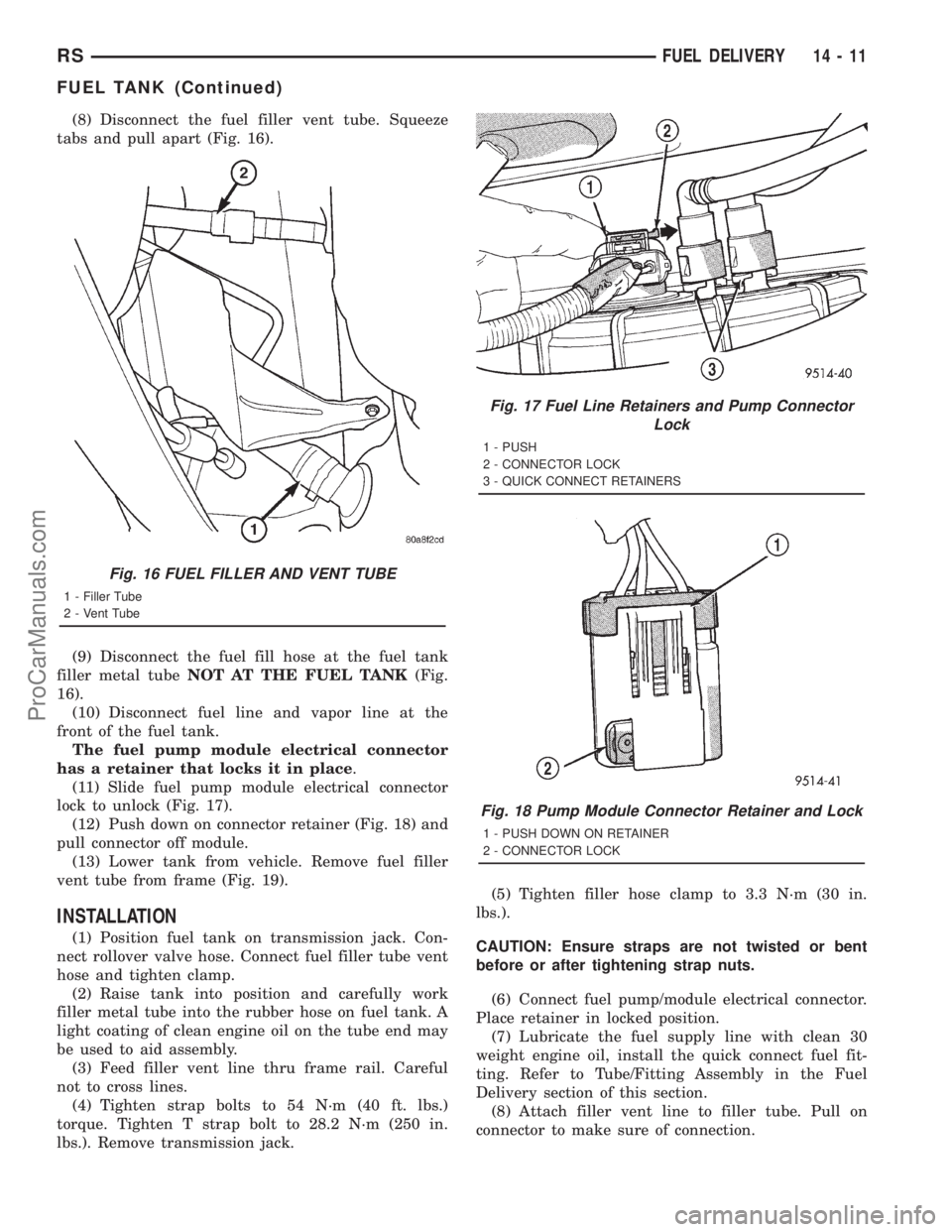
(8) Disconnect the fuel filler vent tube. Squeeze
tabs and pull apart (Fig. 16).
(9) Disconnect the fuel fill hose at the fuel tank
filler metal tubeNOT AT THE FUEL TANK(Fig.
16).
(10) Disconnect fuel line and vapor line at the
front of the fuel tank.
The fuel pump module electrical connector
has a retainer that locks it in place.
(11) Slide fuel pump module electrical connector
lock to unlock (Fig. 17).
(12) Push down on connector retainer (Fig. 18) and
pull connector off module.
(13) Lower tank from vehicle. Remove fuel filler
vent tube from frame (Fig. 19).
INSTALLATION
(1) Position fuel tank on transmission jack. Con-
nect rollover valve hose. Connect fuel filler tube vent
hose and tighten clamp.
(2) Raise tank into position and carefully work
filler metal tube into the rubber hose on fuel tank. A
light coating of clean engine oil on the tube end may
be used to aid assembly.
(3) Feed filler vent line thru frame rail. Careful
not to cross lines.
(4) Tighten strap bolts to 54 N´m (40 ft. lbs.)
torque. Tighten T strap bolt to 28.2 N´m (250 in.
lbs.). Remove transmission jack.(5) Tighten filler hose clamp to 3.3 N´m (30 in.
lbs.).
CAUTION: Ensure straps are not twisted or bent
before or after tightening strap nuts.
(6) Connect fuel pump/module electrical connector.
Place retainer in locked position.
(7) Lubricate the fuel supply line with clean 30
weight engine oil, install the quick connect fuel fit-
ting. Refer to Tube/Fitting Assembly in the Fuel
Delivery section of this section.
(8) Attach filler vent line to filler tube. Pull on
connector to make sure of connection.
Fig. 16 FUEL FILLER AND VENT TUBE
1 - Filler Tube
2 - Vent Tube
Fig. 17 Fuel Line Retainers and Pump Connector
Lock
1 - PUSH
2 - CONNECTOR LOCK
3 - QUICK CONNECT RETAINERS
Fig. 18 Pump Module Connector Retainer and Lock
1 - PUSH DOWN ON RETAINER
2 - CONNECTOR LOCK
RSFUEL DELIVERY14-11
FUEL TANK (Continued)
ProCarManuals.com
Page 1475 of 2321
ing gear. This travel pushes and pulls the tie rods to
change the direction of the vehicle's front wheels.
Power assist steering provided by the power steer-
ing pump is controlled by an open center, rotary type
control valve which directs oil from the pump to
either side of the integral rack piston upon demand.
Road feel is controlled by the diameter of a torsion
bar which initially steers the vehicle. As required
steering effort increases, as in a turn, the torsion bar
twists, causing relative rotary motion between the
rotary valve body and the valve spool. This move-
ment directs oil behind the integral rack piston
which, in turn, builds up hydraulic pressure and
assists in the turning effort.
Manual steering control of the vehicle can be main-
tained if power steering assist is lost. However,
under this condition, steering effort is significantly
increased.
SERVICE WARNINGS AND CAUTIONS
WARNING: POWER STEERING FLUID, ENGINE
PARTS AND EXHAUST SYSTEM MAY BE
EXTREMELY HOT IF ENGINE HAS BEEN RUNNING.
DO NOT START ENGINE WITH ANY LOOSE OR DIS-
CONNECTED HOSES. DO NOT ALLOW HOSES TO
TOUCH HOT EXHAUST MANIFOLD OR CATALYST.
WARNING: FLUID LEVEL SHOULD BE CHECKED
WITH THE ENGINE OFF TO PREVENT PERSONAL
INJURY FROM MOVING PARTS.
CAUTION: When the system is open, cap all open
ends of the hoses, power steering pump fittings or
power steering gear ports to prevent entry of for-
eign material into the components.
REMOVAL - GEAR
CAUTION: Positioning the steering column in the
locked position will prevent the clockspring from
being accidentally over-extended when the steering
column is disconnected from the intermediate
steering coupler.
(1) Remove cap from power steering fluid reser-
voir.
(2) Using a siphon pump, remove as much fluid as
possible from the power steering fluid reservoir.
(3) With the ignition key in the locked position
turn the steering wheel to the left until the steering
wheel is in the locked position.
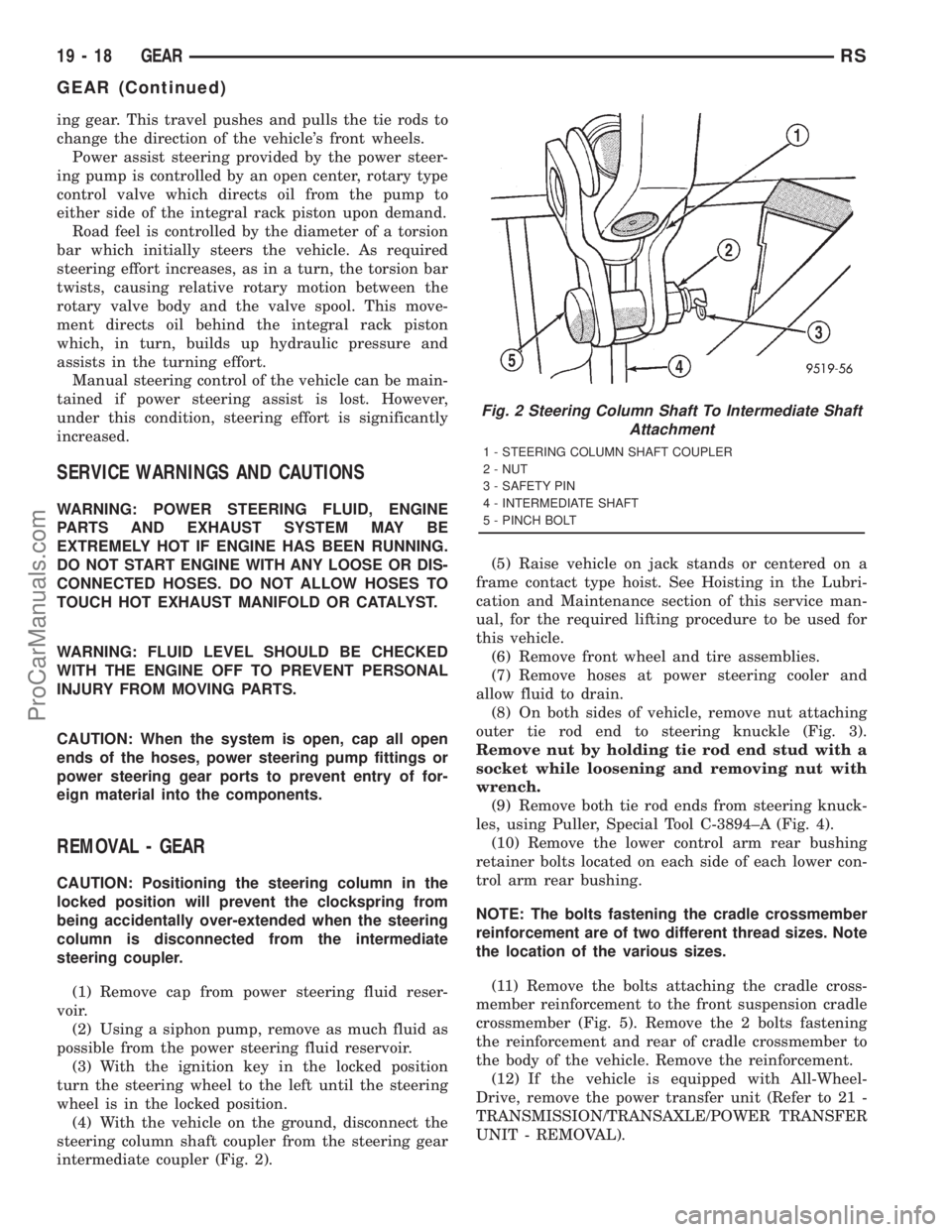
(4) With the vehicle on the ground, disconnect the
steering column shaft coupler from the steering gear
intermediate coupler (Fig. 2).(5) Raise vehicle on jack stands or centered on a
frame contact type hoist. See Hoisting in the Lubri-
cation and Maintenance section of this service man-
ual, for the required lifting procedure to be used for
this vehicle.
(6) Remove front wheel and tire assemblies.
(7) Remove hoses at power steering cooler and
allow fluid to drain.
(8) On both sides of vehicle, remove nut attaching
outer tie rod end to steering knuckle (Fig. 3).
Remove nut by holding tie rod end stud with a
socket while loosening and removing nut with
wrench.
(9) Remove both tie rod ends from steering knuck-
les, using Puller, Special Tool C-3894±A (Fig. 4).
(10) Remove the lower control arm rear bushing
retainer bolts located on each side of each lower con-
trol arm rear bushing.
NOTE: The bolts fastening the cradle crossmember
reinforcement are of two different thread sizes. Note
the location of the various sizes.
(11) Remove the bolts attaching the cradle cross-
member reinforcement to the front suspension cradle
crossmember (Fig. 5). Remove the 2 bolts fastening
the reinforcement and rear of cradle crossmember to
the body of the vehicle. Remove the reinforcement.
(12) If the vehicle is equipped with All-Wheel-
Drive, remove the power transfer unit (Refer to 21 -
TRANSMISSION/TRANSAXLE/POWER TRANSFER
UNIT - REMOVAL).
Fig. 2 Steering Column Shaft To Intermediate Shaft
Attachment
1 - STEERING COLUMN SHAFT COUPLER
2 - NUT
3 - SAFETY PIN
4 - INTERMEDIATE SHAFT
5 - PINCH BOLT
19 - 18 GEARRS
GEAR (Continued)
ProCarManuals.com
Page 1498 of 2321
TRANSMISSION/TRANSAXLE
TABLE OF CONTENTS
page page
POWER TRANSFER UNIT...................1
AUTOMATIC - 31TH.......................21AUTOMATIC - 41TE......................158
POWER TRANSFER UNIT
TABLE OF CONTENTS
page page
POWER TRANSFER UNIT
DESCRIPTION............................1
OPERATION.............................3
DIAGNOSIS AND TESTING..................3
SEAL IDENTIFICATION...................3
FLUID LEAK DIAGNOSIS..................3
STANDARD PROCEDURE...................4
FLUID LEVEL INSPECTION................4
PTU FLUID CHANGE.....................4
REMOVAL...............................5
INSTALLATION............................6
ADJUSTMENTS...........................7
SPECIFICATIONS.........................7
SPECIAL TOOLS..........................8
DIFFERENTIAL CARRIER SEAL
REMOVAL...............................9
INSTALLATION............................9
END COVER BALL BEARING
REMOVAL...............................9
INSTALLATION...........................10
END COVER SEAL
REMOVAL..............................11INSTALLATION...........................11
HALF SHAFT INNER SEAL
REMOVAL..............................12
INSTALLATION...........................12
INPUT SHAFT COVER SEAL
REMOVAL..............................13
INSTALLATION...........................14
INPUT SHAFT END SEAL
REMOVAL..............................16
INSTALLATION...........................16
INPUT SHAFT SEAL
REMOVAL..............................17
INSTALLATION...........................18
OUTER HALF SHAFT SEAL
REMOVAL..............................18
INSTALLATION...........................19
REAR COVER O-RING
REMOVAL..............................20
INSTALLATION...........................20
POWER TRANSFER UNIT
DESCRIPTION
The Power Transfer Unit (P.T.U.) is attached to a
modified automatic transaxle case where the right
half shaft extension housing would normally be
located.
The Power Transfer Unit is sealed from the trans-
axle and has its own oil sump. The Unit uses
Moparž SAE 80W-90 Gear and Axle Lubricant (MS-
9020) and holds 1.15 liters (1.22 quarts).Service of the Power Transfer Unit is limited to:
²Fluid Change
²Seals
²Gaskets
²One ball bearing
²Output flange
If the ring gear and pinion, any tapered roller
bearings, case, covers, or pinion carrier fail the entire
unit must be replaced.
RSTRANSMISSION/TRANSAXLE21-1
ProCarManuals.com
Page 1501 of 2321
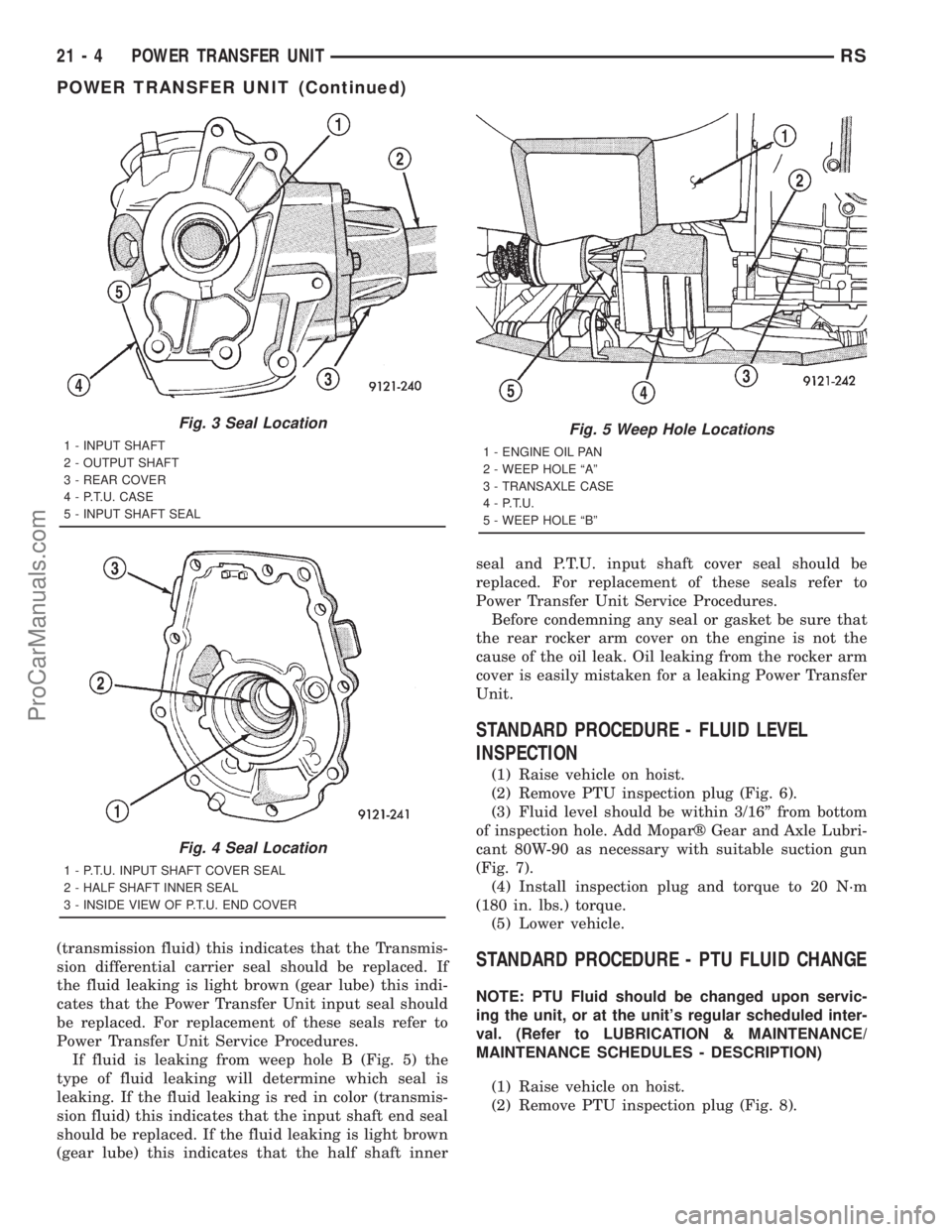
(transmission fluid) this indicates that the Transmis-
sion differential carrier seal should be replaced. If
the fluid leaking is light brown (gear lube) this indi-
cates that the Power Transfer Unit input seal should
be replaced. For replacement of these seals refer to
Power Transfer Unit Service Procedures.
If fluid is leaking from weep hole B (Fig. 5) the
type of fluid leaking will determine which seal is
leaking. If the fluid leaking is red in color (transmis-
sion fluid) this indicates that the input shaft end seal
should be replaced. If the fluid leaking is light brown
(gear lube) this indicates that the half shaft innerseal and P.T.U. input shaft cover seal should be
replaced. For replacement of these seals refer to
Power Transfer Unit Service Procedures.
Before condemning any seal or gasket be sure that
the rear rocker arm cover on the engine is not the
cause of the oil leak. Oil leaking from the rocker arm
cover is easily mistaken for a leaking Power Transfer
Unit.
STANDARD PROCEDURE - FLUID LEVEL
INSPECTION
(1) Raise vehicle on hoist.
(2) Remove PTU inspection plug (Fig. 6).
(3) Fluid level should be within 3/16º from bottom
of inspection hole. Add Moparž Gear and Axle Lubri-
cant 80W-90 as necessary with suitable suction gun
(Fig. 7).
(4) Install inspection plug and torque to 20 N´m
(180 in. lbs.) torque.
(5) Lower vehicle.
STANDARD PROCEDURE - PTU FLUID CHANGE
NOTE: PTU Fluid should be changed upon servic-
ing the unit, or at the unit's regular scheduled inter-
val. (Refer to LUBRICATION & MAINTENANCE/
MAINTENANCE SCHEDULES - DESCRIPTION)
(1) Raise vehicle on hoist.
(2) Remove PTU inspection plug (Fig. 8).
Fig. 3 Seal Location
1 - INPUT SHAFT
2 - OUTPUT SHAFT
3 - REAR COVER
4 - P.T.U. CASE
5 - INPUT SHAFT SEAL
Fig. 4 Seal Location
1 - P.T.U. INPUT SHAFT COVER SEAL
2 - HALF SHAFT INNER SEAL
3 - INSIDE VIEW OF P.T.U. END COVER
Fig. 5 Weep Hole Locations
1 - ENGINE OIL PAN
2 - WEEP HOLE ªAº
3 - TRANSAXLE CASE
4 - P.T.U.
5 - WEEP HOLE ªBº
21 - 4 POWER TRANSFER UNITRS
POWER TRANSFER UNIT (Continued)
ProCarManuals.com
Page 1518 of 2321
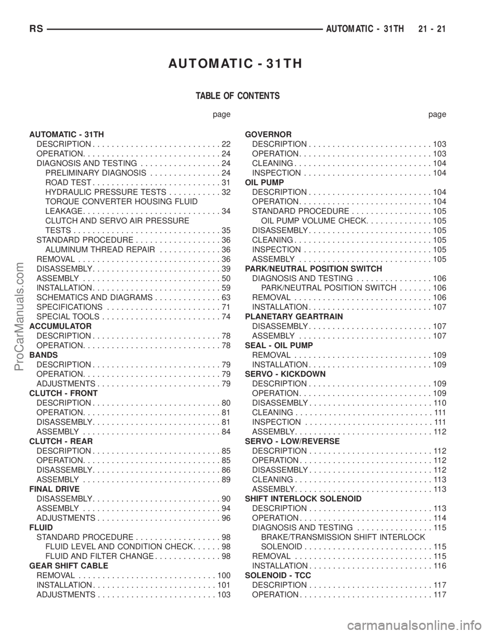
AUTOMATIC - 31TH
TABLE OF CONTENTS
page page
AUTOMATIC - 31TH
DESCRIPTION...........................22
OPERATION.............................24
DIAGNOSIS AND TESTING.................24
PRELIMINARY DIAGNOSIS...............24
ROAD TEST...........................31
HYDRAULIC PRESSURE TESTS...........32
TORQUE CONVERTER HOUSING FLUID
LEAKAGE.............................34
CLUTCH AND SERVO AIR PRESSURE
TESTS...............................35
STANDARD PROCEDURE..................36
ALUMINUM THREAD REPAIR.............36
REMOVAL..............................36
DISASSEMBLY...........................39
ASSEMBLY.............................50
INSTALLATION...........................59
SCHEMATICS AND DIAGRAMS..............63
SPECIFICATIONS........................71
SPECIAL TOOLS.........................74
ACCUMULATOR
DESCRIPTION...........................78
OPERATION.............................78
BANDS
DESCRIPTION...........................79
OPERATION.............................79
ADJUSTMENTS..........................79
CLUTCH - FRONT
DESCRIPTION...........................80
OPERATION.............................81
DISASSEMBLY...........................81
ASSEMBLY.............................84
CLUTCH - REAR
DESCRIPTION...........................85
OPERATION.............................85
DISASSEMBLY...........................86
ASSEMBLY.............................89
FINAL DRIVE
DISASSEMBLY...........................90
ASSEMBLY.............................94
ADJUSTMENTS..........................96
FLUID
STANDARD PROCEDURE..................98
FLUID LEVEL AND CONDITION CHECK......98
FLUID AND FILTER CHANGE..............98
GEAR SHIFT CABLE
REMOVAL.............................100
INSTALLATION..........................101
ADJUSTMENTS.........................103GOVERNOR
DESCRIPTION..........................103
OPERATION............................103
CLEANING.............................104
INSPECTION...........................104
OIL PUMP
DESCRIPTION..........................104
OPERATION............................104
STANDARD PROCEDURE.................105
OIL PUMP VOLUME CHECK..............105
DISASSEMBLY..........................105
CLEANING.............................105
INSPECTION...........................105
ASSEMBLY............................105
PARK/NEUTRAL POSITION SWITCH
DIAGNOSIS AND TESTING................106
PARK/NEUTRAL POSITION SWITCH.......106
REMOVAL.............................106
INSTALLATION..........................107
PLANETARY GEARTRAIN
DISASSEMBLY..........................107
ASSEMBLY............................107
SEAL - OIL PUMP
REMOVAL.............................109
INSTALLATION..........................109
SERVO - KICKDOWN
DESCRIPTION..........................109
OPERATION............................109
DISASSEMBLY..........................110
CLEANING.............................111
INSPECTION...........................111
ASSEMBLY.............................112
SERVO - LOW/REVERSE
DESCRIPTION..........................112
OPERATION............................112
DISASSEMBLY..........................112
CLEANING.............................113
ASSEMBLY.............................113
SHIFT INTERLOCK SOLENOID
DESCRIPTION..........................113
OPERATION............................114
DIAGNOSIS AND TESTING................115
BRAKE/TRANSMISSION SHIFT INTERLOCK
SOLENOID...........................115
REMOVAL.............................115
INSTALLATION..........................116
SOLENOID - TCC
DESCRIPTION..........................117
OPERATION............................117
RSAUTOMATIC - 31TH21-21
ProCarManuals.com
Page 1519 of 2321
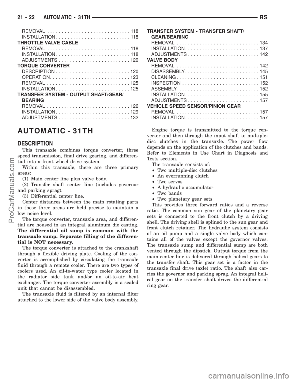
REMOVAL.............................118
INSTALLATION..........................118
THROTTLE VALVE CABLE
REMOVAL.............................118
INSTALLATION..........................118
ADJUSTMENTS.........................120
TORQUE CONVERTER
DESCRIPTION..........................120
OPERATION............................123
REMOVAL.............................125
INSTALLATION..........................125
TRANSFER SYSTEM - OUTPUT SHAFT/GEAR/
BEARING
REMOVAL.............................126
INSTALLATION..........................129
ADJUSTMENTS.........................132TRANSFER SYSTEM - TRANSFER SHAFT/
GEAR/BEARING
REMOVAL.............................134
INSTALLATION..........................137
ADJUSTMENTS.........................142
VALVE BODY
REMOVAL.............................142
DISASSEMBLY..........................145
CLEANING.............................151
INSPECTION...........................152
ASSEMBLY............................152
INSTALLATION..........................155
ADJUSTMENTS.........................157
VEHICLE SPEED SENSOR/PINION GEAR
REMOVAL.............................157
INSTALLATION..........................157
AUTOMATIC - 31TH
DESCRIPTION
This transaxle combines torque converter, three
speed transmission, final drive gearing, and differen-
tial into a front wheel drive system.
Within this transaxle, there are three primary
areas:
(1) Main center line plus valve body.
(2) Transfer shaft center line (includes governor
and parking sprag).
(3) Differential center line.
Center distances between the main rotating parts
in these three areas are held precise to maintain a
low noise level.
The torque converter, transaxle area, and differen-
tial are housed in an integral aluminum die casting.
The differential oil sump is common with the
transaxle sump. Separate filling of the differen-
tial is NOT necessary.
The torque converter is attached to the crankshaft
through a flexible driving plate. Cooling of the con-
verter is accomplished by circulating the transaxle
fluid through a remote cooler. There are two types of
coolers used. An oil-to-water type cooler located in
the radiator side tank and/or an oil-to-air heat
exchanger. The torque converter assembly is a sealed
unit that cannot be disassembled.
The transaxle fluid is filtered by an internal filter
attached to the lower side of the valve body assembly.Engine torque is transmitted to the torque con-
verter and then through the input shaft to multiple-
disc clutches in the transaxle. The power flow
depends on the application of the clutches and bands.
Refer to Elements in Use Chart in Diagnosis and
Tests section.
The transaxle consists of:
²Two multiple-disc clutches
²An overrunning clutch
²Two servos
²A hydraulic accumulator
²Two bands
²Two planetary gear sets
This provides three forward ratios and a reverse
ratio. The common sun gear of the planetary gear
sets is connected to the front clutch by a driving
shell. The driving shell is splined to the sun gear and
front clutch retainer. The hydraulic system consists
of an oil pump and a single valve body which con-
tains all of the valves except the governor valves.
The transaxle sump and differential sump are both
vented through the dipstick. Output torque from the
main center line is delivered through helical gears to
the transfer shaft. This gear set is a factor in the
transaxle final drive (axle) ratio. The shaft also car-
ries the governor and parking sprag. An integral heli-
cal gear on the transfer shaft drives the differential
ring gear.
21 - 22 AUTOMATIC - 31THRS
ProCarManuals.com
Page 1522 of 2321
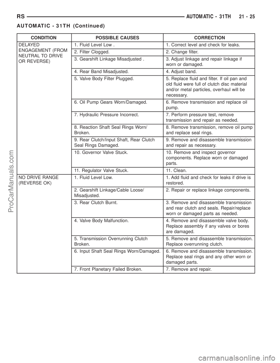
CONDITION POSSIBLE CAUSES CORRECTION
DELAYED
ENGAGEMENT (FROM
NEUTRAL TO DRIVE
OR REVERSE)1. Fluid Level Low . 1. Correct level and check for leaks.
2. Filter Clogged. 2. Change filter.
3. Gearshift Linkage Misadjusted . 3. Adjust linkage and repair linkage if
worn or damaged.
4. Rear Band Misadjusted. 4. Adjust band.
5. Valve Body Filter Plugged. 5. Replace fluid and filter. If oil pan and
old fluid were full of clutch disc material
and/or metal particles, overhaul will be
necessary.
6. Oil Pump Gears Worn/Damaged. 6. Remove transmission and replace oil
pump.
7. Hydraulic Pressure Incorrect. 7. Perform pressure test, remove
transmission and repair as needed.
8. Reaction Shaft Seal Rings Worn/
Broken.8. Remove transmission, remove oil pump
and replace seal rings.
9. Rear Clutch/Input Shaft, Rear Clutch
Seal Rings Damaged.9. Remove and disassemble transmission
and repair as necessary.
10. Governor Valve Stuck. 10. Remove and inspect governor
components. Replace worn or damaged
parts.
11. Regulator Valve Stuck. 11. Clean.
NO DRIVE RANGE
(REVERSE OK)1. Fluid Level Low. 1. Add fluid and check for leaks if drive is
restored.
2. Gearshift Linkage/Cable Loose/
Misadjusted.2. Repair or replace linkage components.
3. Rear Clutch Burnt. 3. Remove and disassemble transmission
and rear clutch and seals. Repair/replace
worn or damaged parts as needed.
4. Valve Body Malfunction. 4. Remove and disassemble valve body.
Replace assembly if any valves or bores
are damaged.
5. Transmission Overrunning Clutch
Broken.5. Remove and disassemble transmission.
Replace overrunning clutch.
6. Input Shaft Seal Rings Worn/Damaged. 6. Remove and disassemble transmission.
Replace seal rings and any other worn or
damaged parts.
7. Front Planetary Failed Broken. 7. Remove and repair.
RSAUTOMATIC - 31TH21-25
AUTOMATIC - 31TH (Continued)
ProCarManuals.com
Page 1523 of 2321
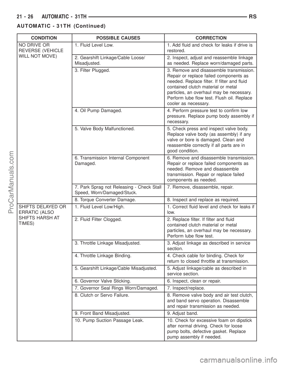
CONDITION POSSIBLE CAUSES CORRECTION
NO DRIVE OR
REVERSE (VEHICLE
WILL NOT MOVE)1. Fluid Level Low. 1. Add fluid and check for leaks if drive is
restored.
2. Gearshift Linkage/Cable Loose/
Misadjusted.2. Inspect, adjust and reassemble linkage
as needed. Replace worn/damaged parts.
3. Filter Plugged. 3. Remove and disassemble transmission.
Repair or replace failed components as
needed. Replace filter. If filter and fluid
contained clutch material or metal
particles, an overhaul may be necessary.
Perform lube flow test. Flush oil. Replace
cooler as necessary.
4. Oil Pump Damaged. 4. Perform pressure test to confirm low
pressure. Replace pump body assembly if
necessary.
5. Valve Body Malfunctioned. 5. Check press and inspect valve body.
Replace valve body (as assembly) if any
valve or bore is damaged. Clean and
reassemble correctly if all parts are in
good condition.
6. Transmission Internal Component
Damaged.6. Remove and disassemble transmission.
Repair or replace failed components as
needed. Remove and disassemble
transmission. Repair or replace failed
components as needed.
7. Park Sprag not Releasing - Check Stall
Speed, Worn/Damaged/Stuck.7. Remove, disassemble, repair.
8. Torque Converter Damage. 8. Inspect and replace as required.
SHIFTS DELAYED OR
ERRATIC (ALSO
SHIFTS HARSH AT
TIMES)1. Fluid Level Low/High. 1. Correct fluid level and check for leaks if
low.
2. Fluid Filter Clogged. 2. Replace filter. If filter and fluid
contained clutch material or metal
particles, an overhaul may be necessary.
Perform lube flow test.
3. Throttle Linkage Misadjusted. 3. Adjust linkage as described in service
section.
4. Throttle Linkage Binding. 4. Check cable for binding. Check for
return to closed throttle at transmission.
5. Gearshift Linkage/Cable Misadjusted. 5. Adjust linkage/cable as described in
service section.
6. Governor Valve Sticking. 6. Inspect, clean or repair.
7. Governor Seal Rings Worn/Damaged. 7. Inspect/replace.
8. Clutch or Servo Failure. 8. Remove valve body and air test clutch,
and band servo operation. Disassemble
and repair transmission as needed.
9. Front Band Misadjusted. 9. Adjust band.
10. Pump Suction Passage Leak. 10. Check for excessive foam on dipstick
after normal driving. Check for loose
pump bolts, defective gasket. Replace
pump assembly if needed.
21 - 26 AUTOMATIC - 31THRS
AUTOMATIC - 31TH (Continued)
ProCarManuals.com