2001 DODGE TOWN AND COUNTRY transmission oil
[x] Cancel search: transmission oilPage 1169 of 2321
NOTE: Plastigage is available in a variety of clear-
ance ranges. Use the most appropriate range for
the specifications you are checking.
(4) Install the proper crankshaft bearings to
achieve the specified bearing clearances. (Refer to 9 -
ENGINE/ENGINE BLOCK/CRANKSHAFT MAIN
BEARINGS - STANDARD PROCEDURE) (Refer to 9
- ENGINE/ENGINE BLOCK/CONNECTING ROD
BEARINGS - STANDARD PROCEDURE)
REMOVAL - ENGINE ASSEMBLY
(1) Perform fuel pressure release procedure (Refer
to 14 - FUEL SYSTEM/FUEL DELIVERY - STAN-
DARD PROCEDURE)
(2) Disconnect battery negative cable.
(3) Remove air cleaner housing and inlet tube.
(4) Disconnect the fuel line from fuel rail. (Refer to
14 - FUEL SYSTEM/FUEL DELIVERY/FUEL LINES
- STANDARD PROCEDURE)
(5) Disconnect all vacuum hoses.
(6) Drain cooling system. (Refer to 7 - COOLING -
STANDARD PROCEDURE)
(7) Remove radiator fans. (Refer to 7 - COOLING/
ENGINE/RADIATOR FAN - REMOVAL)
(8) Remove radiator upper and lower hoses.
(9) Disconnect automatic transmission cooler lines
and plug.(10) Disconnect transmission shift linkage and
electrical connectors.
(11) Disconnect throttle body linkage.
(12) Disconnect engine wiring harness.
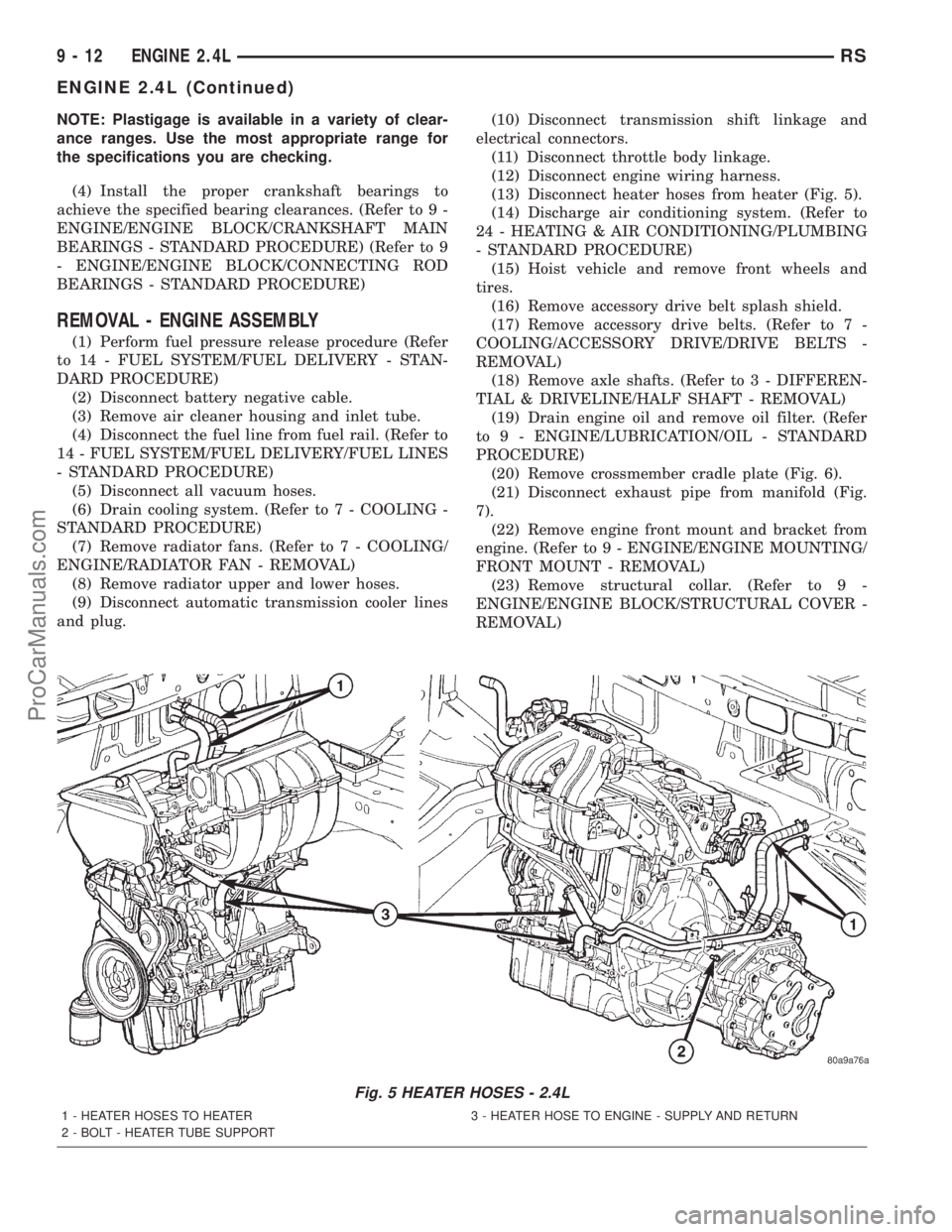
(13) Disconnect heater hoses from heater (Fig. 5).
(14) Discharge air conditioning system. (Refer to
24 - HEATING & AIR CONDITIONING/PLUMBING
- STANDARD PROCEDURE)
(15) Hoist vehicle and remove front wheels and
tires.
(16) Remove accessory drive belt splash shield.
(17) Remove accessory drive belts. (Refer to 7 -
COOLING/ACCESSORY DRIVE/DRIVE BELTS -
REMOVAL)
(18) Remove axle shafts. (Refer to 3 - DIFFEREN-
TIAL & DRIVELINE/HALF SHAFT - REMOVAL)
(19) Drain engine oil and remove oil filter. (Refer
to 9 - ENGINE/LUBRICATION/OIL - STANDARD
PROCEDURE)
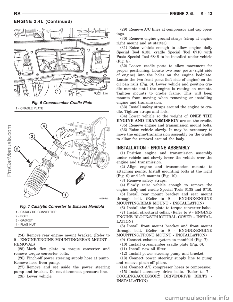
(20) Remove crossmember cradle plate (Fig. 6).
(21) Disconnect exhaust pipe from manifold (Fig.
7).
(22) Remove engine front mount and bracket from
engine. (Refer to 9 - ENGINE/ENGINE MOUNTING/
FRONT MOUNT - REMOVAL)
(23) Remove structural collar. (Refer to 9 -
ENGINE/ENGINE BLOCK/STRUCTURAL COVER -
REMOVAL)
Fig. 5 HEATER HOSES - 2.4L
1 - HEATER HOSES TO HEATER 3 - HEATER HOSE TO ENGINE - SUPPLY AND RETURN
2 - BOLT - HEATER TUBE SUPPORT
9 - 12 ENGINE 2.4LRS
ENGINE 2.4L (Continued)
ProCarManuals.com
Page 1170 of 2321
(24) Remove rear engine mount bracket. (Refer to
9 - ENGINE/ENGINE MOUNTING/REAR MOUNT -
REMOVAL)
(25) Mark flex plate to torque converter and
remove torque converter bolts.
(26) Pinch-off power steering supply hose at pump.
Remove hose from pump.
(27) Remove and set aside the power steering
pump and bracket. Do not disconnect pressure line.
(28) Lower vehicle.(29) Remove A/C lines at compressor and cap open-
ings.
(30) Remove engine ground straps (strap at engine
right mount and at starter).
(31) Raise vehicle enough to allow engine dolly
Special Tool 6135, cradle Special Tool 6710 with
Posts Special Tool 6848 to be installed under vehicle
(Fig. 8).
(32) Loosen cradle posts to allow movement for
proper positioning. Locate two rear posts (right side
of engine) into the holes on the engine bedplate.
Locate the two front posts (left side of engine) on the
oil pan rails (Fig. 8). Lower vehicle and position cra-
dle mounts until the engine is resting on mounts.
Tighten mounts to cradle frame. This will keep
mounts from moving when removing or installing
engine and transmission.
(33) Install safety straps around the engine to cra-
dle. Tighten straps and lock.
(34) Lower vehicle so the weight ofONLY THE
ENGINE AND TRANSMISSIONare on the cradle.
(35) Remove engine and transmission mount bolts.
(36) Raise vehicle slowly. It may be necessary to
move the engine/transmission assembly on the cradle
to allow for removal around the body.
INSTALLATION - ENGINE ASSEMBLY
(1) Position engine and transmission assembly
under vehicle and slowly lower the vehicle over the
engine and transmission.
(2) Align engine and transmission mounts to
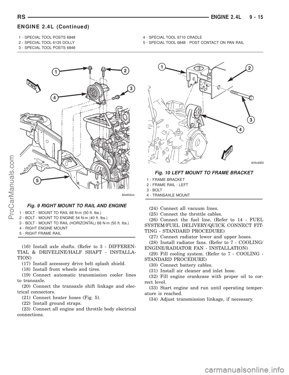
attaching points. Install mounting bolts at the right
(Fig. 9) and left mounts (Fig. 10).
(3) Remove safety straps.
(4) Slowly raise vehicle enough to remove the
engine dolly and cradle Special Tools 6135 and 6710.
(5) Install rear mount bracket and rear mount
through bolt. (Refer to 9 - ENGINE/ENGINE
MOUNTING/REAR MOUNT - INSTALLATION)
(6) Install the flex plate to torque converter bolts.
(7) Install structural collar. (Refer to 9 - ENGINE/
ENGINE BLOCK/STRUCTURAL COVER - INSTAL-
LATION)
(8) Install front mount bracket and front mount
through bolt. (Refer to 9 - ENGINE/ENGINE
MOUNTING/FRONT MOUNT - INSTALLATION)
(9) Connect exhaust system to manifold (Fig. 7).
(10) Install crossmember cradle plate (Fig. 6).
(11) Install new oil filter.
(12) Install power steering pump and bracket.
(13) Connect power steering supply line to pump
and remove pinch-off pliers.
(14) Connect A/C compressor hoses to compressor.
(15) Install accessory drive belts. (Refer to 7 -
COOLING/ACCESSORY DRIVE/DRIVE BELTS -
INSTALLATION)
Fig. 6 Crossmember Cradle Plate
1 - CRADLE PLATE
Fig. 7 Catalytic Converter to Exhaust Manifold
1 - CATALYTIC CONVERTER
2 - BOLT
3 - GASKET
4 - FLAG NUT
RSENGINE 2.4L9-13
ENGINE 2.4L (Continued)
ProCarManuals.com
Page 1172 of 2321
(16) Install axle shafts. (Refer to 3 - DIFFEREN-
TIAL & DRIVELINE/HALF SHAFT - INSTALLA-
TION)
(17) Install accessory drive belt splash shield.
(18) Install front wheels and tires.
(19) Connect automatic transmission cooler lines
to transaxle.
(20) Connect the transaxle shift linkage and elec-
trical connectors.
(21) Connect heater hoses (Fig. 5).
(22) Install ground straps.
(23) Connect all engine and throttle body electrical
connections.(24) Connect all vacuum lines.
(25) Connect the throttle cables.
(26) Connect the fuel line. (Refer to 14 - FUEL
SYSTEM/FUEL DELIVERY/QUICK CONNECT FIT-
TING - STANDARD PROCEDURE)
(27) Connect radiator lower and upper hoses.
(28) Install radiator fans. (Refer to 7 - COOLING/
ENGINE/RADIATOR FAN - INSTALLATION)
(29) Fill cooling system. (Refer to 7 - COOLING -
STANDARD PROCEDURE)
(30) Connect battery cables.
(31) Install air cleaner and inlet hose.
(32) Fill engine crankcase with proper oil to cor-
rect level.
(33) Start engine and run until operating temper-
ature is reached.
(34) Adjust transmission linkage, if necessary.
1 - SPECIAL TOOL POSTS 6848 4 - SPECIAL TOOL 6710 CRADLE
2 - SPECIAL TOOL 6135 DOLLY 5 - SPECIAL TOOL 6848 - POST CONTACT ON PAN RAIL
3 - SPECIAL TOOL POSTS 6848
Fig. 9 RIGHT MOUNT TO RAIL AND ENGINE
1 - BOLT - MOUNT TO RAIL 68 N´m (50 ft. lbs.)
2 - BOLT - MOUNT TO ENGINE 54 N´m (40 ft. lbs.)
3 - BOLT - MOUNT TO RAIL (HORIZONTAL) 68 N´m (50 ft. lbs.)
4 - RIGHT ENGINE MOUNT
5 - RIGHT FRAME RAIL
Fig. 10 LEFT MOUNT TO FRAME BRACKET
1 - FRAME BRACKET
2 - FRAME RAIL - LEFT
3 - BOLT
4 - TRANSAXLE MOUNT
RSENGINE 2.4L9-15
ENGINE 2.4L (Continued)
ProCarManuals.com
Page 1191 of 2321
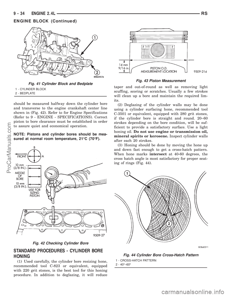
should be measured halfway down the cylinder bore
and transverse to the engine crankshaft center line
shown in (Fig. 42). Refer to for Engine Specifications
(Refer to 9 - ENGINE - SPECIFICATIONS). Correct
piston to bore clearance must be established in order
to assure quiet and economical operation.
NOTE: Pistons and cylinder bores should be mea-
sured at normal room temperature, 21ÉC (70ÉF).
STANDARD PROCEDURES - CYLINDER BORE
HONING
(1) Used carefully, the cylinder bore resizing hone,
recommended tool C-823 or equivalent, equipped
with 220 grit stones, is the best tool for this honing
procedure. In addition to deglazing, it will reducetaper and out-of-round as well as removing light
scuffing, scoring or scratches. Usually a few strokes
will clean up a bore and maintain the required lim-
its.
(2) Deglazing of the cylinder walls may be done
using a cylinder surfacing hone, recommended tool
C-3501 or equivalent, equipped with 280 grit stones,
if the cylinder bore is straight and round. 20±60
strokes depending on the bore condition, will be suf-
ficient to provide a satisfactory surface. Use a light
honing oil.Do not use engine or transmission oil,
mineral spirits or kerosene.Inspect cylinder walls
after each 20 strokes.
(3) Honing should be done by moving the hone up
and down fast enough to get a cross-hatch pattern.
When hone marksintersectat 40-60 degrees, the
cross hatch angle is most satisfactory for proper seat-
ing of rings (Fig. 44).
Fig. 41 Cylinder Block and Bedplate
1 - CYLINDER BLOCK
2 - BEDPLATE
Fig. 42 Checking Cylinder Bore
Fig. 43 Piston Measurement
Fig. 44 Cylinder Bore Cross-Hatch Pattern
1 - CROSS-HATCH PATTERN
2 - 40ɱ60É
9 - 34 ENGINE 2.4LRS
ENGINE BLOCK (Continued)
ProCarManuals.com
Page 1235 of 2321
²Gradually apply air pressure from 1 psi to 2.5
psi maximum while applying soapy water at the sus-
pected source. Adjust the regulator to the suitable
test pressure that provides the best bubbles which
will pinpoint the leak source. If the oil leak is
detected and identified, repair per service manual
procedures.
²If the leakage occurs at the crankshaft rear oil
seal area, refer to the section, Inspection for Rear
Seal Area Leak.
(6) If no leaks are detected, turn off the air supply.
Remove the air hose, all plugs, and caps. Install the
PCV valve and fresh air hose (make-up air). Proceed
to next step.
(7) Clean the oil off the suspect oil leak area using
a suitable solvent. Drive the vehicle at various
speeds approximately 24 km (15 miles). Inspect the
engine for signs of an oil leak by using a black light.
NOTE: If oil leakage is observed at the dipstick tube
to block location; remove the tube, clean and reseal
using MoparTStud & Bearing Mount (press fit tube
applications only), and for O-ring style tubes,
remove tube and replace the O-ring seal.
INSPECTION FOR REAR SEAL AREA LEAKS
Since it is sometimes difficult to determine the
source of an oil leak in the rear seal area of the
engine, a more involved inspection is necessary. The
following steps should be followed to help pinpoint
the source of the leak.
If the leakage occurs at the crankshaft rear oil seal
area:
(1) Disconnect the battery.
(2) Raise the vehicle.
(3) Remove torque converter or clutch housing
cover and inspect rear of block for evidence of oil.
Use a black light to check for the oil leak. If a leak is
present in this area, remove transmission for further
inspection.
(a) Circular spray pattern generally indicates
seal leakage or crankshaft damage.
(b) Where leakage tends to run straight down,
possible causes are a porous block, oil gallery cup
plug, bedplate to cylinder block mating surfaces
and seal bore. See proper repair procedures for
these items.
(4) If no leaks are detected, pressurize the crank-
case as previously described.
CAUTION: Do not exceed 20.6 kPa (3 psi).
(5) If the leak is not detected, very slowly turn the
crankshaft and watch for leakage. If a leak is
detected between the crankshaft and seal while
slowly turning the crankshaft, it is possible thecrankshaft seal surface is damaged. The seal area on
the crankshaft could have minor nicks or scratches
that can be polished out with emery cloth.
CAUTION: Use extreme caution when crankshaft
polishing is necessary to remove minor nicks and
scratches. The crankshaft seal flange is especially
machined to complement the function of the rear oil
seal.
(6) For bubbles that remain steady with shaft
rotation, no further inspection can be done until dis-
assembled.
(7) After the oil leak root cause and appropriate
corrective action have been identified, replace compo-
nent(s) as necessary.
DIAGNOSIS AND TESTING - CYLINDER
COMPRESSION PRESSURE
The results of a cylinder compression pressure test
can be utilized to diagnose several engine malfunc-
tions.
Ensure the battery is completely charged and the
engine starter motor is in good operating condition.
Otherwise the indicated compression pressures may
not be valid for diagnosis purposes.
(1) Check engine oil level and add oil if necessary.
(2) Drive the vehicle until engine reaches normal
operating temperature. Select a route free from traf-
fic and other forms of congestion, observe all traffic
laws, and accelerate through the gears several times
briskly.
(3) Remove all spark plugs from engine. As spark
plugs are being removed, check electrodes for abnor-
mal firing indicators fouled, hot, oily, etc. Record cyl-
inder number of spark plug for future reference.
(4) Disconnect the ignition coil electrical connector.
(5) Be sure throttle blade is fully open during the
compression check.
(6) Insert compression gage adaptor Special Tool
8116 or the equivalent, into the #1 spark plug hole in
cylinder head. Connect the 0±500 psi (Blue) pressure
transducer with cable adaptors to the DRBIIIt.
(7) Crank engine until maximum pressure is
reached on gage. Record this pressure as #1 cylinder
pressure.
(8) Repeat the previous step for all remaining cyl-
inders.
(9) Compression should not be less than 689 kPa
(100 psi) and not vary more than 25 percent from cyl-
inder to cylinder.
(10) If one or more cylinders have abnormally low
compression pressures, repeat the compression test.
(11) If the same cylinder or cylinders repeat an
abnormally low reading on the second compression
test, it could indicate the existence of a problem in
9 - 78 ENGINE 3.3/3.8LRS
ENGINE 3.3/3.8L (Continued)
ProCarManuals.com
Page 1237 of 2321
when applying form-in-place gaskets to assure
obtaining the desired results.Do not use form-in-
place gasket material unless specified.Bead size,
continuity, and location are of great importance. Too
thin a bead can result in leakage while too much can
result in spill-over which can break off and obstruct
fluid feed lines. A continuous bead of the proper
width is essential to obtain a leak-free gasket.
There are numerous types of form-in-place gasket
materials that are used in the engine area. Mopart
Engine RTV GEN II, MopartATF-RTV, and Mopart
Gasket Maker gasket materials, each have different
properties and can not be used in place of the other.
MOPARtENGINE RTV GEN IIis used to seal
components exposed to engine oil. This material is a
specially designed black silicone rubber RTV that
retains adhesion and sealing properties when
exposed to engine oil. Moisture in the air causes the
material to cure. This material is available in three
ounce tubes and has a shelf life of one year. After one
year this material will not properly cure. Always
inspect the package for the expiration date before
use.
MOPARtATF RTVis a specifically designed
black silicone rubber RTV that retains adhesion and
sealing properties to seal components exposed to
automatic transmission fluid, engine coolants, and
moisture. This material is available in three ounce
tubes and has a shelf life of one year. After one year
this material will not properly cure. Always inspect
the package for the expiration date before use.
MOPARtGASKET MAKERis an anaerobic type
gasket material. The material cures in the absence of
air when squeezed between two metallic surfaces. It
will not cure if left in the uncovered tube. The
anaerobic material is for use between two machined
surfaces. Do not use on flexible metal flanges.
MOPARtBED PLATE SEALANTis a unique
(green-in-color) anaerobic type gasket material that
is specially made to seal the area between the bed-
plate and cylinder block without disturbing the bear-
ing clearance or alignment of these components. The
material cures slowly in the absence of air when
torqued between two metallic surfaces, and will rap-
idly cure when heat is applied.
MOPARtGASKET SEALANTis a slow drying,
permanently soft sealer. This material is recom-
mended for sealing threaded fittings and gaskets
against leakage of oil and coolant. Can be used on
threaded and machined parts under all tempera-
tures. This material is used on engines with multi-
layer steel (MLS) cylinder head gaskets. This
material also will prevent corrosion. MopartGasket
Sealant is available in a 13 oz. aerosol can or 4oz./16
oz. can w/applicator.SEALER APPLICATION
MopartGasket Maker material should be applied
sparingly 1 mm (0.040 in.) diameter or less of sealant
to one gasket surface. Be certain the material sur-
rounds each mounting hole. Excess material can eas-
ily be wiped off. Components should be torqued in
place within 15 minutes. The use of a locating dowel
is recommended during assembly to prevent smear-
ing material off the location.
MopartEngine RTV GEN II or ATF RTV gasket
material should be applied in a continuous bead
approximately 3 mm (0.120 in.) in diameter. All
mounting holes must be circled. For corner sealing, a
3.17 or 6.35 mm (1/8 or 1/4 in.) drop is placed in the
center of the gasket contact area. Uncured sealant
may be removed with a shop towel. Components
should be torqued in place while the sealant is still
wet to the touch (within 10 minutes). The usage of a
locating dowel is recommended during assembly to
prevent smearing material off the location.
MopartGasket Sealant in an aerosol can should be
applied using a thin, even coat sprayed completely
over both surfaces to be joined, and both sides of a
gasket. Then proceed with assembly. Material in a
can w/applicator can be brushed on evenly over the
sealing surfaces. Material in an aerosol can should be
used on engines with multi-layer steel gaskets.
STANDARD PROCEDURES - ENGINE GASKET
SURFACE PREPARATION
To ensure engine gasket sealing, proper surface
preparation must be performed, especially with the
use of aluminum engine components and multi-layer
steel cylinder head gaskets.
Neveruse the following to clean gasket surfaces:
²Metal scraper
²Abrasive pad or paper to clean cylinder block
and head
²High speed power tool with an abrasive pad or a
wire brush (Fig. 4)
NOTE: Multi-Layer Steel (MLS) head gaskets require
a scratch free sealing surface.
Only use the following for cleaning gasket surfaces:
²Solvent or a commercially available gasket
remover
²Plastic or wood scraper (Fig. 4)
²Drill motor with 3M RolocyBristle Disc (white
or yellow) (Fig. 4)
9 - 80 ENGINE 3.3/3.8LRS
ENGINE 3.3/3.8L (Continued)
ProCarManuals.com
Page 1243 of 2321
(43) Connect the vacuum hoses to the throttle
body.
(44) Connect the EGR transducer electrical connec-
tor.
(45) Connect the TPS, IAC, and MAP sensor elec-
trical connectors.
(46) Connect throttle cables to throttle body.
(47) Install the radiator fans. (Refer to 7 - COOL-
ING/ENGINE/RADIATOR FAN - INSTALLATION)
(48) Connect the radiator upper hose.
(49) Connect the heater hoses. Remove pinch-off
pliers from the rear heater hoses, if equipped.
(50) Install the radiator upper support crossmem-
ber. (Refer to 23 - BODY/EXTERIOR/GRILLE OPEN-
ING REINFORCEMENT - INSTALLATION)
(51) Install the wiper module. (Refer to 8 - ELEC-
TRICAL/WIPERS/WASHERS/WIPER MODULE -
INSTALLATION)
(52) Connect the fuel line to fuel rail. (Refer to 14
- FUEL SYSTEM/FUEL DELIVERY/FUEL LINES -
STANDARD PROCEDURE)
(53) Install the air cleaner and hoses.
(54) Install new oil filter. Fill engine crankcase
with proper oil to correct level.
(55) Connect negative cable to battery.
(56) Fill the cooling system. (Refer to 7 - COOL-
ING - STANDARD PROCEDURE)
(57) Start engine and run until operating temper-
ature is reached.
(58) Adjust transmission linkage, if necessary.
SPECIFICATIONS
3.3/3.8L ENGINE
DESCRIPTION SPECIFICATION
General Specification
Type 60É V-6 Engine
Number of Cylinders 6
Displacement
Ð3.3L 3.3 Liters
(201 cu. in.)
Ð3.8L 3.8 Liters
(231 cu. in.)
Bore
Ð3.3L 93.0 mm
(3.66 in.)
Ð3.8L 96.0 mm
(3.779 in.)
DESCRIPTION SPECIFICATION
Stroke
Ð3.3L 81.0 mm
(3.188 in.)
Ð3.8L 87.0 mm
(3.425 in.)
Compression Ratio
Ð3.3L 9.35:1
Ð3.8L 9.6:1
Firing Order 1-2-3-4-5-6
Cylinder Number (Front
to Rear)
ÐFront Bank 2,4,6
ÐRear Bank 1,3,5
Compression PressureÐ
Minimum689.5 kPa
(100 psi)
Max. Variation Between
Cylinders25%
Cylinder Block
Cylinder Bore Diameter
(Standard)
Ð3.3L 92.993±93.007 mm
(3.661±3.6617 in.)
Ð3.8L 95.993±96.007 mm
(3.7792±3.780 in.)
Out-of-Round (Service
Limits)0.076 mm
(0.003 in.)
Taper (Service Limits) 0.051 mm
(0.002 in.)
Lifter Bore Diameter 22.980±23.010 mm
(0.905±0.906 in.)
Deck Surface Flatness
(Max.)0.1 mm
(0.004 in.)
Pistons
Piston Diameter
Ð3.3L ÐMeasured 39.8
mm (1.567 in.) from
piston top92.968±92.998 mm
(3.660±3.661 in.)
Ð3.8L ÐMeasured 33.01
mm (1.30 in.) from piston
top95.968±95.998 mm
(3.778±3.779 in.)
Clearance in Bore @
Size Location (New)-0.005±0.039 mm
(-0.0002±0.0015 in.)
9 - 86 ENGINE 3.3/3.8LRS
ENGINE 3.3/3.8L (Continued)
ProCarManuals.com
Page 1263 of 2321
(3) Slowly tighten rocker shaft bolts evenly until
shaft is seated. Tighten bolts to 23 N´m (200 in. lbs.)
(Fig. 41).
(4) Install the cylinder head cover(s). (Refer to 9 -
ENGINE/CYLINDER HEAD/CYLINDER HEAD
COVER(S) - INSTALLATION)
VALVE STEM SEALS
DESCRIPTION
The valve stem seals are made of Viton rubber. The
seals are positioned over the valve stem and seated
on the valve guide (Fig. 42).
REMOVAL
(1) Remove the valve springs. (Refer to 9 -
ENGINE/CYLINDER HEAD/VALVE SPRINGS -
REMOVAL)
(2) Remove the valve stem seal (Fig. 42).
INSTALLATION
(1) Install the valve stem seal squarely over the
valve guide, using the valve stem as a guide (Fig.
42). Do not force the seal against top of the valve
guide.
(2) Install the valve spring. (Refer to 9 - ENGINE/
CYLINDER HEAD/VALVE SPRINGS - INSTALLA-
TION)
ENGINE BLOCK
DESCRIPTION
The cylinder block is made of cast iron and is a
deep skirt design.
STANDARD PROCEDURES - CYLINDER BORE
HONING
(1)Used carefully, the cylinder bore resizing hone,
recommended tool C-823 or equivalent, equipped with
220 grit stones, is the best tool for this honing proce-
dure. In addition to deglazing, it will reduce taper and
out-of-round as well as removing light scuffing, scor-
ing or scratches. Usually a few strokes will clean up a
bore and maintain the required limits.
(2) Deglazing of the cylinder walls may be done
using a cylinder surfacing hone, recommended tool
C-3501 or equivalent, equipped with 280 grit stones,
if the cylinder bore is straight and round. 20±60
strokes depending on the bore condition, will be suf-
ficient to provide a satisfactory surface. Use a light
honing oil.Do not use engine or transmission oil,
mineral spirits or kerosene.Inspect cylinder walls
after each 20 strokes.
(3) Honing should be done by moving the hone up
and down fast enough to get a cross-hatch pattern.
When hone marksintersectat 40-60 degrees, the
cross hatch angle is most satisfactory for proper seat-
ing of rings (Fig. 43).
(4) A controlled hone motor speed between
200±300 RPM is necessary to obtain the proper cross-
hatch angle. The number of up and down strokes per
minute can be regulated to get the desired 40±60
degree angle. Faster up and down strokes increase
the cross-hatch angle.
(5) After honing, it is necessary that the block be
cleaned again to remove all traces of abrasive.
CAUTION: Ensure all abrasives are removed from
engine parts after honing. It is recommended that a
solution of soap and hot water be used with a
brush and the parts then thoroughly dried. The bore
can be considered clean when it can be wiped
clean with a white cloth and cloth remains clean.
Oil the bores after cleaning to prevent rusting.
Fig. 41 ROCKER ARMS AND SHAFT
1 - ROCKER ARMS AND SHAFT ASSEMBLY
2 - ROCKER SHAFT BOLTS
Fig. 42 Valve Stem Seal
9 - 106 ENGINE 3.3/3.8LRS
ROCKER ARMS (Continued)
ProCarManuals.com