2001 DODGE TOWN AND COUNTRY brake light
[x] Cancel search: brake lightPage 1903 of 2321
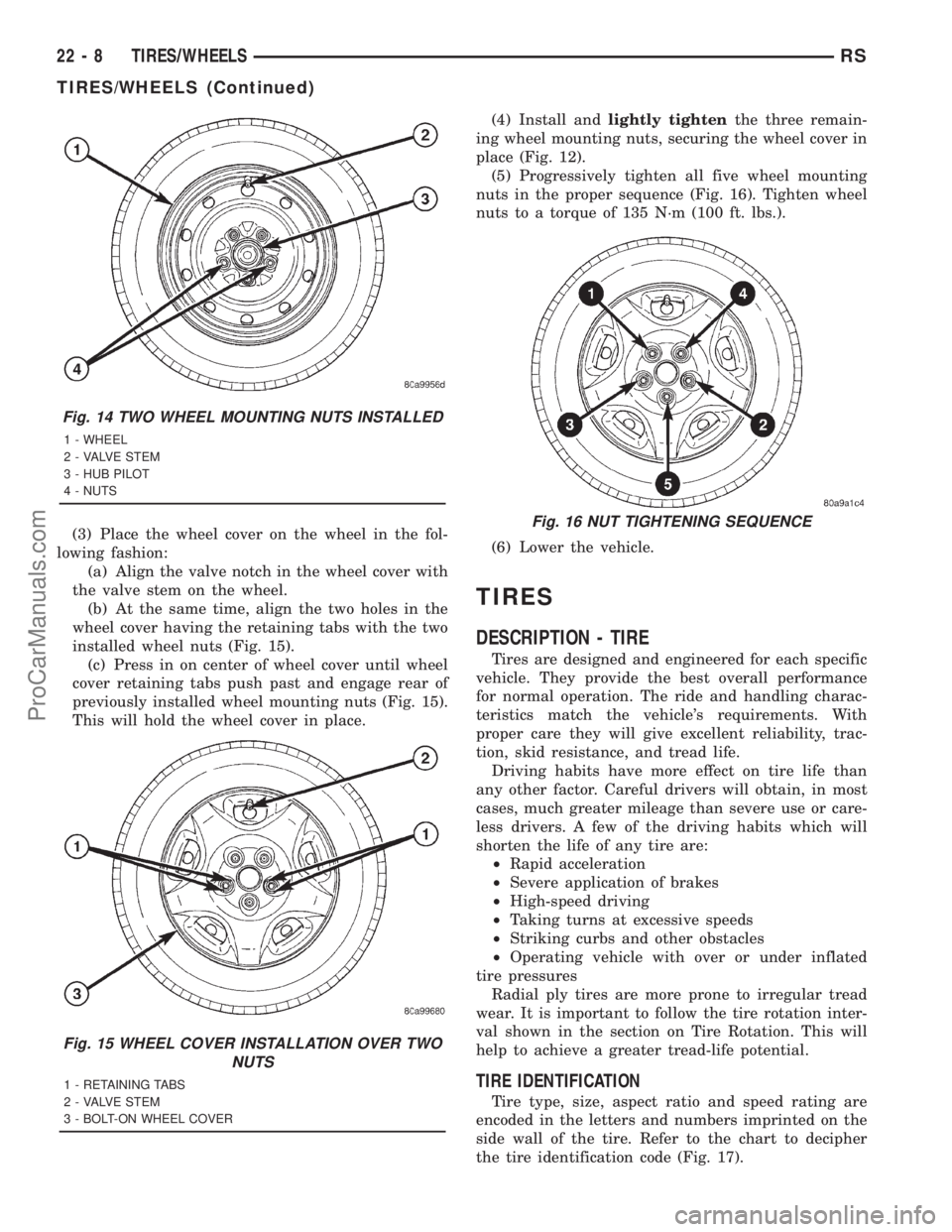
(3) Place the wheel cover on the wheel in the fol-
lowing fashion:
(a) Align the valve notch in the wheel cover with
the valve stem on the wheel.
(b) At the same time, align the two holes in the
wheel cover having the retaining tabs with the two
installed wheel nuts (Fig. 15).
(c) Press in on center of wheel cover until wheel
cover retaining tabs push past and engage rear of
previously installed wheel mounting nuts (Fig. 15).
This will hold the wheel cover in place.(4) Install andlightly tightenthe three remain-
ing wheel mounting nuts, securing the wheel cover in
place (Fig. 12).
(5) Progressively tighten all five wheel mounting
nuts in the proper sequence (Fig. 16). Tighten wheel
nuts to a torque of 135 N´m (100 ft. lbs.).
(6) Lower the vehicle.
TIRES
DESCRIPTION - TIRE
Tires are designed and engineered for each specific
vehicle. They provide the best overall performance
for normal operation. The ride and handling charac-
teristics match the vehicle's requirements. With
proper care they will give excellent reliability, trac-
tion, skid resistance, and tread life.
Driving habits have more effect on tire life than
any other factor. Careful drivers will obtain, in most
cases, much greater mileage than severe use or care-
less drivers. A few of the driving habits which will
shorten the life of any tire are:
²Rapid acceleration
²Severe application of brakes
²High-speed driving
²Taking turns at excessive speeds
²Striking curbs and other obstacles
²Operating vehicle with over or under inflated
tire pressures
Radial ply tires are more prone to irregular tread
wear. It is important to follow the tire rotation inter-
val shown in the section on Tire Rotation. This will
help to achieve a greater tread-life potential.
TIRE IDENTIFICATION
Tire type, size, aspect ratio and speed rating are
encoded in the letters and numbers imprinted on the
side wall of the tire. Refer to the chart to decipher
the tire identification code (Fig. 17).
Fig. 14 TWO WHEEL MOUNTING NUTS INSTALLED
1 - WHEEL
2 - VALVE STEM
3 - HUB PILOT
4 - NUTS
Fig. 15 WHEEL COVER INSTALLATION OVER TWO
NUTS
1 - RETAINING TABS
2 - VALVE STEM
3 - BOLT-ON WHEEL COVER
Fig. 16 NUT TIGHTENING SEQUENCE
22 - 8 TIRES/WHEELSRS
TIRES/WHEELS (Continued)
ProCarManuals.com
Page 1910 of 2321
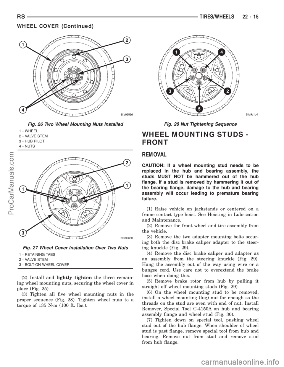
(2) Install andlightly tightenthe three remain-
ing wheel mounting nuts, securing the wheel cover in
place (Fig. 25).
(3) Tighten all five wheel mounting nuts in the
proper sequence (Fig. 28). Tighten wheel nuts to a
torque of 135 N´m (100 ft. lbs.).
WHEEL MOUNTING STUDS -
FRONT
REMOVAL
CAUTION: If a wheel mounting stud needs to be
replaced in the hub and bearing assembly, the
studs MUST NOT be hammered out of the hub
flange. If a stud is removed by hammering it out of
the bearing flange, damage to the hub and bearing
assembly will occur leading to premature bearing
failure.
(1) Raise vehicle on jackstands or centered on a
frame contact type hoist. See Hoisting in Lubrication
and Maintenance.
(2) Remove the front wheel and tire assembly from
the vehicle.
(3) Remove the two adapter mounting bolts secur-
ing both the disc brake caliper adapter to the steer-
ing knuckle (Fig. 29).
(4) Remove the disc brake caliper and adapter as
an assembly from the steering knuckle (Fig. 29).
Hang the assembly out of the way using wire or a
bungee cord. Use care not to overextend the brake
hose when doing this.
(5) Remove brake rotor from hub by pulling it
straight off wheel mounting studs (Fig. 29).
(6) On the wheel mounting stud to be removed,
install a wheel mounting (lug) nut far enough so the
threads on the stud are even with end of nut. Install
Remover, Special Tool C-4150A on hub and bearing
assembly flange and wheel stud (Fig. 30).
(7) Tighten down on special tool, pushing wheel
stud out of the hub flange. When shoulder of wheel
stud is past flange, remove special tool from hub and
bearing. Remove nut from stud and remove stud
from hub flange.
Fig. 26 Two Wheel Mounting Nuts Installed
1 - WHEEL
2 - VALVE STEM
3 - HUB PILOT
4 - NUTS
Fig. 27 Wheel Cover Installation Over Two Nuts
1 - RETAINING TABS
2 - VALVE STEM
3 - BOLT-ON WHEEL COVER
Fig. 28 Nut Tightening Sequence
RSTIRES/WHEELS22-15
WHEEL COVER (Continued)
ProCarManuals.com
Page 2241 of 2321
(3) Remove the silencer boot fasteners located
around the base of the lower steering shaft from the
dash panel so that it may be pushed aside.
(4) Remove the brake lamp switch from its mount-
ing bracket. (Refer to 8 - ELECTRICAL/LAMPS/
LIGHTING - EXTERIOR/BRAKE LAMP SWITCH -
REMOVAL).
(5) Disconnect the power brake booster input rod
(push rod) from the pin on the brake pedal arm.
(Refer to 5 - BRAKES - ABS/HYDRAULIC/ME-
CHANICAL/POWER BRAKE BOOSTER - REMOV-
AL).
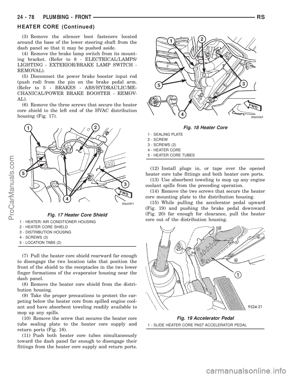
(6) Remove the three screws that secure the heater
core shield to the left end of the HVAC distribution
housing (Fig. 17).
(7) Pull the heater core shield rearward far enough
to disengage the two location tabs that position the
front of the shield to the receptacles in the two lower
finger formations of the evaporator housing near the
dash panel.
(8) Remove the heater core shield from the distri-
bution housing.
(9) Take the proper precautions to protect the car-
peting below the heater core from spilled engine cool-
ant and have absorbent toweling readily available to
mop up any spills.
(10) Remove the screw that secures the heater core
tube sealing plate to the heater core supply and
return ports (Fig. 18).
(11) Push both heater core tubes simultaneously
toward the dash panel far enough to disengage their
fittings from the heater core supply and return ports.(12) Install plugs in, or tape over the opened
heater core tube fittings and both heater core ports.
(13) Use absorbent toweling to mop up any engine
coolant spills from the preceding operation.
(14) Remove the two screws that secure the heater
core mounting plate to the distribution housing.
(15) While pulling the accelerator pedal upward
(Fig. 19) and pushing the brake pedal downward
(Fig. 20) far enough for clearance, pull the heater
core out of the distribution housing.
Fig. 17 Heater Core Shield
1 - HEATER/ AIR CONDITIONER HOUSING
2 - HEATER CORE SHIELD
3 - DISTRIBUTION HOUSING
4 - SCREWS (3)
5 - LOCATION TABS (2)
Fig. 18 Heater Core
1 - SEALING PLATE
2 - SCREW
3 - SCREWS (2)
4 - HEATER CORE
5 - HEATER CORE TUBES
Fig. 19 Accelerator Pedal
1 - SLIDE HEATER CORE PAST ACCELERATOR PEDAL
24 - 78 PLUMBING - FRONTRS
HEATER CORE (Continued)
ProCarManuals.com
Page 2243 of 2321
INSTALLATION - HEATER CORE
WARNING: REFER TO THE APPLICABLE WARN-
INGS AND CAUTIONS FOR THIS SYSTEM BEFORE
PERFORMING THE FOLLOWING OPERATION.
(Refer to 24 - HEATING & AIR CONDITIONING/
PLUMBING FRONT - WARNING - HEATER PLUMB-
ING).
WARNING: ON VEHICLES EQUIPPED WITH AIR-
BAGS, DISABLE THE AIRBAG SYSTEM BEFORE
ATTEMPTING ANY STEERING WHEEL, STEERING
COLUMN, OR INSTRUMENT PANEL COMPONENT
DIAGNOSIS OR SERVICE. DISCONNECT AND ISO-
LATE THE BATTERY NEGATIVE (GROUND) CABLE,
THEN WAIT TWO MINUTES FOR THE AIRBAG SYS-
TEM CAPACITOR TO DISCHARGE BEFORE PER-
FORMING FURTHER DIAGNOSIS OR SERVICE. THIS
IS THE ONLY SURE WAY TO DISABLE THE AIRBAG
SYSTEM. FAILURE TO TAKE THE PROPER PRE-
CAUTIONS COULD RESULT IN ACCIDENTAL AIR-
BAG DEPLOYMENT AND POSSIBLE PERSONAL
INJURY.
(1) While pushing the brake pedal downward (Fig.
20) and pulling the accelerator pedal upward (Fig.
19) far enough for clearance, slide the heater core
into the distribution housing.
(2) Install and tighten the two screws that secure
the heater core mounting plate to the distribution
housing (Fig. 18). Tighten the screws to 2 N´m (17 in.
lbs.).
(3) Remove the plugs or tape from the heater core
tube fittings and both heater core ports.
(4) Position both heater core tubes and the sealing
plate simultaneously to the heater core supply and
return ports.
(5) The heater core tubes each have a slot that
must be indexed to a location tab within each of the
heater core ports. Adjust the position of the tubes as
required so that the sealing plate fits flush against
the heater core supply and return ports, which indi-
cates that the tubes are properly indexed.
(6) Install and tighten the screw that secures the
heater core tube sealing plate to the heater core sup-
ply and return ports. Tighten the screw to 3 N´m (27
in. lbs.).
(7) Position the heater core shield onto the distri-
bution housing. Be certain that the two location tabs
on the front of the shield are engaged in the recepta-
cles in the two lower finger formations of the evapo-
rator housing near the dash panel (Fig. 17).
(8) Install and tighten the three screws that secure
the heater core shield to the left end of the HVAC
distribution housing. Tighten the screws to 2 N´m (17
in. lbs.).(9) Reconnect the power brake booster input rod
(push rod) to the pin on the brake pedal arm. (Refer
to 5 - BRAKES - ABS/HYDRAULIC/MECHANICAL/
POWER BRAKE BOOSTER - INSTALLATION).
(10) Reinstall the brake lamp switch into its
mounting bracket. (Refer to 8 - ELECTRICAL/
LAMPS/LIGHTING - EXTERIOR/BRAKE LAMP
SWITCH - INSTALLATION).
(11) Reinstall the silencer boot around the base of
the lower steering shaft on the dash panel.
(12) Reconnect the battery negative cable.
(13) Refill the engine cooling system. (Refer to 7 -
COOLING - STANDARD PROCEDURE - COOLING
SYSTEM REFILL).
(14) Operate sustem for two thermostat cycles to
assure elimination of air in the system.
HEATER HOSE
REMOVAL
There are several heater core plumbing configura-
tions used on this model, depending upon the engine
size and other optional equipment. One plumbing
configuration is used for all 2.4L engines (Fig. 21),
while the 3.3L and 3.8L engines have unique heater
return plumbing on the engine for models with or
without an optional engine oil cooler (Fig. 24) or (Fig.
25). There are also unique plumbing configurations
at the heater core for models with or without the
optional rear heater and air conditioner (Fig. 22) or
(Fig. 23). All models use a combination of formed
steel tubing and rubber hoses. In most cases, the
rubber hose is secured to the steel tubing with a
spring tension clamp.
WARNING: REFER TO THE APPLICABLE WARN-
INGS AND CAUTIONS FOR THIS SYSTEM BEFORE
PERFORMING THE FOLLOWING OPERATION.
(Refer to 24 - HEATING & AIR CONDITIONING/
PLUMBING FRONT - WARNING - HEATER PLUMB-
ING).
(1) Drain the engine cooling system. (Refer to 7 -
COOLING - STANDARD PROCEDURE - COOLING
SYSTEM DRAIN).
(2) Using spring tension clamp pliers, compress
and slide the clamps that secure each end of the
heater hose to the tube or nipple toward the center of
the hose to be removed. Release the clamp when it is
off of the tube or nipple.
24 - 80 PLUMBING - FRONTRS
HEATER CORE (Continued)
ProCarManuals.com
Page 2300 of 2321
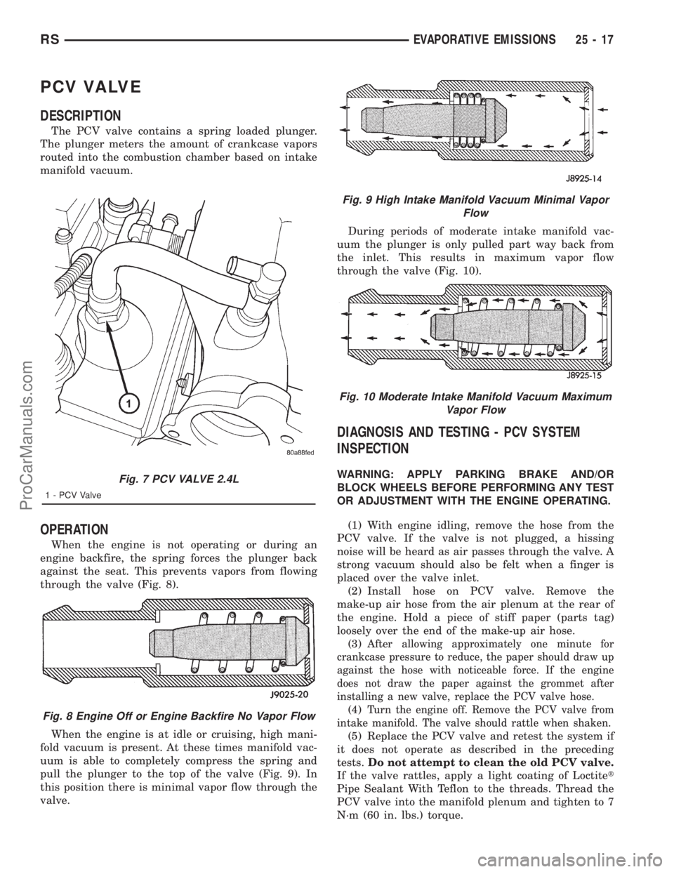
PCV VALVE
DESCRIPTION
The PCV valve contains a spring loaded plunger.
The plunger meters the amount of crankcase vapors
routed into the combustion chamber based on intake
manifold vacuum.
OPERATION
When the engine is not operating or during an
engine backfire, the spring forces the plunger back
against the seat. This prevents vapors from flowing
through the valve (Fig. 8).
When the engine is at idle or cruising, high mani-
fold vacuum is present. At these times manifold vac-
uum is able to completely compress the spring and
pull the plunger to the top of the valve (Fig. 9). In
this position there is minimal vapor flow through the
valve.During periods of moderate intake manifold vac-
uum the plunger is only pulled part way back from
the inlet. This results in maximum vapor flow
through the valve (Fig. 10).
DIAGNOSIS AND TESTING - PCV SYSTEM
INSPECTION
WARNING: APPLY PARKING BRAKE AND/OR
BLOCK WHEELS BEFORE PERFORMING ANY TEST
OR ADJUSTMENT WITH THE ENGINE OPERATING.
(1) With engine idling, remove the hose from the
PCV valve. If the valve is not plugged, a hissing
noise will be heard as air passes through the valve. A
strong vacuum should also be felt when a finger is
placed over the valve inlet.
(2) Install hose on PCV valve. Remove the
make-up air hose from the air plenum at the rear of
the engine. Hold a piece of stiff paper (parts tag)
loosely over the end of the make-up air hose.
(3)
After allowing approximately one minute for
crankcase pressure to reduce, the paper should draw up
against the hose with noticeable force. If the engine
does not draw the paper against the grommet after
installing a new valve, replace the PCV valve hose.
(4)Turn the engine off. Remove the PCV valve from
intake manifold. The valve should rattle when shaken.
(5) Replace the PCV valve and retest the system if
it does not operate as described in the preceding
tests.Do not attempt to clean the old PCV valve.
If the valve rattles, apply a light coating of Loctitet
Pipe Sealant With Teflon to the threads. Thread the
PCV valve into the manifold plenum and tighten to 7
N´m (60 in. lbs.) torque.
Fig. 7 PCV VALVE 2.4L
1 - PCV Valve
Fig. 8 Engine Off or Engine Backfire No Vapor Flow
Fig. 9 High Intake Manifold Vacuum Minimal Vapor
Flow
Fig. 10 Moderate Intake Manifold Vacuum Maximum
Vapor Flow
RSEVAPORATIVE EMISSIONS25-17
ProCarManuals.com