2001 DODGE TOWN AND COUNTRY brake light
[x] Cancel search: brake lightPage 281 of 2321
ENGINE
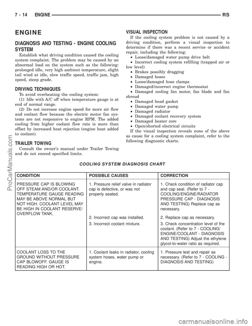
DIAGNOSIS AND TESTING - ENGINE COOLING
SYSTEM
Establish what driving condition caused the cooling
system complaint. The problem may be caused by an
abnormal load on the system such as the following:
prolonged idle, very high ambient temperature, slight
tail wind at idle, slow traffic speed, traffic jam, high
speed, steep grade.
DRIVING TECHNIQUES
To avoid overheating the cooling system:
(1) Idle with A/C off when temperature gauge is at
end of normal range.
(2) Do not increase engine speed for more air flow
and coolant flow because the electric motor fan sys-
tems are not responsive to engine RPM. The added
cooling from higher coolant flow rate is more than
offset by increased heat rejection (engine heat added
to coolant).
TRAILER TOWING
Consult the owner's manual under Trailer Towing
and do not exceed specified limits.
VISUAL INSPECTION
If the cooling system problem is not caused by a
driving condition, perform a visual inspection to
determine if there was a recent service or accident
repair, including the following:
²Loose/damaged water pump drive belt
²Incorrect cooling system refilling (trapped air or
low level)
²Brakes possibly dragging
²Damaged hoses
²Loose/damaged hose clamps
²Damaged/incorrect engine thermostat
²Damaged cooling fan motor, fan blade and fan
shroud
²Damaged head gasket
²Damaged water pump
²Damaged radiator
²Damaged coolant recovery system
²Damaged heater core
²Open/shorted electrical circuits
If the visual inspection reveals none of the above
as cause for a cooling system complaint, refer to the
following diagnostic charts.
COOLING SYSTEM DIAGNOSIS CHART
CONDITION POSSIBLE CAUSES CORRECTION
PRESSURE CAP IS BLOWING
OFF STEAM AND/OR COOLANT.
TEMPERATURE GAUGE READING
MAY BE ABOVE NORMAL BUT
NOT HIGH. COOLANT LEVEL MAY
BE HIGH IN COOLANT RESERVE/
OVERFLOW TANK.1. Pressure relief valve in radiator
cap is defective, or was not
properly seated.1. Check condition of radiator cap
and cap seal. (Refer to 7 -
COOLING/ENGINE/RADIATOR
PRESSURE CAP - DIAGNOSIS
AND TESTING) Replace cap as
necessary.
2. Incorrect cap was installed. 2. Replace cap as necessary.
3. Incorrect coolant mixture. 3. Check concentration level of the
coolant. (Refer to 7 - COOLING/
ENGINE/COOLANT - DIAGNOSIS
AND TESTING) Adjust the ethylene
glycol-to-water ratio as required.
COOLANT LOSS TO THE
GROUND WITHOUT PRESSURE
CAP BLOWOFF. GAUGE IS
READING HIGH OR HOT.1. Coolant leaks in radiator, cooling
system hoses, water pump or
engine.1. Pressure test and repair as
necessary. (Refer to 7 - COOLING -
DIAGNOSIS AND TESTING)
7 - 14 ENGINERS
ProCarManuals.com
Page 308 of 2321
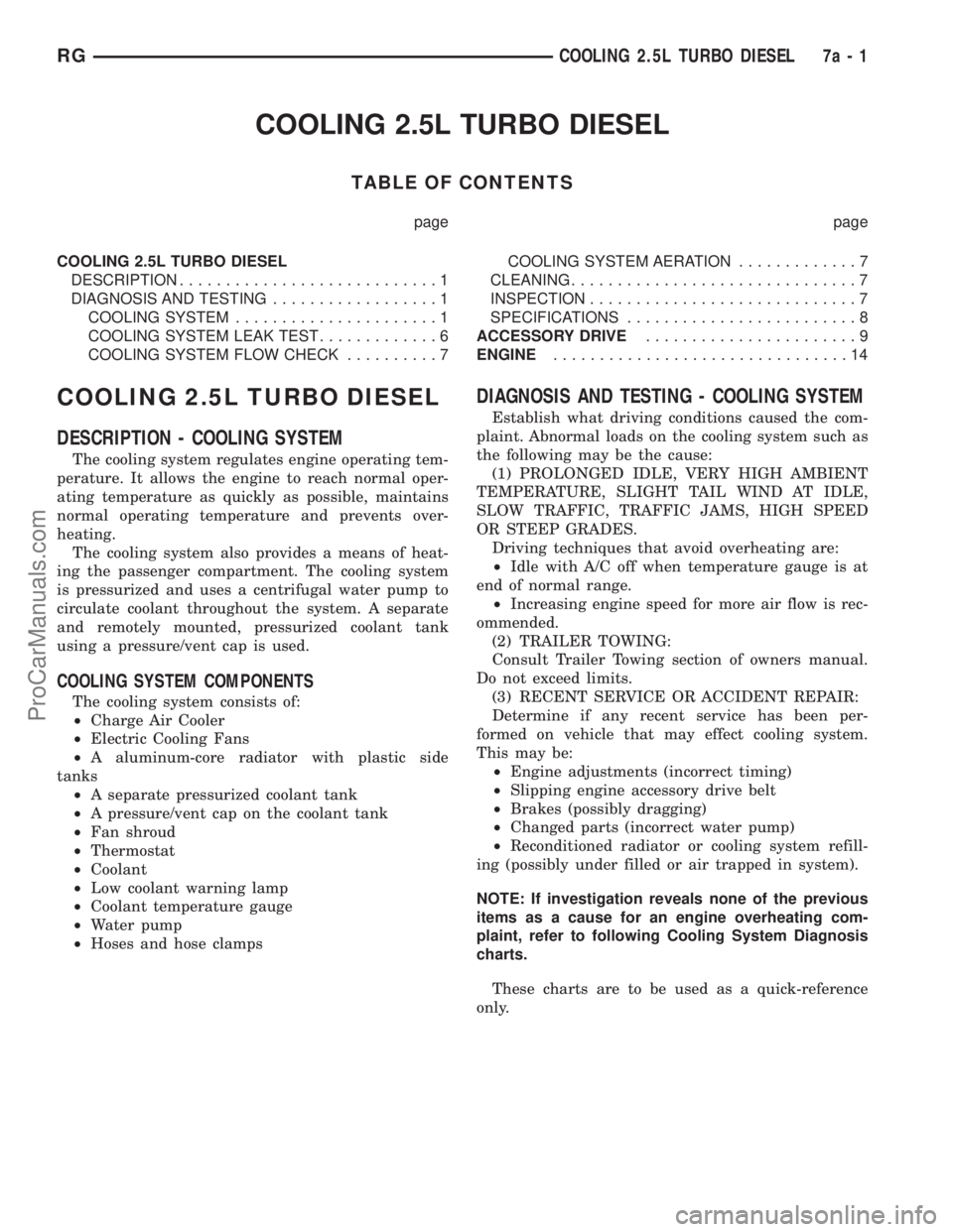
COOLING 2.5L TURBO DIESEL
TABLE OF CONTENTS
page page
COOLING 2.5L TURBO DIESEL
DESCRIPTION............................1
DIAGNOSIS AND TESTING..................1
COOLING SYSTEM......................1
COOLING SYSTEM LEAK TEST.............6
COOLING SYSTEM FLOW CHECK..........7COOLING SYSTEM AERATION.............7
CLEANING...............................7
INSPECTION.............................7
SPECIFICATIONS.........................8
ACCESSORY DRIVE.......................9
ENGINE................................14
COOLING 2.5L TURBO DIESEL
DESCRIPTION - COOLING SYSTEM
The cooling system regulates engine operating tem-
perature. It allows the engine to reach normal oper-
ating temperature as quickly as possible, maintains
normal operating temperature and prevents over-
heating.
The cooling system also provides a means of heat-
ing the passenger compartment. The cooling system
is pressurized and uses a centrifugal water pump to
circulate coolant throughout the system. A separate
and remotely mounted, pressurized coolant tank
using a pressure/vent cap is used.
COOLING SYSTEM COMPONENTS
The cooling system consists of:
²Charge Air Cooler
²Electric Cooling Fans
²A aluminum-core radiator with plastic side
tanks
²A separate pressurized coolant tank
²A pressure/vent cap on the coolant tank
²Fan shroud
²Thermostat
²Coolant
²Low coolant warning lamp
²Coolant temperature gauge
²Water pump
²Hoses and hose clamps
DIAGNOSIS AND TESTING - COOLING SYSTEM
Establish what driving conditions caused the com-
plaint. Abnormal loads on the cooling system such as
the following may be the cause:
(1) PROLONGED IDLE, VERY HIGH AMBIENT
TEMPERATURE, SLIGHT TAIL WIND AT IDLE,
SLOW TRAFFIC, TRAFFIC JAMS, HIGH SPEED
OR STEEP GRADES.
Driving techniques that avoid overheating are:
²Idle with A/C off when temperature gauge is at
end of normal range.
²Increasing engine speed for more air flow is rec-
ommended.
(2) TRAILER TOWING:
Consult Trailer Towing section of owners manual.
Do not exceed limits.
(3) RECENT SERVICE OR ACCIDENT REPAIR:
Determine if any recent service has been per-
formed on vehicle that may effect cooling system.
This may be:
²Engine adjustments (incorrect timing)
²Slipping engine accessory drive belt
²Brakes (possibly dragging)
²Changed parts (incorrect water pump)
²Reconditioned radiator or cooling system refill-
ing (possibly under filled or air trapped in system).
NOTE: If investigation reveals none of the previous
items as a cause for an engine overheating com-
plaint, refer to following Cooling System Diagnosis
charts.
These charts are to be used as a quick-reference
only.
RGCOOLING 2.5L TURBO DIESEL7a-1
ProCarManuals.com
Page 310 of 2321
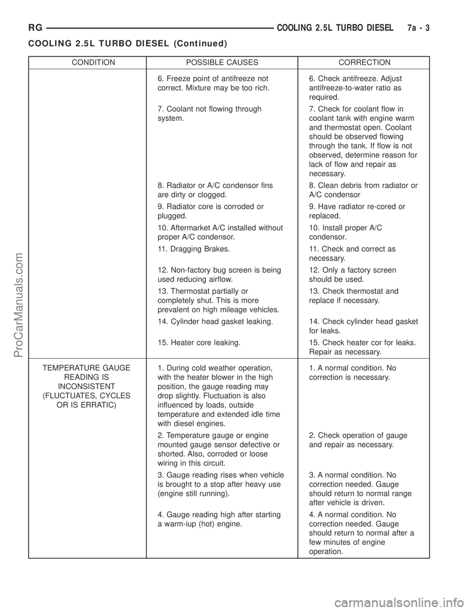
CONDITION POSSIBLE CAUSES CORRECTION
6. Freeze point of antifreeze not
correct. Mixture may be too rich.6. Check antifreeze. Adjust
antifreeze-to-water ratio as
required.
7. Coolant not flowing through
system.7. Check for coolant flow in
coolant tank with engine warm
and thermostat open. Coolant
should be observed flowing
through the tank. If flow is not
observed, determine reason for
lack of flow and repair as
necessary.
8. Radiator or A/C condensor fins
are dirty or clogged.8. Clean debris from radiator or
A/C condensor
9. Radiator core is corroded or
plugged.9. Have radiator re-cored or
replaced.
10. Aftermarket A/C installed without
proper A/C condensor.10. Install proper A/C
condensor.
11. Dragging Brakes. 11. Check and correct as
necessary.
12. Non-factory bug screen is being
used reducing airflow.12. Only a factory screen
should be used.
13. Thermostat partially or
completely shut. This is more
prevalent on high mileage vehicles.13. Check thermostat and
replace if necessary.
14. Cylinder head gasket leaking. 14. Check cylinder head gasket
for leaks.
15. Heater core leaking. 15. Check heater cor for leaks.
Repair as necessary.
TEMPERATURE GAUGE
READING IS
INCONSISTENT
(FLUCTUATES, CYCLES
OR IS ERRATIC)1. During cold weather operation,
with the heater blower in the high
position, the gauge reading may
drop slightly. Fluctuation is also
influenced by loads, outside
temperature and extended idle time
with diesel engines.1. A normal condition. No
correction is necessary.
2. Temperature gauge or engine
mounted gauge sensor defective or
shorted. Also, corroded or loose
wiring in this circuit.2. Check operation of gauge
and repair as necessary.
3. Gauge reading rises when vehicle
is brought to a stop after heavy use
(engine still running).3. A normal condition. No
correction needed. Gauge
should return to normal range
after vehicle is driven.
4. Gauge reading high after starting
a warm-iup (hot) engine.4. A normal condition. No
correction needed. Gauge
should return to normal after a
few minutes of engine
operation.
RGCOOLING 2.5L TURBO DIESEL7a-3
COOLING 2.5L TURBO DIESEL (Continued)
ProCarManuals.com
Page 363 of 2321
²Front Fog Lamp Relay Actuation
²Front and Rear Blower Motor Relay Actuation
²Accessory Relay Actuation
²Electronic Back Light (EBL) Rear Defogger
²Horn Relay Actuation
²Park Lamp Relay Actuation
²Name Brand Speaker (NBS) Relay Actuation
²Headlamp Washer Relay Actuation
²Diesel Cabin Heater (Diesel Engine Vehicles)
The following inputs areReceived/Monitoredby
the Front Control Module:
²B+ Connection Detection
²Ambient Temperature Sensing
²Right/Left Park Lamp Outage
²Ignition Switch Start Only
²Ignition Switch Run and Start Only
²Washer Fluid Level
²Windshield Wiper Park
²Brake Fluid Level
²Back-Up switch
²Stop Lamp Sense
²Engine Crank Signal (Diesel Engine Vehicles)
²Horn Input
DIAGNOSIS AND TESTING - FRONT CONTROL
MODULE
The front control module is a printed circuit board
based module with a on-board micro-processor. The
front control module interfaces with other electronic
modules in the vehicle via the Programmable Com-
munications Interface (PCI) data bus (J1850). In
order to obtain conclusive testing the Programmable
Communications Interface (PCI) data bus network
and all of the electronic modules that provide inputs
to, or receive outputs from the front control module
must be checked. All PCI (J1850) communication
faults must be resolved prior to further diagnosing
any front control module related issues.
The front control module was designed to be diag-
nosed with an appropriate diagnostic scan tool, such
as the DRB IIIt. The most reliable, efficient, and
accurate means to diagnose the front control module
requires the use of a DRB IIItscan tool and the
proper Body Diagnostic Procedures manual.
Before any testing of the front control module is
attempted, the battery should be fully charged and
all wire harness and ground connections inspected
around the affected areas on the vehicle.
REMOVAL
(1) Disconnect the positive and negative battery
cables from the battery.
(2) Remove the battery from the vehicle. Refer to
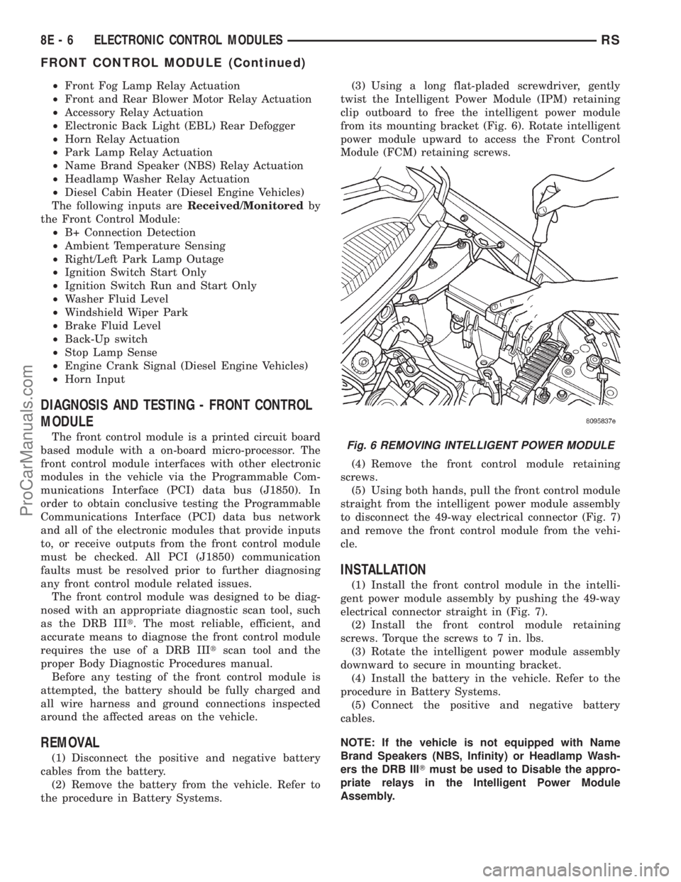
the procedure in Battery Systems.(3) Using a long flat-pladed screwdriver, gently
twist the Intelligent Power Module (IPM) retaining
clip outboard to free the intelligent power module
from its mounting bracket (Fig. 6). Rotate intelligent
power module upward to access the Front Control
Module (FCM) retaining screws.
(4) Remove the front control module retaining
screws.
(5) Using both hands, pull the front control module
straight from the intelligent power module assembly
to disconnect the 49-way electrical connector (Fig. 7)
and remove the front control module from the vehi-
cle.
INSTALLATION
(1) Install the front control module in the intelli-
gent power module assembly by pushing the 49-way
electrical connector straight in (Fig. 7).
(2) Install the front control module retaining
screws. Torque the screws to 7 in. lbs.
(3) Rotate the intelligent power module assembly
downward to secure in mounting bracket.
(4) Install the battery in the vehicle. Refer to the
procedure in Battery Systems.
(5) Connect the positive and negative battery
cables.
NOTE: If the vehicle is not equipped with Name
Brand Speakers (NBS, Infinity) or Headlamp Wash-
ers the DRB IIITmust be used to Disable the appro-
priate relays in the Intelligent Power Module
Assembly.
Fig. 6 REMOVING INTELLIGENT POWER MODULE
8E - 6 ELECTRONIC CONTROL MODULESRS
FRONT CONTROL MODULE (Continued)
ProCarManuals.com
Page 419 of 2321
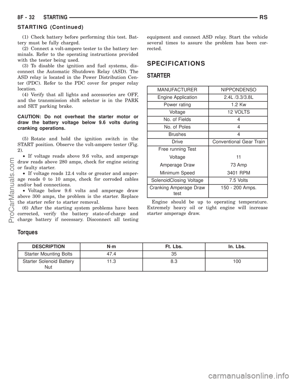
(1) Check battery before performing this test. Bat-
tery must be fully charged.
(2) Connect a volt-ampere tester to the battery ter-
minals. Refer to the operating instructions provided
with the tester being used.
(3) To disable the ignition and fuel systems, dis-
connect the Automatic Shutdown Relay (ASD). The
ASD relay is located in the Power Distribution Cen-
ter (PDC). Refer to the PDC cover for proper relay
location.
(4) Verify that all lights and accessories are OFF,
and the transmission shift selector is in the PARK
and SET parking brake.
CAUTION: Do not overheat the starter motor or
draw the battery voltage below 9.6 volts during
cranking operations.
(5) Rotate and hold the ignition switch in the
START position. Observe the volt-ampere tester (Fig.
2).
²If voltage reads above 9.6 volts, and amperage
draw reads above 280 amps, check for engine seizing
or faulty starter.
²If voltage reads 12.4 volts or greater and amper-
age reads 0 to 10 amps, check for corroded cables
and/or bad connections.
²Voltage below 9.6 volts and amperage draw
above 300 amps, the problem is the starter. Replace
the starter refer to starter removal.
(6) After the starting system problems have been
corrected, verify the battery state-of-charge and
charge battery if necessary. Disconnect all testingequipment and connect ASD relay. Start the vehicle
several times to assure the problem has been cor-
rected.
SPECIFICATIONS
STARTER
MANUFACTURER NIPPONDENSO
Engine Application 2.4L /3.3/3.8L
Power rating 1.2 Kw
Voltage 12 VOLTS
No. of Fields 4
No. of Poles 4
Brushes 4
Drive Conventional Gear Train
Free running Test
Voltage 11
Amperage Draw 73 Amp
Minimum Speed 3401 RPM
SolenoidClosing Voltage 7.5 Volts
Cranking Amperage Draw
test150 - 200 Amps.
Engine should be up to operating temperature.
Extremely heavy oil or tight engine will increase
starter amperage draw.
Torques
DESCRIPTION N´m Ft. Lbs. In. Lbs.
Starter Mounting Bolts 47.4 35
Starter Solenoid Battery
Nut11.3 8.3 100
8F - 32 STARTINGRS
STARTING (Continued)
ProCarManuals.com
Page 474 of 2321
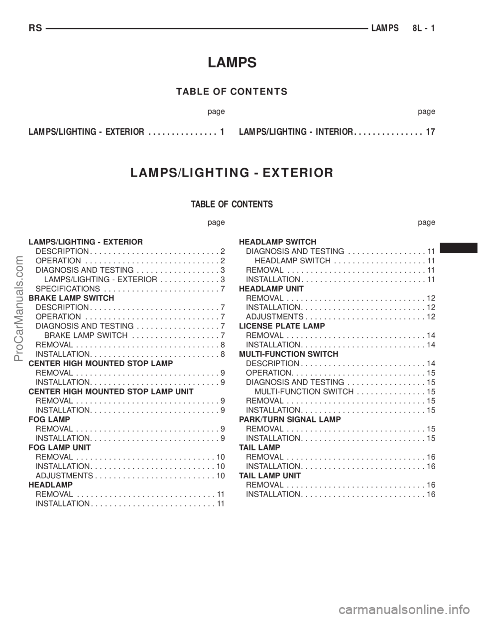
LAMPS
TABLE OF CONTENTS
page page
LAMPS/LIGHTING - EXTERIOR............... 1LAMPS/LIGHTING - INTERIOR............... 17
LAMPS/LIGHTING - EXTERIOR
TABLE OF CONTENTS
page page
LAMPS/LIGHTING - EXTERIOR
DESCRIPTION............................2
OPERATION.............................2
DIAGNOSIS AND TESTING..................3
LAMPS/LIGHTING - EXTERIOR.............3
SPECIFICATIONS.........................7
BRAKE LAMP SWITCH
DESCRIPTION............................7
OPERATION.............................7
DIAGNOSIS AND TESTING..................7
BRAKE LAMP SWITCH...................7
REMOVAL...............................8
INSTALLATION............................8
CENTER HIGH MOUNTED STOP LAMP
REMOVAL...............................9
INSTALLATION............................9
CENTER HIGH MOUNTED STOP LAMP UNIT
REMOVAL...............................9
INSTALLATION............................9
FOG LAMP
REMOVAL...............................9
INSTALLATION............................9
FOG LAMP UNIT
REMOVAL..............................10
INSTALLATION...........................10
ADJUSTMENTS..........................10
HEADLAMP
REMOVAL..............................11
INSTALLATION...........................11HEADLAMP SWITCH
DIAGNOSIS AND TESTING.................11
HEADLAMP SWITCH....................11
REMOVAL..............................11
INSTALLATION...........................11
HEADLAMP UNIT
REMOVAL..............................12
INSTALLATION...........................12
ADJUSTMENTS..........................12
LICENSE PLATE LAMP
REMOVAL..............................14
INSTALLATION...........................14
MULTI-FUNCTION SWITCH
DESCRIPTION...........................14
OPERATION.............................15
DIAGNOSIS AND TESTING.................15
MULTI-FUNCTION SWITCH...............15
REMOVAL..............................15
INSTALLATION...........................15
PARK/TURN SIGNAL LAMP
REMOVAL..............................15
INSTALLATION...........................15
TAIL LAMP
REMOVAL..............................16
INSTALLATION...........................16
TAIL LAMP UNIT
REMOVAL..............................16
INSTALLATION...........................16
RSLAMPS8L-1
ProCarManuals.com
Page 479 of 2321
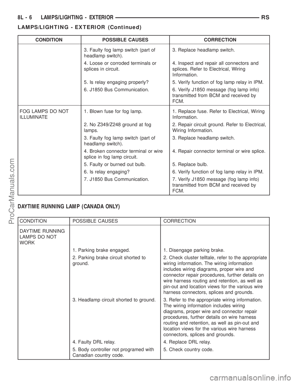
CONDITION POSSIBLE CAUSES CORRECTION
3. Faulty fog lamp switch (part of
headlamp switch).3. Replace headlamp switch.
4. Loose or corroded terminals or
splices in circuit.4. Inspect and repair all connectors and
splices. Refer to Electrical, Wiring
Information.
5. Is relay engaging properly? 5. Verify function of fog lamp relay in IPM.
6. J1850 Bus Communication. 6. Verify J1850 message (fog lamp info)
transmitted from BCM and received by
FCM.
FOG LAMPS DO NOT
ILLUMINATE1. Blown fuse for fog lamp. 1. Replace fuse. Refer to Electrical, Wiring
Information.
2. No Z349/Z248 ground at fog
lamps.2. Repair circuit ground. Refer to Electrical,
Wiring Information.
3. Faulty fog lamp switch (part of
headlamp switch).3. Replace headlamp switch.
4. Broken connector terminal or wire
splice in fog lamp circuit.4. Repair connector terminal or wire splice.
5. Faulty or burned out bulb. 5. Replace bulb.
6. Is relay engaging? 6. Verify function of fog lamp relay in IPM.
7. J1850 Bus Communication. 7. Verify J1850 message (fog lamp info)
transmitted from BCM and received by
FCM.
DAYTIME RUNNING LAMP (CANADA ONLY)
CONDITION POSSIBLE CAUSES CORRECTION
DAYTIME RUNNING
LAMPS DO NOT
WORK
1. Parking brake engaged. 1. Disengage parking brake.
2. Parking brake circuit shorted to
ground.2. Check cluster telltale, refer to the appropriate
wiring information. The wiring information
includes wiring diagrams, proper wire and
connector repair procedures, further details on
wire harness routing and retention, as well as
pin-out and location views for the various wire
harness connectors, splices and grounds.
3. Headlamp circuit shorted to ground. 3. Refer to the appropriate wiring information.
The wiring information includes wiring
diagrams, proper wire and connector repair
procedures, further details on wire harness
routing and retention, as well as pin-out and
location views for the various wire harness
connectors, splices and grounds.
4. Faulty DRL relay. 4. Replace DRL relay.
5. Body controller not programed with
Canadian country code.5. Check country code.
8L - 6 LAMPS/LIGHTING - EXTERIORRS
LAMPS/LIGHTING - EXTERIOR (Continued)
ProCarManuals.com
Page 480 of 2321
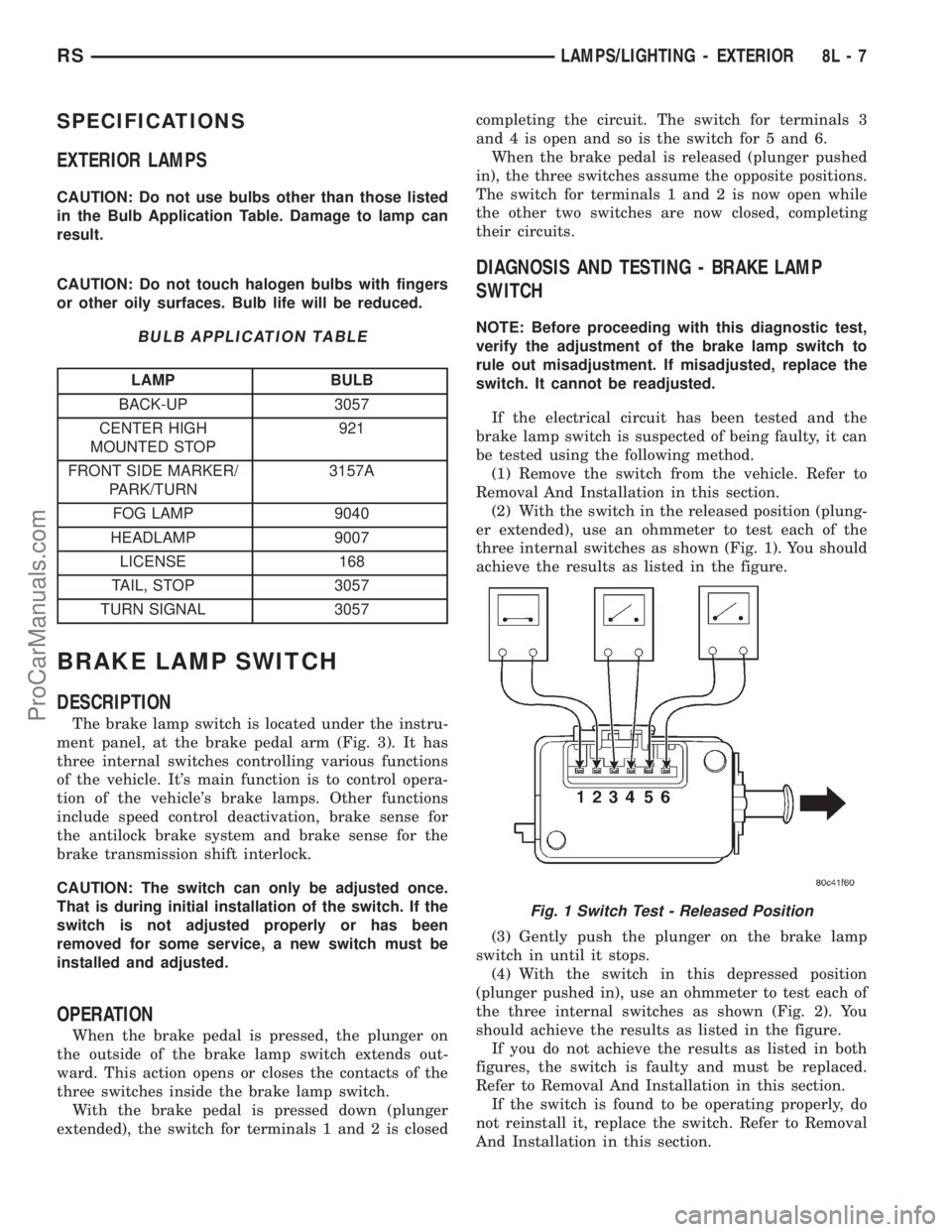
SPECIFICATIONS
EXTERIOR LAMPS
CAUTION: Do not use bulbs other than those listed
in the Bulb Application Table. Damage to lamp can
result.
CAUTION: Do not touch halogen bulbs with fingers
or other oily surfaces. Bulb life will be reduced.
BULB APPLICATION TABLE
LAMP BULB
BACK-UP 3057
CENTER HIGH
MOUNTED STOP921
FRONT SIDE MARKER/
PARK/TURN3157A
FOG LAMP 9040
HEADLAMP 9007
LICENSE 168
TAIL, STOP 3057
TURN SIGNAL 3057
BRAKE LAMP SWITCH
DESCRIPTION
The brake lamp switch is located under the instru-
ment panel, at the brake pedal arm (Fig. 3). It has
three internal switches controlling various functions
of the vehicle. It's main function is to control opera-
tion of the vehicle's brake lamps. Other functions
include speed control deactivation, brake sense for
the antilock brake system and brake sense for the
brake transmission shift interlock.
CAUTION: The switch can only be adjusted once.
That is during initial installation of the switch. If the
switch is not adjusted properly or has been
removed for some service, a new switch must be
installed and adjusted.
OPERATION
When the brake pedal is pressed, the plunger on
the outside of the brake lamp switch extends out-
ward. This action opens or closes the contacts of the
three switches inside the brake lamp switch.
With the brake pedal is pressed down (plunger
extended), the switch for terminals 1 and 2 is closedcompleting the circuit. The switch for terminals 3
and 4 is open and so is the switch for 5 and 6.
When the brake pedal is released (plunger pushed
in), the three switches assume the opposite positions.
The switch for terminals 1 and 2 is now open while
the other two switches are now closed, completing
their circuits.
DIAGNOSIS AND TESTING - BRAKE LAMP
SWITCH
NOTE: Before proceeding with this diagnostic test,
verify the adjustment of the brake lamp switch to
rule out misadjustment. If misadjusted, replace the
switch. It cannot be readjusted.
If the electrical circuit has been tested and the
brake lamp switch is suspected of being faulty, it can
be tested using the following method.
(1) Remove the switch from the vehicle. Refer to
Removal And Installation in this section.
(2) With the switch in the released position (plung-
er extended), use an ohmmeter to test each of the
three internal switches as shown (Fig. 1). You should
achieve the results as listed in the figure.
(3) Gently push the plunger on the brake lamp
switch in until it stops.
(4) With the switch in this depressed position
(plunger pushed in), use an ohmmeter to test each of
the three internal switches as shown (Fig. 2). You
should achieve the results as listed in the figure.
If you do not achieve the results as listed in both
figures, the switch is faulty and must be replaced.
Refer to Removal And Installation in this section.
If the switch is found to be operating properly, do
not reinstall it, replace the switch. Refer to Removal
And Installation in this section.
Fig. 1 Switch Test - Released Position
RSLAMPS/LIGHTING - EXTERIOR8L-7
ProCarManuals.com