2001 DODGE TOWN AND COUNTRY brake light
[x] Cancel search: brake lightPage 110 of 2321
DIFFERENTIAL & DRIVELINE
TABLE OF CONTENTS
page page
HALF SHAFT - FRONT.....................1
HALF SHAFT - REAR.....................16PROPELLER SHAFT......................24
REAR DRIVELINE MODULE................26
HALF SHAFT - FRONT
TABLE OF CONTENTS
page page
HALF SHAFT - FRONT
DESCRIPTION............................1
DIAGNOSIS AND TESTING..................1
HALF SHAFT...........................1
REMOVAL...............................2
INSTALLATION............................5
SPECIFICATIONS.........................7
CV BOOT - INNER
REMOVAL...............................7INSTALLATION............................8
CV BOOT - OUTER
REMOVAL..............................11
INSTALLATION...........................12
OUTER CV JOINT BEARING SHIELD
REMOVAL..............................14
INSTALLATION...........................14
HALF SHAFT - FRONT
DESCRIPTION
All vehicles use an unequal length half shaft sys-
tem (Fig. 1).
The left half shaft uses a tuned rubber damper
weight. When replacing the left half shaft, be sure
the replacement half shaft has the same damper
weight as the original.
All half shaft assemblies use the same type of
inner and outer joints. The inner joint of both half
shaft assemblies is a tripod joint, and the outer joint
of both half shaft assemblies is a Rzeppa joint. Both
tripod joints and Rzeppa joints are true constant
velocity (CV) joint assemblies. The inner tripod joint
allows for the changes in half shaft length through
the jounce and rebound travel of the front suspen-
sion.
On vehicles equipped with ABS brakes, the outer
CV joint is equipped with a tone wheel used to deter-
mine vehicle speed for ABS brake operation.
The inner tripod joint of both half shafts is splined
into the transaxle side gears. The inner tripod joints
are retained in the side gears of the transaxle usinga snap ring located in the stub shaft of the tripod
joint. The outer CV joint has a stub shaft that is
splined into the wheel hub and retained by a steel
hub nut.
DIAGNOSIS AND TESTING - HALF SHAFT
VEHICLE INSPECTION
(1) Check for grease in the vicinity of the inboard
tripod joint and outboard CV joint; this is a sign of
inner or outer joint seal boot or seal boot clamp dam-
age.
(2) A light film of grease may appear on the right
inner tripod joint seal boot; this is considered normal
and should not require replacement of the seal boot.
NOISE AND/OR VIBRATION IN TURNS
A clicking noise and/or a vibration in turns could
be caused by one of the following conditions:
²Damaged outer CV or inner tripod joint seal
boot or seal boot clamps. This will result in the loss
and/or contamination of the joint grease, resulting in
inadequate lubrication of the joint.
RSDIFFERENTIAL & DRIVELINE3-1
ProCarManuals.com
Page 125 of 2321
HALF SHAFT - REAR
TABLE OF CONTENTS
page page
HALF SHAFT - REAR
DESCRIPTION...........................16
DIAGNOSIS AND TESTING.................16
HALF SHAFT..........................16
REMOVAL..............................16INSTALLATION...........................17
SPECIFICATIONS........................18
CV BOOT - INNER/OUTER
REMOVAL..............................18
INSTALLATION...........................20
HALF SHAFT - REAR
DESCRIPTION
The inner and outer joints of both half shaft
assemblies are tripod joints. The tripod joints are
true constant velocity (CV) joint assemblies, which
allow for the changes in half shaft length through
the jounce and rebound travel of the rear suspension.
On vehicles equipped with ABS brakes, the outer
CV joint is equipped with a tone wheel used to deter-
mine vehicle speed for ABS brake operation.
The inner tripod joint of both half shafts is bolted
rear differential assembly's output flanges. The outer
CV joint has a stub shaft that is splined into the
wheel hub and retained by a steel hub nut.
DIAGNOSIS AND TESTING - HALF SHAFT
VEHICLE INSPECTION
(1) Check for grease in the vicinity of the inboard
tripod joint and outboard CV joint; this is a sign of
inner or outer joint seal boot or seal boot clamp dam-
age.
(2) A light film of grease may appear on the right
inner tripod joint seal boot; this is considered normal
and should not require replacement of the seal boot.
NOISE AND/OR VIBRATION IN TURNS
A clicking noise and/or a vibration in turns could
be caused by one of the following conditions:
²Damaged outer CV or inner tripod joint seal
boot or seal boot clamps. This will result in the loss
and/or contamination of the joint grease, resulting in
inadequate lubrication of the joint.
²Noise may also be caused by another component
of the vehicle coming in contact with the half shafts.
CLUNKING NOISE DURING ACCELERATION
This noise may be a result of one of the following
conditions:²A torn seal boot on the inner or outer joint of the
half shaft assembly.
²A loose or missing clamp on the inner or outer
joint of the half shaft assembly.
²A damaged or worn half shaft CV joint.
SHUDDER OR VIBRATION DURING ACCELERATION
This problem could be a result of:
²A worn or damaged half shaft inner tripod joint.
²A sticking tripod joint spider assembly (inner tri-
pod joint only).
²Improper wheel alignment. (Refer to 2 - SUS-
PENSION/WHEEL ALIGNMENT - STANDARD
PROCEDURE)
VIBRATION AT HIGHWAY SPEEDS
This problem could be a result of:
²Foreign material (mud, etc.) packed on the back-
side of the wheel(s).
²Out of balance tires or wheels. (Refer to 22 -
TIRES/WHEELS - STANDARD PROCEDURE)
²Improper tire and/or wheel runout. (Refer to 22 -
TIRES/WHEELS - DIAGNOSIS AND TESTING)
REMOVAL
(1) Lift vehicle on hoist so that the wheels hang
freely.
(2) Remove rear wheel.
(3) Remove cotter pin, nut lock, and wave washer
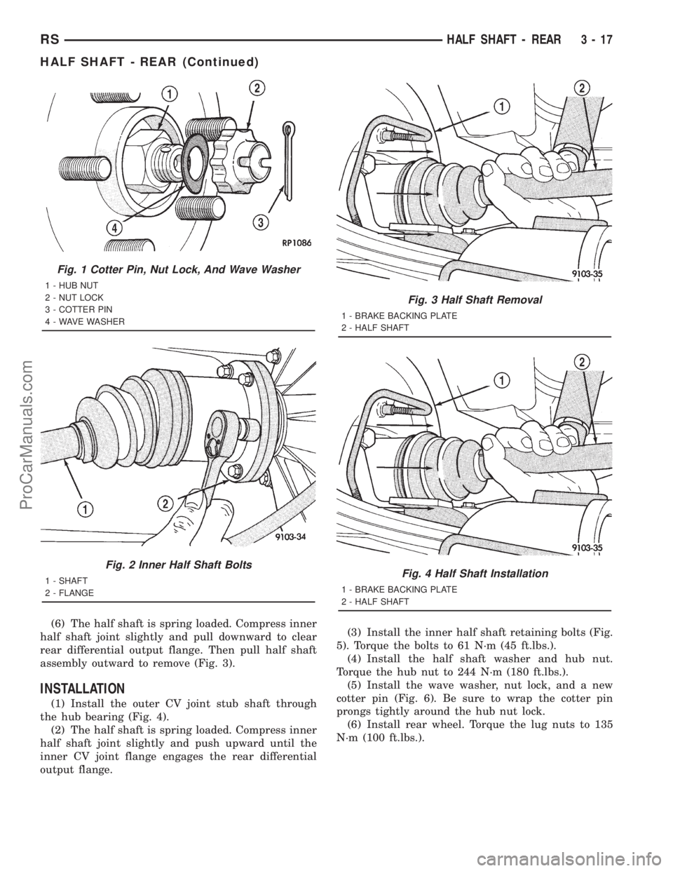
(Fig. 1).
(4) Remove hub nut and washer.
CAUTION: The half shaft outer CV joint, when
installed, acts as a bolt and secures the hub/bear-
ing assembly. If the vehicle is to be supported or
moved on its wheels, install and torque a bolt
through the hub. This will ensure that the hub/bear-
ing assembly cannot loosen.
(5) Remove inner half shaft retaining bolts (Fig. 2).
3 - 16 HALF SHAFT - REARRS
ProCarManuals.com
Page 126 of 2321
(6) The half shaft is spring loaded. Compress inner
half shaft joint slightly and pull downward to clear
rear differential output flange. Then pull half shaft
assembly outward to remove (Fig. 3).
INSTALLATION
(1) Install the outer CV joint stub shaft through
the hub bearing (Fig. 4).
(2) The half shaft is spring loaded. Compress inner
half shaft joint slightly and push upward until the
inner CV joint flange engages the rear differential
output flange.(3) Install the inner half shaft retaining bolts (Fig.
5). Torque the bolts to 61 N´m (45 ft.lbs.).
(4) Install the half shaft washer and hub nut.
Torque the hub nut to 244 N´m (180 ft.lbs.).
(5) Install the wave washer, nut lock, and a new
cotter pin (Fig. 6). Be sure to wrap the cotter pin
prongs tightly around the hub nut lock.
(6) Install rear wheel. Torque the lug nuts to 135
N´m (100 ft.lbs.).
Fig. 1 Cotter Pin, Nut Lock, And Wave Washer
1 - HUB NUT
2 - NUT LOCK
3 - COTTER PIN
4 - WAVE WASHER
Fig. 2 Inner Half Shaft Bolts
1 - SHAFT
2 - FLANGE
Fig. 3 Half Shaft Removal
1 - BRAKE BACKING PLATE
2 - HALF SHAFT
Fig. 4 Half Shaft Installation
1 - BRAKE BACKING PLATE
2 - HALF SHAFT
RSHALF SHAFT - REAR3-17
HALF SHAFT - REAR (Continued)
ProCarManuals.com
Page 161 of 2321
JUNCTION BLOCK
DESCRIPTION...........................32
OPERATION.............................32
REMOVAL..............................32
INSTALLATION...........................33
MASTER CYLINDER
DESCRIPTION...........................33
OPERATION.............................34
STANDARD PROCEDURE..................34
MASTER CYLINDER BLEEDING...........34
REMOVAL..............................34
DISASSEMBLY...........................35
ASSEMBLY.............................36
INSTALLATION...........................36
POWER BRAKE BOOSTER
DESCRIPTION...........................37
OPERATION.............................37
DIAGNOSIS AND TESTING.................38
POWER BRAKE BOOSTER...............38
REMOVAL..............................38
INSTALLATION...........................40
PROPORTIONING VALVE
DESCRIPTION...........................41
OPERATION.............................42
DIAGNOSIS AND TESTING.................42
PROPORTIONING VALVE (HEIGHT
SENSING).............................42
REMOVAL..............................43
INSTALLATION...........................43
ROTORS
DIAGNOSIS AND TESTING.................44BRAKE ROTOR........................44
STANDARD PROCEDURE..................47
BRAKE ROTOR MACHINING..............47
REMOVAL..............................48
INSTALLATION...........................48
SUPPORT PLATE - DRUM BRAKE
REMOVAL..............................48
INSTALLATION...........................49
WHEEL CYLINDERS
REMOVAL..............................50
INSPECTION............................50
INSTALLATION...........................50
PARKING BRAKE
DESCRIPTION...........................50
OPERATION.............................51
STANDARD PROCEDURE..................51
PARKING BRAKE AUTOMATIC ADJUSTER
MECHANISM RELEASE..................51
PARKING BRAKE AUTOMATIC ADJUSTER
RESET...............................51
LEVER - PARKING BRAKE
REMOVAL..............................52
INSTALLATION...........................53
SHOES - PARKING BRAKE
REMOVAL..............................53
INSTALLATION...........................58
ADJUSTMENTS..........................59
CABLES - PARKING BRAKE
REMOVAL..............................61
INSTALLATION...........................65
ADJUSTMENTS..........................66
BRAKES - BASE
DESCRIPTION - BASE BRAKES
The base brake system consists of the following
components:
²Brake pedal
²Power brake booster
²Master cylinder
²Brake tubes and hoses
²Proportioning valve (non-ABS vehicles only)
²Disc brakes
²Drum brakes
²Brake lamp switch
²Brake fluid level switch
²Parking brakes
Front disc brakes control the braking of the front
wheels; rear braking is controlled by rear drum
brakes or rear disc brakes depending on options.
The hydraulic brake system is diagonally split on
both the non-antilock braking systems and antilock
braking systems. That means the left front and right
rear brakes are on one hydraulic circuit and the right
front and left rear are on the other.For information on the brake lamp switch, (Refer
to 8 - ELECTRICAL/LAMPS/LIGHTING - EXTERI-
OR/BRAKE LAMP SWITCH - DESCRIPTION)
Vehicles equipped with the optional antilock brake
system (ABS) use a system designated Mark 20e. It
is available with or without traction control. This
system shares most base brake hardware used on
vehicles without ABS. ABS components are described
in detail in ANTILOCK BRAKE SYSTEM.
OPERATION - BASE BRAKES
When a vehicle needs to be stopped, the driver
applies the brake pedal. The brake pedal pushes the
input rod of the power brake booster into the booster.
The booster uses vacuum to ease pedal effort as force
is transferred through the booster to the master cyl-
inder. The booster's output rod pushes in the master
cylinder's primary and secondary pistons applying
hydraulic pressure through the chassis brake tubes
to the brakes at each tire and wheel assembly.
The parking brakes are foot-operated. When
applied, the parking brake lever pulls on cables that
actuate brake shoes at each rear wheel. These shoes
come in contact with a hub mounted drum (drum for
5 - 2 BRAKES - BASERS
ProCarManuals.com
Page 163 of 2321

RED BRAKE WARNING INDICATOR LAMP
CONDITION POSSIBLE CAUSES CORRECTION
RED BRAKE WARNING
LAMP ON1. Parking brake lever not fully
released.1. Release parking brake lever.
2. Parking brake warning lamp
switch on parking brake lever.2. Inspect and replace switch as necessary.
3. Brake fluid level low in reservoir. 3. Fill reservoir. Check entire system for
leaks. Repair or replace as required.
4. Brake fluid level switch. 4. Disconnect switch wiring connector. If
lamp goes out, replace switch.
5. Mechanical instrument cluster
(MIC) problem.5. Refer to appropriate Diagnostic
information.
6. Amber ABS Warning Indicator
Lamp also illuminated.6. Refer to appropriate Diagnostic
information.
BRAKE NOISE
CONDITION POSSIBLE CAUSES CORRECTION
CLICK OR SQUAWK ON
PEDAL APPLICATION1. Brake lamp switch. 1. Replace switch.
2. Brake Transmission Shift Interlock
Linkage.2. Lubricate BTSI linkage.
3. Pedal pivot bushings 3. Lubricate pivot bushings. Replace if
necessary.
DISC BRAKE CHIRP 1. Excessive brake rotor runout. 1. Follow brake rotor diagnosis and testing.
Correct as necessary.
2. Lack of lubricant on brake caliper
slides.2. Lubricate brake caliper slides.
3. Caliper/shoes not fully seated. 3. Reseat caliper/shoes.
DISC BRAKE RATTLE OR
CLUNK1. Broken or missing anti-rattle
spring clips on shoes.1. Replace brake shoes.
2. Caliper guide pins/bolts loose. 2. Tighten guide pins/bolts.
DISC BRAKE SQUEAK AT
LOW SPEED (WHILE
APPLYING LIGHT BRAKE
PEDAL EFFORT)1. Brake shoe linings. 1. Replace brake shoes.
DRUM BRAKE CHIRP 1. Lack of lubricant on brake shoe
support plate where shoes ride.1. Lubricate shoe contact areas on brake
shoe support plates.
DRUM BRAKE CLUNK 1. Drum(s) have threaded machined
braking surface.1. Reface or replace drake drums as
necessary.
DRUM BRAKE HOWL OR
MOAN1. Lack of lubricant on brake shoe
support plate where shoes ride and
at the anchor.1. Lubricate shoe contact areas on brake
shoe support plates and at the anchor.
2. Rear brake shoes. 2. Replace rear brake shoes.
DRUM BRAKE SCRAPING
OR WHIRRING1. ABS wheel speed sensor or tone
wheel.1. Inspect, correct or replace faulty
component(s).
5 - 4 BRAKES - BASERS
BRAKES - BASE (Continued)
ProCarManuals.com
Page 181 of 2321
(20) Road test vehicle. The automatic adjuster will
continue the brake adjustment during the road test
of the vehicle.
ADJUSTMENT - REAR DRUM BRAKE SHOES
NOTE: Normally, self-adjusting drum brakes do not
require manual brake shoe adjustment. Although, in
the event of a brake shoe replacement, it is advis-
able to make the initial adjustment manually to
speed up the adjusting time.
NOTE: Before raising the vehicle, verify the parking
brake lever is fully released.
(1) Raise the vehicle. (Refer to LUBRICATION &
MAINTENANCE/HOISTING - STANDARD PROCE-
DURE).
(2) Remove rubber plug from rear brake adjusting
hole in the rear brake support plate.
(3) Insert a thin screwdriver through the adjusting
hole in the support plate and against the star wheel
of the adjusting screw. Move handle of the tool
upward rotating the star wheel until a slight drag is
felt when tire and wheel assembly is rotated.
(4) Insert a second thin screwdriver or piece of
welding rod into brake adjusting hole and push the
adjusting lever out of engagement with the star
wheel.Care should be taken so as not to bend
adjusting lever or distort lever spring.
(5) While holding the adjusting lever out of
engagement, back off the star wheel just enough to
ensure a free wheel with no brake shoe drag.
(6) Repeat the above adjustment at the other rear
wheel.
(7) Install the adjusting hole rubber plugs back in
the rear brake support plates.
(8) Lower the vehicle.
DISC BRAKE CALIPERS -
FRONT
REMOVAL - FRONT DISC BRAKE CALIPER
(DISC/DISC BRAKES)
(1) Depress the brake pedal past its first inch of
travel and hold it in this position using a brake pedal
depressor (holding) tool. This is done to isolate the
master cylinder from the brake hydraulic system dis-
allowing the brake fluid to completely drain out of
the brake fluid reservoir.
(2) Raise the vehicle. (Refer to LUBRICATION &
MAINTENANCE/HOISTING - STANDARD PROCE-
DURE).
(3) Remove front wheel and tire assembly.(4) Remove the banjo bolt connecting the brake
hose to the brake caliper. There are two washers (one
on each side of the brake hose fitting) that will come
off with the banjo bolt. Discard these washers.
(5) Remove the 2 caliper guide pin bolts.
(6) Remove the brake caliper from the adapter.
REMOVAL - FRONT DISC BRAKE CALIPER
(DISC/DRUM BRAKES)
(1) Using a brake pedal holding tool, depress the
brake pedal past its first one inch of travel and hold
it in this position. This will isolate the master cylin-
der from the brake hydraulic system and will not
allow the brake fluid to drain out of the master cyl-
inder reservoir when the lines are opened.
(2) Raise the vehicle. Refer to HOISTING in
LUBRICATION AND MAINTENANCE.
(3) Remove the front tire and wheel assembly.
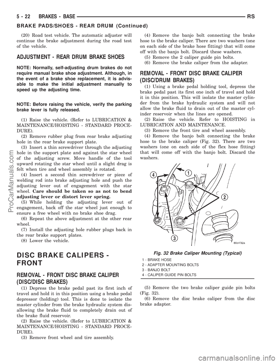
(4) Remove the banjo bolt connecting the brake
hose to the brake caliper (Fig. 32). There are two
washers (one on each side of the flex hose fitting)
that will come off with the banjo bolt. Discard the
washers.
(5) Remove the two brake caliper guide pin bolts
(Fig. 32).
(6) Remove the disc brake caliper from the disc
brake adapter.
Fig. 32 Brake Caliper Mounting (Typical)
1 - BRAKE HOSE
2 - ADAPTER MOUNTING BOLTS
3 - BANJO BOLT
4 - CALIPER GUIDE PIN BOLTS
5 - 22 BRAKES - BASERS
BRAKE PADS/SHOES - REAR DRUM (Continued)
ProCarManuals.com
Page 182 of 2321
DISASSEMBLY - CALIPER GUIDE PIN
BUSHINGS (DISC/DISC BRAKES)
Before disassembling the brake caliper, clean and
inspect it. Refer to CLEANING or INSPECTION in
this section.
(1) Using your fingers, collapse one side of the rub-
ber guide pin bushing. Pull the guide pin bushing out
the other side of the brake caliper mounting boss.
(2) Repeat this procedure on the remaining bush-
ing.
DISASSEMBLY - CALIPER PISTON AND SEAL
WARNING: UNDER NO CONDITION SHOULD HIGH
PRESSURE AIR EVER BE USED TO REMOVE A PIS-
TON FROM A CALIPER BORE. PERSONAL INJURY
COULD RESULT FROM SUCH A PRACTICE.
NOTE: Before disassembling the brake caliper,
clean and inspect it. Refer to CLEANING AND
INSPECTION in this section.
NOTE: The safest way to remove the piston from
the caliper bore is to use the hydraulic pressure of
the vehicle's brake system.
(1) Following the removal procedure in DISC
BRAKE SHOES found in this section, remove the
caliper from the brake rotor and hang the assembly
on a wire hook away from rotor and body of the vehi-
cle so brake fluid cannot get on these components.
Remove the brake shoes, and place a small piece of
wood between the piston and caliper fingers.
(2) Carefully depress the brake pedal to hydrauli-
cally push piston out of its bore. Once completed,
apply and hold down the brake pedal to any position
beyond the first inch of pedal travel using a brake
pedal holding tool. This will prevent the fluid in the
master cylinder reservoir from completely draining
out.
(3) Disconnect the brake fluid flex hose from the
caliper assembly and remove it from the vehicle.
CAUTION: Do not use excessive force when clamp-
ing caliper in vise. Excessive vise pressure will
cause bore distortion.(4) Mount the caliper in a vise equipped with pro-
tective jaws.
(5) Remove the piston dust boot from the caliper
and discard.
NOTE: Do not use a screw driver or other metal tool
for seal removal. Using such tools can scratch the
bore or leave burrs on the seal groove edges.
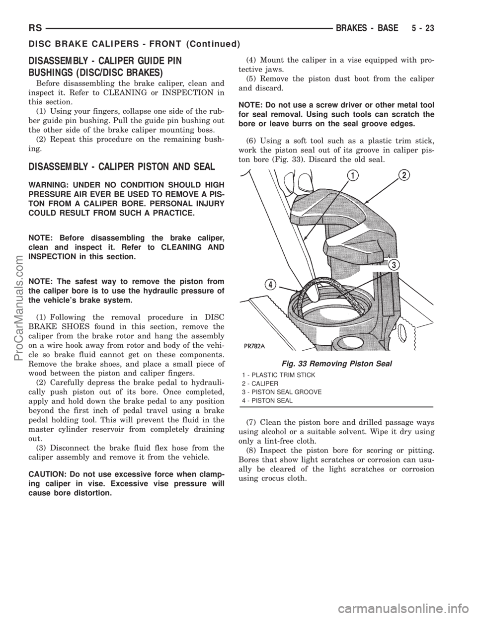
(6) Using a soft tool such as a plastic trim stick,
work the piston seal out of its groove in caliper pis-
ton bore (Fig. 33). Discard the old seal.
(7) Clean the piston bore and drilled passage ways
using alcohol or a suitable solvent. Wipe it dry using
only a lint-free cloth.
(8) Inspect the piston bore for scoring or pitting.
Bores that show light scratches or corrosion can usu-
ally be cleared of the light scratches or corrosion
using crocus cloth.
Fig. 33 Removing Piston Seal
1 - PLASTIC TRIM STICK
2 - CALIPER
3 - PISTON SEAL GROOVE
4 - PISTON SEAL
RSBRAKES - BASE5-23
DISC BRAKE CALIPERS - FRONT (Continued)
ProCarManuals.com
Page 186 of 2321
DISASSEMBLY - CALIPER PISTON AND SEAL
WARNING: UNDER NO CONDITION SHOULD HIGH
PRESSURE AIR EVER BE USED TO REMOVE A PIS-
TON FROM A CALIPER BORE. PERSONAL INJURY
COULD RESULT FROM SUCH A PRACTICE.
NOTE: Before disassembling the brake caliper,
clean and inspect it. Refer to CLEANING AND
INSPECTION in this section.
NOTE: The safest way to remove the piston from
the caliper bore is to use the hydraulic pressure of
the vehicle's brake system.
(1) Following the removal procedure in DISC
BRAKE SHOES found in this section, remove the
caliper from the brake rotor and hang the assembly
on a wire hook away from rotor and body of the vehi-
cle so brake fluid cannot get on these components.
Remove the brake shoes, and place a small piece of
wood between the piston and caliper fingers.
(2) Carefully depress the brake pedal to hydrauli-
cally push piston out of its bore. Once completed,
apply and hold down the brake pedal to any position
beyond the first inch of pedal travel using a brake
pedal holding tool. This will prevent the fluid in the
master cylinder reservoir from completely draining
out.(3) Disconnect the brake fluid flex hose from the
caliper assembly and remove it from the vehicle.
CAUTION: Do not use excessive force when clamp-
ing caliper in vise. Excessive vise pressure will
cause bore distortion.
(4) Mount the caliper in a vise equipped with pro-
tective jaws.
(5) Remove the piston dust boot from the caliper
and discard.
NOTE: Do not use a screw driver or other metal tool
for seal removal. Using such tools can scratch the
bore or leave burrs on the seal groove edges.
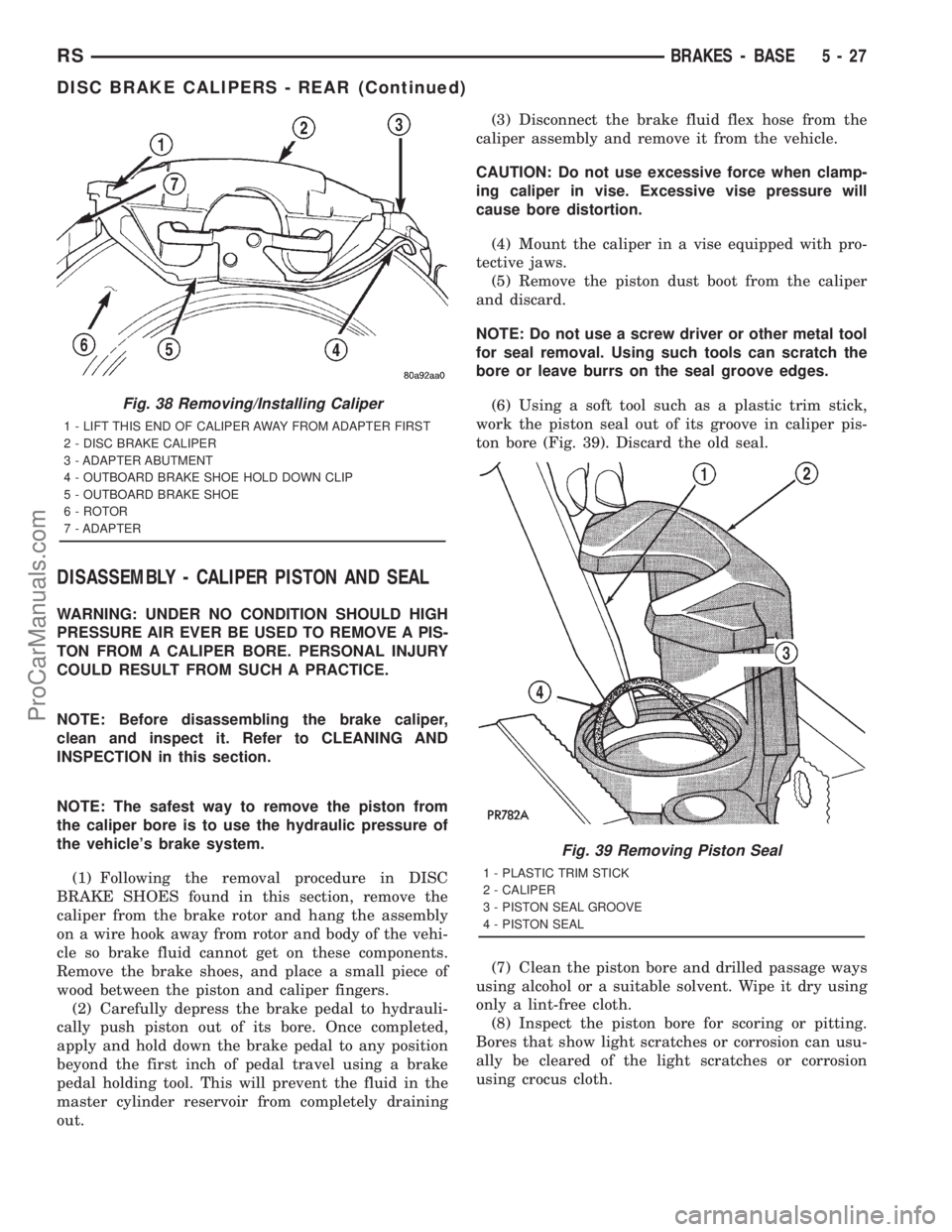
(6) Using a soft tool such as a plastic trim stick,
work the piston seal out of its groove in caliper pis-
ton bore (Fig. 39). Discard the old seal.
(7) Clean the piston bore and drilled passage ways
using alcohol or a suitable solvent. Wipe it dry using
only a lint-free cloth.
(8) Inspect the piston bore for scoring or pitting.
Bores that show light scratches or corrosion can usu-
ally be cleared of the light scratches or corrosion
using crocus cloth.
Fig. 38 Removing/Installing Caliper
1 - LIFT THIS END OF CALIPER AWAY FROM ADAPTER FIRST
2 - DISC BRAKE CALIPER
3 - ADAPTER ABUTMENT
4 - OUTBOARD BRAKE SHOE HOLD DOWN CLIP
5 - OUTBOARD BRAKE SHOE
6 - ROTOR
7 - ADAPTER
Fig. 39 Removing Piston Seal
1 - PLASTIC TRIM STICK
2 - CALIPER
3 - PISTON SEAL GROOVE
4 - PISTON SEAL
RSBRAKES - BASE5-27
DISC BRAKE CALIPERS - REAR (Continued)
ProCarManuals.com