2001 DODGE TOWN AND COUNTRY transmission fluid
[x] Cancel search: transmission fluidPage 183 of 2321
CLEANING - CALIPER
WARNING: DUST AND DIRT ACCUMULATING ON
BRAKE PARTS DURING NORMAL USE MAY CON-
TAIN ASBESTOS FIBERS FROM PRODUCTION OR
AFTERMARKET BRAKE LININGS. BREATHING
EXCESSIVE CONCENTRATIONS OF ASBESTOS
FIBERS CAN CAUSE SERIOUS BODILY HARM.
EXERCISE CARE WHEN SERVICING BRAKE
PARTS. DO NOT SAND OR GRIND BRAKE LINING
UNLESS EQUIPMENT USED IS DESIGNED TO CON-
TAIN THE DUST RESIDUE. DO NOT CLEAN BRAKE
PARTS WITH COMPRESSED AIR OR BY DRY
BRUSHING. CLEANING SHOULD BE DONE BY
DAMPENING THE BRAKE COMPONENTS WITH A
FINE MIST OF WATER, THEN WIPING THE BRAKE
COMPONENTS CLEAN WITH A DAMPENED CLOTH.
DISPOSE OF CLOTH AND ALL RESIDUE CONTAIN-
ING ASBESTOS FIBERS IN AN IMPERMEABLE
CONTAINER WITH THE APPROPRIATE LABEL. FOL-
LOW PRACTICES PRESCRIBED BY THE OCCUPA-
TIONAL SAFETY AND HEALTH ADMINISTRATION
(OSHA) AND THE ENVIRONMENTAL PROTECTION
AGENCY (EPA) FOR THE HANDLING, PROCESSING,
AND DISPOSING OF DUST OR DEBRIS THAT MAY
CONTAIN ASBESTOS FIBERS.
To clean or flush the internal passages of the brake
caliper, use fresh brake fluid or MopartNon-Chlori-
nated Brake Parts Cleaner. Never use gasoline, ker-
osene, alcohol, oil, transmission fluid or any fluid
containing mineral oil to clean the caliper. These flu-
ids will damage rubber cups and seals.
INSPECTION - CALIPER
Inspect the disc brake caliper for the following:
²Brake fluid leaks in and around boot area and
inboard lining
²Ruptures, brittleness or damage to the piston
dust boot
²Damaged, dry or brittle guide pin dust boots
If caliper fails inspection, disassemble and recondi-
tion caliper, replacing the seals and dust boots.
ASSEMBLY - CALIPER GUIDE PIN BUSHINGS
(DISC/DISC BRAKES)
(1) Fold the guide pin bushing in half lengthwise.
NOTE: To avoid damage to the bushing, do not use
a sharp object to install the guide pin bushing.
(2) Insert the folded bushing into the caliper
mounting boss using your fingers from the rear of
the caliper.
(3) Unfold the bushing using your fingers or a
wooden dowel until the bushing is fully seated intothe caliper housing. The bushing flanges should be
seated evenly on both sides of the bushing hole.
(4) Lubricate inside surfaces of bushing using
MopartDielectric Grease or equivalent.
(5) Repeat the procedure for remaining bushing.
ASSEMBLY - CALIPER PISTON AND SEAL
NOTE: Never use an old piston seal.
(1) Dip the new piston seal in clean brake fluid
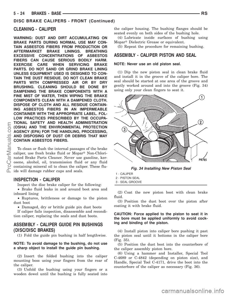
and install it in the groove of the caliper bore. The
seal should be started at one area of the groove and
gently worked around and into the groove (Fig. 34)
using only your clean fingers to seat it.
(2) Coat the new piston boot with clean brake
fluid.
(3) Position the dust boot over the piston after
coating it with brake fluid.
CAUTION: Force applied to the piston to seat it in
the bore must be applied uniformly to avoid cock-
ing and binding of the piston.
(4) Install piston into caliper bore pushing it past
the piston seal until it bottoms in the caliper bore
(Fig. 35).
(5) Position the dust boot into the counterbore of
the caliper assembly piston bore.
(6) Using a hammer and Installer, Special Tool
C-4689 or C-4842 (depending on piston size), and
Handle, Special Tool C-4171, drive the boot into the
counterbore of the caliper as necessary (Fig. 36).
Fig. 34 Installing New Piston Seal
1 - CALIPER
2 - PISTON SEAL
3 - SEAL GROOVE
5 - 24 BRAKES - BASERS
DISC BRAKE CALIPERS - FRONT (Continued)
ProCarManuals.com
Page 187 of 2321
CLEANING - CALIPER
WARNING: DUST AND DIRT ACCUMULATING ON
BRAKE PARTS DURING NORMAL USE MAY CON-
TAIN ASBESTOS FIBERS FROM PRODUCTION OR
AFTERMARKET BRAKE LININGS. BREATHING
EXCESSIVE CONCENTRATIONS OF ASBESTOS
FIBERS CAN CAUSE SERIOUS BODILY HARM.
EXERCISE CARE WHEN SERVICING BRAKE
PARTS. DO NOT SAND OR GRIND BRAKE LINING
UNLESS EQUIPMENT USED IS DESIGNED TO CON-
TAIN THE DUST RESIDUE. DO NOT CLEAN BRAKE
PARTS WITH COMPRESSED AIR OR BY DRY
BRUSHING. CLEANING SHOULD BE DONE BY
DAMPENING THE BRAKE COMPONENTS WITH A
FINE MIST OF WATER, THEN WIPING THE BRAKE
COMPONENTS CLEAN WITH A DAMPENED CLOTH.
DISPOSE OF CLOTH AND ALL RESIDUE CONTAIN-
ING ASBESTOS FIBERS IN AN IMPERMEABLE
CONTAINER WITH THE APPROPRIATE LABEL. FOL-
LOW PRACTICES PRESCRIBED BY THE OCCUPA-
TIONAL SAFETY AND HEALTH ADMINISTRATION
(OSHA) AND THE ENVIRONMENTAL PROTECTION
AGENCY (EPA) FOR THE HANDLING, PROCESSING,
AND DISPOSING OF DUST OR DEBRIS THAT MAY
CONTAIN ASBESTOS FIBERS.
To clean or flush the internal passages of the brake
caliper, use fresh brake fluid or MopartNon-Chlori-
nated Brake Parts Cleaner. Never use gasoline, ker-
osene, alcohol, oil, transmission fluid or any fluid
containing mineral oil to clean the caliper. These flu-
ids will damage rubber cups and seals.
INSPECTION - CALIPER
Inspect the disc brake caliper for the following:
²Brake fluid leaks in and around boot area and
inboard lining
²Ruptures, brittleness or damage to the piston
dust boot
²Damaged, dry or brittle guide pin dust boots
If caliper fails inspection, disassemble and recondi-
tion caliper, replacing the seals and dust boots.
ASSEMBLY - CALIPER PISTON AND SEAL
NOTE: Never use an old piston seal.
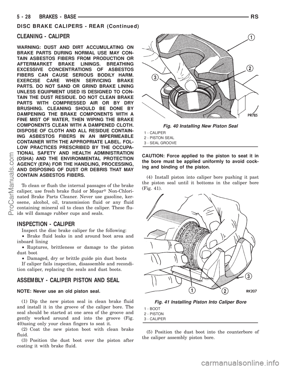
(1) Dip the new piston seal in clean brake fluid
and install it in the groove of the caliper bore. The
seal should be started at one area of the groove and
gently worked around and into the groove (Fig.
40)using only your clean fingers to seat it.
(2) Coat the new piston boot with clean brake
fluid.
(3) Position the dust boot over the piston after
coating it with brake fluid.CAUTION: Force applied to the piston to seat it in
the bore must be applied uniformly to avoid cock-
ing and binding of the piston.
(4) Install piston into caliper bore pushing it past
the piston seal until it bottoms in the caliper bore
(Fig. 41).
(5) Position the dust boot into the counterbore of
the caliper assembly piston bore.
Fig. 40 Installing New Piston Seal
1 - CALIPER
2 - PISTON SEAL
3 - SEAL GROOVE
Fig. 41 Installing Piston Into Caliper Bore
1 - BOOT
2 - PISTON
3 - CALIPER
5 - 28 BRAKES - BASERS
DISC BRAKE CALIPERS - REAR (Continued)
ProCarManuals.com
Page 191 of 2321
STANDARD PROCEDURE - BRAKE FLUID
LEVEL CHECKING
Check master cylinder reservoir fluid level a mini-
mum of twice annually.
Fluid reservoirs are marked with the words FULL
and ADD to indicate proper brake fluid fill level of
the master cylinder.
If necessary, add brake fluid to bring the level to
the bottom of the FULL mark on the side of the mas-
ter cylinder fluid reservoir.
Use only Mopartbrake fluid or equivalent from a
sealed container. Brake fluid must conform to DOT 3
specifications (DOT 4 or DOT 4+ are acceptable).
DO NOTuse brake fluid with a lower boiling
point, as brake failure could result during prolonged
hard braking.
Use only brake fluid that was stored in a tightly-
sealed container.
DO NOTuse petroleum-based fluid because seal
damage will result. Petroleum based fluids would be
items such as engine oil, transmission fluid, power
steering fluid etc.
SPECIFICATIONS
BRAKE FLUID
The brake fluid used in this vehicle must conform
to DOT 3 specifications (DOT 4 and DOT 4+ are
acceptable) and SAE J1703 standards. No other type
of brake fluid is recommended or approved for usage
in the vehicle brake system. Use only MopartBrake
Fluid or equivalent from a tightly sealed container.
CAUTION: Never use reclaimed brake fluid or fluid
from an container which has been left open. An
open container of brake fluid will absorb moisture
from the air and contaminate the fluid.
CAUTION: Never use any type of a petroleum-based
fluid in the brake hydraulic system. Use of such
type fluids will result in seal damage of the vehicle
brake hydraulic system causing a failure of the
vehicle brake system. Petroleum based fluids would
be items such as engine oil, transmission fluid,
power steering fluid, etc.
JUNCTION BLOCK
DESCRIPTION - NON-ABS JUNCTION BLOCK
A junction block is used on vehicles that are not
equipped with antilock brakes (ABS). The junction
block mounts in the same location as the integrated
control unit (ICU) does on vehicles equipped withABS. This allows for use of the same brake tube con-
figuration on all vehicles. The junction block is
located on the driver's side of the front suspension
cradle/crossmember below the master cylinder (Fig.
46).
It has six threaded ports to which the brake tubes
connect. Two are for the primary and secondary
brake tubes coming from the master cylinder. The
remaining four are for the chassis brake tubes going
to each brake assembly.
OPERATION - NON-ABS JUNCTION BLOCK
The junction block distributes the brake fluid com-
ing from the master cylinder primary and secondary
ports to the four chassis brake tubes leading to the
brakes at each wheel. Since the junction block
mounts in the same location as the ABS integrated
control unit (ICU), it allows for the common use of
brake tubes going to the brakes whether the vehicle
is equipped with or without ABS.
NOTE: Although the brake tubes coming from the
master cylinder to the junction block or ABS ICU
may appear to be the same, they are not. They are
unique to each brake system application.
REMOVAL - NON-ABS JUNCTION BLOCK
(1) Using a brake pedal depressor, move and lock
the brake pedal to a position past its first 1 inch of
travel. This will prevent brake fluid from draining
out of the master cylinder when the brake tubes are
removed from the junction block.
(2) Disconnect the battery negative cable.
(3) If the vehicle is equipped with speed control,
perform the following:
(a) Disconnect the battery positive cable.
(b) Remove the battery (Refer to 8 - ELECTRI-
CAL/BATTERY SYSTEM/BATTERY - REMOVAL).
(c) Disconnect the vacuum hose connector at the
tank built into the battery tray.
(d) Remove the screw securing the coolant filler
neck to the battery tray.
(e) Remove the battery tray (Refer to 8 - ELEC-
TRICAL/BATTERY SYSTEM/TRAY - REMOVAL).
(f) Remove the fasteners and move the speed
control servo off to the side, out of the way.
CAUTION: Before removing the brake tubes from
the junction block, the junction block and the brake
tubes must be thoroughly cleaned. This is required
to prevent contamination from entering the brake
hydraulic system.
5 - 32 BRAKES - BASERS
FLUID (Continued)
ProCarManuals.com
Page 239 of 2321
Use only brake fluid that was stored in a tightly-
sealed container.
DO NOTuse petroleum-based fluid because seal
damage will result. Petroleum based fluids would be
items such as engine oil, transmission fluid, power
steering fluid etc.
MASTER CYLINDER - RHD
DESCRIPTION
The master cylinder used on right hand drive
(RHD) vehicles functions similarly to that used on
left hand drive (LHD) vehicles. The RHD master cyl-
inder, as well as the RHD power brake booster, is
located in the same area, but lower in the engine
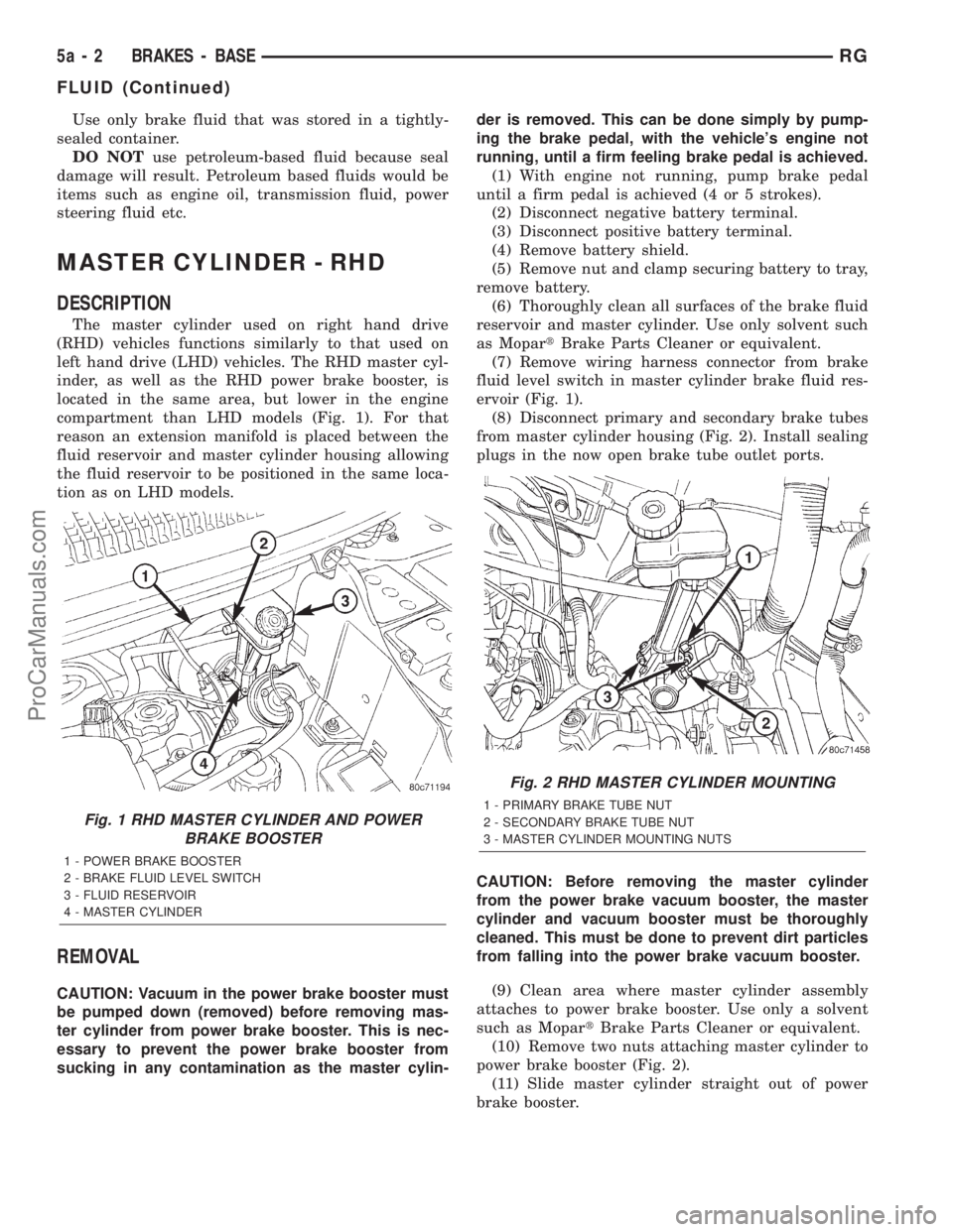
compartment than LHD models (Fig. 1). For that
reason an extension manifold is placed between the
fluid reservoir and master cylinder housing allowing
the fluid reservoir to be positioned in the same loca-
tion as on LHD models.
REMOVAL
CAUTION: Vacuum in the power brake booster must
be pumped down (removed) before removing mas-
ter cylinder from power brake booster. This is nec-
essary to prevent the power brake booster from
sucking in any contamination as the master cylin-der is removed. This can be done simply by pump-
ing the brake pedal, with the vehicle's engine not
running, until a firm feeling brake pedal is achieved.
(1) With engine not running, pump brake pedal
until a firm pedal is achieved (4 or 5 strokes).
(2) Disconnect negative battery terminal.
(3) Disconnect positive battery terminal.
(4) Remove battery shield.
(5) Remove nut and clamp securing battery to tray,
remove battery.
(6) Thoroughly clean all surfaces of the brake fluid
reservoir and master cylinder. Use only solvent such
as MopartBrake Parts Cleaner or equivalent.
(7) Remove wiring harness connector from brake
fluid level switch in master cylinder brake fluid res-
ervoir (Fig. 1).
(8) Disconnect primary and secondary brake tubes
from master cylinder housing (Fig. 2). Install sealing
plugs in the now open brake tube outlet ports.
CAUTION: Before removing the master cylinder
from the power brake vacuum booster, the master
cylinder and vacuum booster must be thoroughly
cleaned. This must be done to prevent dirt particles
from falling into the power brake vacuum booster.
(9) Clean area where master cylinder assembly
attaches to power brake booster. Use only a solvent
such as MopartBrake Parts Cleaner or equivalent.
(10) Remove two nuts attaching master cylinder to
power brake booster (Fig. 2).
(11) Slide master cylinder straight out of power
brake booster.
Fig. 1 RHD MASTER CYLINDER AND POWER
BRAKE BOOSTER
1 - POWER BRAKE BOOSTER
2 - BRAKE FLUID LEVEL SWITCH
3 - FLUID RESERVOIR
4 - MASTER CYLINDER
Fig. 2 RHD MASTER CYLINDER MOUNTING
1 - PRIMARY BRAKE TUBE NUT
2 - SECONDARY BRAKE TUBE NUT
3 - MASTER CYLINDER MOUNTING NUTS
5a - 2 BRAKES - BASERG
FLUID (Continued)
ProCarManuals.com
Page 304 of 2321
- 31TH/OIL PUMP - STANDARD PROCEDURE)
(Refer to 21 - TRANSMISSION/TRANSAXLE/AU-
TOMATIC - 41TE/OIL PUMP - STANDARD PRO-
CEDURE)
(b) If oil pump volume is within specification, a
possible restriction in the cooler lines or cooler has
occurred.
(c) If oil pump volume is not within specification,
possible internal transmission restrictions, compo-
nent wear or damage has occurred. (Refer to 21 -
TRANSMISSION/TRANSAXLE/AUTOMATIC -
31TH - DIAGNOSIS AND TESTING) (Refer to 21 -
TRANSMISSION/TRANSAXLE/AUTOMATIC -
41TE - DIAGNOSIS AND TESTING)
(d) If an oil cooler restriction is suspected, per-
form further inspections and flow meter testing by
isolating components (i.e. lines, coolers).
(e) After a restriction is isolated, perform cooler
flush procedure. (Refer to 7 - COOLING/TRANS-
MISSION - STANDARD PROCEDURE)
(f) Re-test cooler flow. If cooler flow does not
exceed minimum specification, replace compo-
nent(s) as necessary.
STANDARD PROCEDURE - FLUSHING
COOLERS AND TUBES
The recommended procedure for cooler flushing is
to use Tool 6906 Cooler Flusher.
WARNING:
WEAR PROTECTIVE EYEWEAR THAT MEETS THE
REQUIREMENTS OF OSHA AND ANSI Z87.1±1968.
WEAR STANDARD INDUSTRIAL RUBBER GLOVES.
KEEP LIGHTED CIGARETTES, SPARKS, FLAMES,
AND OTHER IGNITION SOURCES AWAY FROM THE
AREA TO PREVENT THE IGNITION OF COMBUSTI-
BLE LIQUIDS AND GASES. KEEP A CLASS (B) FIRE
EXTINGUISHER IN THE AREA WHERE THE
FLUSHER WILL BE USED.
KEEP THE AREA WELL VENTILATED.
DO NOT LET FLUSHING SOLVENT COME IN CON-
TACT WITH YOUR EYES OR SKIN: IF EYE CONTAM-
INATION OCCURS, FLUSH EYES WITH WATER FOR15 TO 20 SECONDS. REMOVE CONTAMINATED
CLOTHING AND WASH AFFECTED SKIN WITH
SOAP AND WATER. SEEK MEDICAL ATTENTION.
(1) Remove cover plate filler plug on Tool 6906.
Fill reservoir 1/2 to 3/4 full of fresh flushing solution.
Use MopartTransmission Cooler Flush (MS-552) or
equivalent solution conforming to MS-552. Flushing
solvents are petroleum based solutions generally
used to clean automatic transmission components.
DO NOTuse solvents containing acids, water, gaso-
line, or any other corrosive liquids.
(2) Reinstall filler plug on Tool 6906.
(3) Verify pump power switch is turned OFF. Con-
nect red alligator clip to positive (+) battery post.
Connect black (-) alligator clip to a good ground.
NOTE: When flushing transmission cooler and
lines, ALWAYS reverse flush.
(4) Connect the BLUE pressure line to the OUT-
LET (From) cooler line.
(5) Connect the CLEAR return line to the INLET
(To) cooler line
(6) Turn pump ON for two to three minutes to
flush cooler and lines.
(7) Turn pump OFF.
(8) Disconnect CLEAR suction line from reservoir
at cover plate. Disconnect CLEAR return line at
cover plate, and place it in a drain pan.
(9) Turn pump ON for 30 seconds to purge flush-
ing solution from cooler and lines. Turn pump OFF.
(10) Place CLEAR suction line into a one quart
container of MopartATF+4 (Automatic Transmission
FluidÐType 9602).
(11) Turn pump ON until all transmission fluid is
removed from the one quart container and lines. This
purges any residual cleaning solvent from the trans-
mission cooler and lines. Turn pump OFF.
(12) Disconnect alligator clips from battery. Recon-
nect flusher lines to cover plate, and remove flushing
adapters from cooler lines.
RSTRANSMISSION7-37
TRANSMISSION (Continued)
ProCarManuals.com
Page 305 of 2321
TRANS COOLER
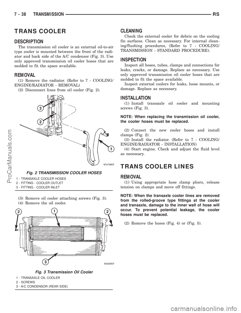
DESCRIPTION
The transmission oil cooler is an external oil-to-air
type cooler is mounted between the front of the radi-
ator and back side of the A/C condensor (Fig. 3). Use
only approved transmission oil cooler hoses that are
molded to fit the space available.
REMOVAL
(1) Remove the radiator. (Refer to 7 - COOLING/
ENGINE/RADIATOR - REMOVAL)
(2) Disconnect lines from oil cooler (Fig. 2).
(3) Remove oil cooler attaching screws (Fig. 3).
(4) Remove the oil cooler.
CLEANING
Check the external cooler for debris on the cooling
fin surfaces. Clean as necessary. For internal clean-
ing/flushing procedures, (Refer to 7 - COOLING/
TRANSMISSION - STANDARD PROCEDURE).
INSPECTION
Inspect all hoses, tubes, clamps and connections for
leaks, cracks, or damage. Replace as necessary. Use
only approved transmission oil cooler hoses that are
molded to fit the space available.
Inspect external coolers for leaks, loose mounts, or
damage. Replace as necessary.
INSTALLATION
(1) Install transaxle oil cooler and mounting
screws (Fig. 3).
NOTE: When replacing the transmission oil cooler,
the cooler hoses must be replaced.
(2) Connect the new cooler hoses and install
clamps (Fig. 2).
(3) Install the radiator. (Refer to 7 - COOLING/
ENGINE/RADIATOR - INSTALLATION)
(4) Start engine. Check and adjust the fluid level
as necessary.
TRANS COOLER LINES
REMOVAL
(1) Using appropriate hose clamp pliers, release
tension on clamps and move off fittings.
NOTE: When the transaxle cooler lines are removed
from the rolled-groove type fittings at the cooler
and transaxle, damage to the inner wall of hose will
occur. To prevent potential leakage, the cooler
hoses must be replaced.
(2) Remove the hoses (Fig. 4) or (Fig. 5).
Fig. 2 TRANSMISSION COOLER HOSES
1 - TRANSAXLE COOLER HOSES
2 - FITTING - COOLER OUTLET
3 - FITTING - COOLER INLET
Fig. 3 Transmission Oil Cooler
1 - TRANSAXLE OIL COOLER
2 - SCREWS
3 - A/C CONDENSOR (REAR SIDE)
7 - 38 TRANSMISSIONRS
ProCarManuals.com
Page 306 of 2321
INSTALLATION
NOTE: When the transaxle cooler lines are removed
from the rolled-groove type fittings at the cooler
and transaxle, damage to the inner wall of hose willoccur. To prevent potential leakage, the cooler
hoses must be replaced.
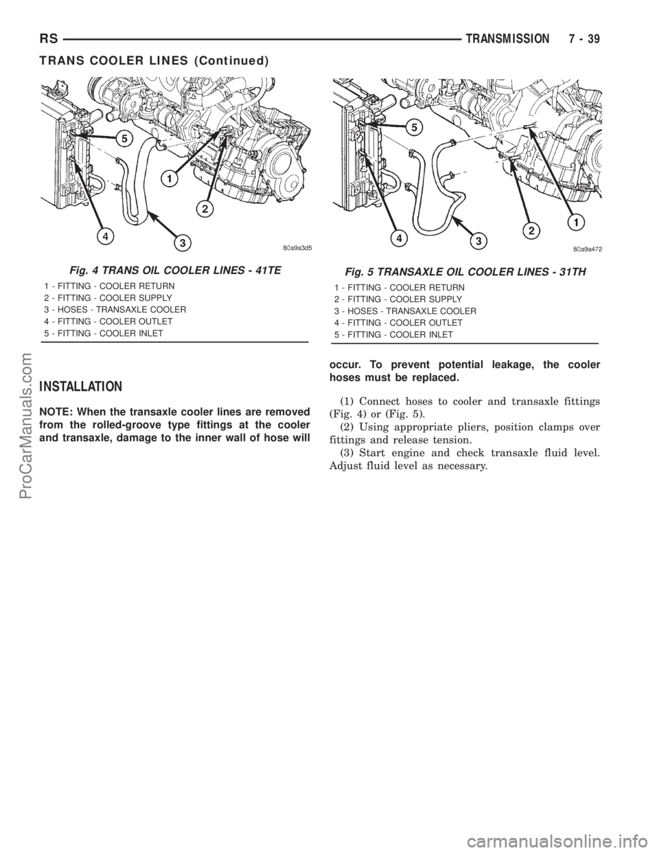
(1) Connect hoses to cooler and transaxle fittings
(Fig. 4) or (Fig. 5).
(2) Using appropriate pliers, position clamps over
fittings and release tension.
(3) Start engine and check transaxle fluid level.
Adjust fluid level as necessary.
Fig. 4 TRANS OIL COOLER LINES - 41TE
1 - FITTING - COOLER RETURN
2 - FITTING - COOLER SUPPLY
3 - HOSES - TRANSAXLE COOLER
4 - FITTING - COOLER OUTLET
5 - FITTING - COOLER INLET
Fig. 5 TRANSAXLE OIL COOLER LINES - 31TH
1 - FITTING - COOLER RETURN
2 - FITTING - COOLER SUPPLY
3 - HOSES - TRANSAXLE COOLER
4 - FITTING - COOLER OUTLET
5 - FITTING - COOLER INLET
RSTRANSMISSION7-39
TRANS COOLER LINES (Continued)
ProCarManuals.com
Page 371 of 2321

(M) Check Engine Lamp (MIL) will illuminate during engine operation if this Diagnostic Trouble Code was recorded.
(G) Generator Lamp Illuminated
GENERIC SCAN
TOOL CODEDRB SCAN TOOL DISPLAY DESCRIPTION OF DIAGNOSTIC TROUBLE CODE
P0461 Fuel Level Unit No Changeover
TimeNo level of fuel level sender detected.
P0462 Fuel Level Sending Unit Volts Too
LowFuel level sensor input below acceptable voltage.
P0463 Fuel Level Sending Unit Volts Too
HighFuel level sensor input above acceptable voltage.
P0500 (M) No Vehicle Speed Sensor Signal No vehicle speed sensor signal detected during road load
conditions.
P0505 (M) Idle Air Control Motor Circuits Replace
P0508 Idle Air Control Motor Circuit Low Idle Air Control Motor Circuit input below acceptable current
P0509 Idle Air Control Motor Circuit High Idle Air Control Motor Circuit input above acceptable current
P0522 Oil Pressure Sens Low Oil pressure sensor input below acceptable voltage.
P0523 Oil Pressure Sens High Oil pressure sensor input above acceptable voltage.
P0551 (M) Power Steering Switch Failure Incorrect input state detected for the power steering switch
circuit. PL: High pressure seen at high speed.
P0600 (M) PCM Failure SPI Communications No communication detected between co-processors in the
control module.
P0601 (M) Internal Controller Failure Internal control module fault condition (check sum) detected.
P0604 Internal Trans Controller Transmission control module RAM self test fault detected.
-Aisin transmission.
P0605 Internal Trans Controller Transmission control module ROM self test fault detected
-Aisin transmission.
P0622 (G) Generator Field Not Switching
ProperlyAn open or shorted condition detected in the generator field
control circuit.
P0645 A/C Clutch Relay Circuit An open or shorted condition detected in the A/C clutch relay
control circuit.
P0700 (M) EATX Controller DTC Present This SBEC III or JTEC DTC indicates that the EATX or Aisin
controller has an active fault and has illuminated the MIL via
a CCD (EATX) or SCI (Aisin) message. The specific fault
must be acquired from the EATX via CCD or from the Aisin
via ISO-9141.
P0703 (M) Brake Switch Stuck Pressed or
ReleasedIncorrect input state detected in the brake switch circuit.
(Changed from P1595).
P0711 Trans Temp Sensor, No Temp Rise
After StartRelationship between the transmission temperature and
overdrive operation and/or TCC operation indicates a failure
of the Transmission Temperature Sensor. OBD II Rationality.
P0712 Trans Temp Sensor Voltage Too Low Transmission fluid temperature sensor input below
acceptable voltage.
P0713 Trans Temp Sensor Voltage Too
HighTransmission fluid temperature sensor input above
acceptable voltage.
P0720 Low Output SPD Sensor RPM,
Above 15 MPHThe relationship between the Output Shaft Speed Sensor
and vehicle speed is not within acceptable limits.
8E - 14 ELECTRONIC CONTROL MODULESRS
POWERTRAIN CONTROL MODULE (Continued)
ProCarManuals.com