2001 DODGE TOWN AND COUNTRY transmission fluid
[x] Cancel search: transmission fluidPage 43 of 2321
MopartATF+4 (Automatic Transmission Fluid-
Type 9602) when new is red in color. The ATF is dyed
red so it can be identified from other fluids used in
the vehicle such as engine oil or antifreeze. The red
color is not permanent and is not an indicator of fluid
condition. As the vehicle is driven, the ATF will begin
to look darker in color and may eventually become
brown.This is normal.A dark brown/black fluid
accompanied with a burnt odor and/or deterioration
in shift quality may indicate fluid deterioration or
transmission component failure.
FLUID ADDITIVES
DaimlerChrysler strongly recommends against the
addition of any fluids to the transmission, other than
those automatic transmission fluids listed above.
Exceptions to this policy are the use of special dyes
to aid in detecting fluid leaks.
Various ªspecialº additives and supplements exist
that claim to improve shift feel and/or quality. These
additives and others also claim to improve converter
clutch operation and inhibit overheating, oxidation,
varnish, and sludge. These claims have not been sup-
ported to the satisfaction of DaimlerChrysler and these
additivesmust not be used.
The use of transmission
ªsealersº should also be avoided, since they may
adversely affect the integrity of transmission seals.
DESCRIPTION - FUEL REQUIREMENTS -
DIESEL ENGINE
WARNING: DO NOT USE ALCOHOL OR GASOLINE
AS A FUEL BLENDING AGENT. THEY CAN BE
UNSTABLE UNDER CERTAIN CONDITIONS AND
HAZARDOUS OR EXPLOSIVE WHEN MIXED WITH
DIESEL FUEL.
Use good quality diesel fuel from a reputable sup-
plier. For most year-round service, number 2 diesel
fuel meeting ASTM specification D-975 will provide
good performance. If the vehicle is exposed to
extreme cold (below -18ÉC/0ÉF) or is required to oper-
ate at colder than normal conditions for prolonged
periods, use climatize No. 2 diesel fuel or dilute the
No. 2 diesel fuel with 50% No. 1 diesel fuel. This will
provide better protection from fuel gelling or wax
plugging of the fuel filters.
Diesel fuel is seldom completely free of water. To
prevent fuel system trouble, including fuel line freez-
ing in winter, drain the accumulated water from the
fuel/water separator using the fuel/water separator
drain provided. If you buy good quality fuel and follow
the cold weather advice above, fuel conditioners should
not be required in your vehicle. If available in your
area, a high cetane ªpremiumº diesel fuel may offer
improved cold starting and warm up performance.
DESCRIPTION - DIESEL ENGINE OIL
API SERVICE GRADE CERTIFIED
WARNING: NEW OR USED ENGINE OIL CAN BE
IRRITATING TO THE SKIN. AVOID PROLONGED OR
REPEATED SKIN CONTACT WITH ENGINE OIL.
CONTAMINANTS IN USED ENGINE OIL, CAUSED BY
INTERNAL COMBUSTION, CAN BE HAZARDOUS TO
YOUR HEALTH. THOROUGHLY WASH EXPOSED
SKIN WITH SOAP AND WATER. DO NOT WASH
SKIN WITH GASOLINE, DIESEL FUEL, THINNER, OR
SOLVENTS, HEALTH PROBLEMS CAN RESULT. DO
NOT POLLUTE, DISPOSE OF USED ENGINE OIL
PROPERLY. CONTACT YOUR DEALER OR GOVERN-
MENT AGENCY FOR LOCATION OF COLLECTION
CENTER IN YOUR AREA.
Standard engine oil identification notations have
been adopted to aid in the proper selection of engine
oil. The identifying notations are located on the label
of engine oil plastic bottles and the top of engine oil
cans.
In diesel engines, use an engine oil that conforms
to API Service Grade CF-4 or CG-4/SH (Fig. 5).
MOPARtprovides an engine oil that conforms to this
particular grade.
SAE VISCOSITY
An SAE viscosity grade is used to specify the vis-
cosity of engine oil. SAE 15W±40 specifies a multiple
viscosity engine oil.
When choosing an engine oil, consider the range of
temperatures the vehicle will be operated in before the
next oil change. Select an engine oil that is best suited
to your area's particular ambient temperature range
and variation. For diesel engines, refer to (Fig. 6).
Fig. 5 API Service Grade Certification LabelÐDiesel
Engine Oil
0a - 4 LUBRICATION & MAINTENANCE - RG - 2.5 L TURBO DIESELRG
FLUID TYPES (Continued)
ProCarManuals.com
Page 47 of 2321
JUMP STARTING
STANDARD PROCEDURE - JUMP STARTING
(1) Raise hood on disabled vehicle and visually
inspect engine compartment for:
²Battery cable clamp condition, clean if necessary.
²Frozen battery.
²Yellow or bright color test indicator, if equipped.
²Low battery fluid level.
²Generator drive belt condition and tension.
²Fuel fumes or leakage, correct if necessary.
CAUTION: If the cause of starting problem on dis-
abled vehicle is severe, damage to booster vehicle
charging system can result.
(2) When using another vehicle as a booster
source, park the booster vehicle within cable reach.
Turn off all accessories, set the parking brake, place
the automatic transmission in PARK or the manual
transmission in NEUTRAL and turn the ignition
OFF.
(3)
On disabled vehicle, place gear selector in park
or neutral and set park brake. Turn off all accessories.
(4) Connect jumper cables to booster battery. RED
clamp to positive terminal (+). BLACK clamp to neg-
ative terminal (-). DO NOT allow clamps at opposite
end of cables to touch, electrical arc will result.
Review all warnings in this procedure.
(5) On disabled vehicle, connect RED jumper cable
clamp to positive (+) terminal. Connect BLACK
jumper cable clamp to engine ground as close to the
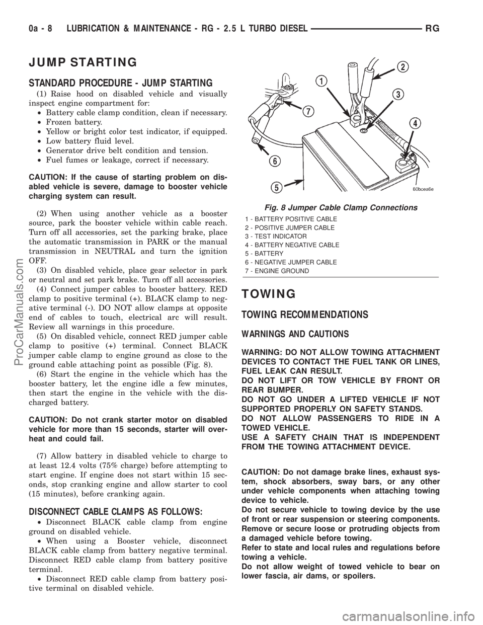
ground cable attaching point as possible (Fig. 8).
(6) Start the engine in the vehicle which has the
booster battery, let the engine idle a few minutes,
then start the engine in the vehicle with the dis-
charged battery.
CAUTION: Do not crank starter motor on disabled
vehicle for more than 15 seconds, starter will over-
heat and could fail.
(7) Allow battery in disabled vehicle to charge to
at least 12.4 volts (75% charge) before attempting to
start engine. If engine does not start within 15 sec-
onds, stop cranking engine and allow starter to cool
(15 minutes), before cranking again.
DISCONNECT CABLE CLAMPS AS FOLLOWS:
²Disconnect BLACK cable clamp from engine
ground on disabled vehicle.
²When using a Booster vehicle, disconnect
BLACK cable clamp from battery negative terminal.
Disconnect RED cable clamp from battery positive
terminal.
²Disconnect RED cable clamp from battery posi-
tive terminal on disabled vehicle.
TOWING
TOWING RECOMMENDATIONS
WARNINGS AND CAUTIONS
WARNING: DO NOT ALLOW TOWING ATTACHMENT
DEVICES TO CONTACT THE FUEL TANK OR LINES,
FUEL LEAK CAN RESULT.
DO NOT LIFT OR TOW VEHICLE BY FRONT OR
REAR BUMPER.
DO NOT GO UNDER A LIFTED VEHICLE IF NOT
SUPPORTED PROPERLY ON SAFETY STANDS.
DO NOT ALLOW PASSENGERS TO RIDE IN A
TOWED VEHICLE.
USE A SAFETY CHAIN THAT IS INDEPENDENT
FROM THE TOWING ATTACHMENT DEVICE.
CAUTION: Do not damage brake lines, exhaust sys-
tem, shock absorbers, sway bars, or any other
under vehicle components when attaching towing
device to vehicle.
Do not secure vehicle to towing device by the use
of front or rear suspension or steering components.
Remove or secure loose or protruding objects from
a damaged vehicle before towing.
Refer to state and local rules and regulations before
towing a vehicle.
Do not allow weight of towed vehicle to bear on
lower fascia, air dams, or spoilers.
Fig. 8 Jumper Cable Clamp Connections
1 - BATTERY POSITIVE CABLE
2 - POSITIVE JUMPER CABLE
3 - TEST INDICATOR
4 - BATTERY NEGATIVE CABLE
5 - BATTERY
6 - NEGATIVE JUMPER CABLE
7 - ENGINE GROUND
0a - 8 LUBRICATION & MAINTENANCE - RG - 2.5 L TURBO DIESELRG
ProCarManuals.com
Page 115 of 2321
(7) Install steering knuckle in clevis bracket of
strut damper assembly. Install the strut damper to
steering knuckle attaching bolts. Tighten both bolts
to a torque of 81 N´m (60 ft. lbs.) plus an additional
1/4 turn.
(8) Install tie rod end into steering knuckle. Start
attaching nut onto stud of tie rod end. While holding
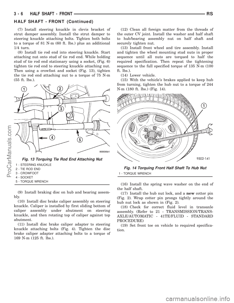
stud of tie rod end stationary using a socket, (Fig. 6)
tighten tie rod end to steering knuckle attaching nut.
Then using a crowfoot and socket (Fig. 13), tighten
the tie rod end attaching nut to a torque of 75 N´m
(55 ft. lbs.).
(9) Install braking disc on hub and bearing assem-
bly.
(10) Install disc brake caliper assembly on steering
knuckle. Caliper is installed by first sliding bottom of
caliper assembly under abutment on steering
knuckle, and then rotating top of caliper against top
abutment.
(11) Install disc brake caliper adapter to steering
knuckle attaching bolts (Fig. 4). Tighten the disc
brake caliper adapter attaching bolts to a torque of
169 N´m (125 ft. lbs.).(12) Clean all foreign matter from the threads of
the outer CV joint. Install the washer and half shaft
to hub/bearing assembly nut on half shaft and
securely tighten nut.
(13) Install front wheel and tire assembly. Install
and tighten the wheel mounting stud nuts in proper
sequence until all nuts are torqued to half the
required specification. Then repeat the tightening
sequence to the full specified torque of 135 N´m (100
ft. lbs.).
(14) Lower vehicle.
(15) With the vehicle's brakes applied to keep hub
from turning, tighten the hub nut to a torque of 244
N´m (180 ft. lbs.) (Fig. 14).
(16) Install the spring wave washer on the end of
the half shaft.
(17) Install the hub nut lock, and anewcotter pin
(Fig. 2). Wrap cotter pin prongs tightly around the
hub nut lock as shown in (Fig. 2).
(18) Check for correct fluid level in transaxle
assembly. (Refer to 21 - TRANSMISSION/TRANS-
AXLE/AUTOMATIC - 41TE/FLUID - STANDARD
PROCEDURE)
(19) Set front toe on vehicle to required specifica-
tion.
Fig. 13 Torquing Tie Rod End Attaching Nut
1 - STEERING KNUCKLE
2 - TIE ROD END
3 - CROWFOOT
4 - SOCKET
5 - TORQUE WRENCHFig. 14 Torquing Front Half Shaft To Hub Nut
1 - TORQUE WRENCH
3 - 6 HALF SHAFT - FRONTRS
HALF SHAFT - FRONT (Continued)
ProCarManuals.com
Page 135 of 2321
REAR DRIVELINE MODULE
TABLE OF CONTENTS
page page
REAR DRIVELINE MODULE
DESCRIPTION...........................26
OPERATION.............................26
DIAGNOSIS AND TESTING.................27
REAR DRIVELINE MODULE NOISE.........27
REAR DRIVELINE MODULE OPERATION....29
REMOVAL..............................29
DISASSEMBLY...........................30
ASSEMBLY.............................32
INSTALLATION...........................36
SPECIFICATIONS........................37
SPECIAL TOOLS.........................37
BI-DIRECTIONAL OVERRUNNING CLUTCH
DESCRIPTION...........................37
OPERATION.............................38
DIFFERENTIAL ASSEMBLY
DESCRIPTION...........................43
OPERATION.............................43FLUID - DIFFERENTIAL ASSEMBLY
STANDARD PROCEDURE..................44
DIFFERENTIAL ASSEMBLY FLUID CHANGE . . 44
FLUID
STANDARD PROCEDURE..................44
OVERRUNNING CLUTCH HOUSING FLUID
CHANGE..............................44
VISCOUS COUPLER
DESCRIPTION...........................45
OPERATION.............................45
TORQUE ARM
REMOVAL..............................47
INSTALLATION...........................47
INPUT FLANGE SEAL
REMOVAL..............................47
INSTALLATION...........................47
OUTPUT FLANGE SEAL
REMOVAL..............................49
INSTALLATION...........................50
REAR DRIVELINE MODULE
DESCRIPTION
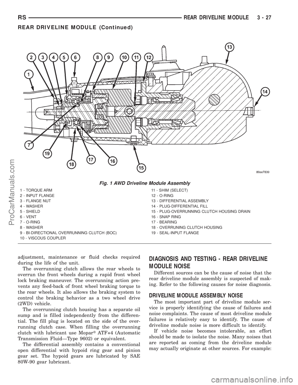
The rear driveline module assembly (Fig. 1) con-
sists of four main components:
²Bi-Directional Overrunning Clutch (BOC)
²Viscous Coupling
²Differential Assembly
²Torque Arm
The viscous coupling and bi-directional overrun-
ning clutch are contained within an overrunning
clutch housing, which fastens to the differential
assembly. The overrunning clutch housing and differ-
ential assembly have unique fluid sumps, each
requiring their own type and capacity of fluid. The
overrunning clutch housing requires MopartATF+4
(Automatic Transmission FluidÐType 9602) or equiv-
alent. The differential assembly requires
Driveline module service is limited to the following
components:
²Differential Assembly (serviced only as assem-
bly)
²Viscous Coupling
²Bi-Directional Overrunning Clutch (BOC)
²Overrunning Clutch Housing
²Seals (Input Flange, Output Flange, Overrun-
ning Clutch Housing O-rings)
²Input Flange/Shield²Torque Arm
²Vents
²FastenersOPERATION
The primary benefits of All Wheel Drive are:
²Superior straight line acceleration, and corner-
ing on all surfaces
²Better traction and handling under adverse con-
ditions, resulting in improved hill climbing ability
and safer driving.
The heart of the system is an inter-axle viscous
coupling. The vehicle retains predominantly front-
wheel drive characteristics, but the All Wheel Drive
capability takes effect when the front wheels start to
slip. Under normal level road, straight line driving,
100% of the torque is allocated to the front wheels.
The viscous coupling controls and distributes torque/
power to the rear wheels. The viscous coupling trans-
mits torque to the rear wheels in proportion of the
amount of the slippage at the front wheels. Thais
variable torque distribution is automatic with no
driver inputs required. The coupling is similar to a
multi-plate clutch. It consists of a series of closely
spaced discs, which are alternately connected to the
front and rear drive units. The unit is totally sealed
and partially filled with silicone fluid. There is no
3 - 26 REAR DRIVELINE MODULERS
ProCarManuals.com
Page 136 of 2321
adjustment, maintenance or fluid checks required
during the life of the unit.
The overrunning clutch allows the rear wheels to
overrun the front wheels during a rapid front wheel
lock braking maneuver. The overrunning action pre-
vents any feed-back of front wheel braking torque to
the rear wheels. It also allows the braking system to
control the braking behavior as a two wheel drive
(2WD) vehicle.
The overrunning clutch housing has a separate oil
sump and is filled independently from the differen-
tial. The fill plug is located on the side of the over-
running clutch case. When filling the overrunning
clutch with lubricant use MopartATF+4 (Automatic
Transmission FluidÐType 9602) or equivalent.
The differential assembly contains a conventional
open differential with hypoid ring gear and pinion
gear set. The hypoid gears are lubricated by SAE
80W-90 gear lubricant.DIAGNOSIS AND TESTING - REAR DRIVELINE
MODULE NOISE
Different sources can be the cause of noise that the
rear driveline module assembly is suspected of mak-
ing. Refer to the following causes for noise diagnosis.
DRIVELINE MODULE ASSEMBLY NOISE
The most important part of driveline module ser-
vice is properly identifying the cause of failures and
noise complaints. The cause of most driveline module
failures is relatively easy to identify. The cause of
driveline module noise is more difficult to identify.
If vehicle noise becomes intolerable, an effort
should be made to isolate the noise. Many noises that
are reported as coming from the driveline module
may actually originate at other sources. For example:
Fig. 1 AWD Driveline Module Assembly
1 - TORQUE ARM
2 - INPUT FLANGE
3 - FLANGE NUT
4 - WASHER
5 - SHIELD
6 - VENT
7 - O-RING
8 - WASHER
9 - BI-DIRECTIONAL OVERRUNNING CLUTCH (BOC)
10 - VISCOUS COUPLER11 - SHIM (SELECT)
12 - O-RING
13 - DIFFERENTIAL ASSEMBLY
14 - PLUG-DIFFERENTIAL FILL
15 - PLUG-OVERRUNNING CLUTCH HOUSING DRAIN
16 - SNAP RING
17 - BEARING
18 - OVERRUNING CLUTCH HOUSING
19 - SEAL-INPUT FLANGE
RSREAR DRIVELINE MODULE3-27
REAR DRIVELINE MODULE (Continued)
ProCarManuals.com
Page 138 of 2321
DIAGNOSIS AND TESTING - REAR DRIVELINE
MODULE OPERATION
Driveline module operation requires relatively
straight-forward diagnosis. Refer to the following
chart:
DRIVELINE MODULE DIAGNOSIS CHART
CONDITION POSSIBLE CAUSES CORRECTION
Rear wheels not
overrunning1) Bi-directional overrunning clutch
failure1) Replace overrunning clutch
components as required
No AWD in forward or
reverse directions, propeller
shaft turning1) Bi-directional overrunning clutch
failure1) Replace overrunning clutch
components as required
2) Viscous coupling failure 2) Replace viscous coupling
3) Rear differential failure 3) Replace the rear differential
assembly
No AWD in forward or
reverse directions, propeller
shaft not turning1) Power transfer unit failure. 1) Replace power transfer unit
components as necessary
Vibration at all speeds,
continuous torque transfer1) Mis-matched tires, worn tires on
front axle.1) Replace worn or incorrect
(mis-matched) tires with same
make and size
REMOVAL
(1) Raise vehicle on hoist.
(2) Drain fluid from overrunning clutch housing
and/or differential assembly if necessary.
(3) Remove propeller shaft. (Refer to 3 - DIFFER-
ENTIAL & DRIVELINE/PROPELLER SHAFT -
REMOVAL)
(4) Disconnect left and right rear halfshafts from
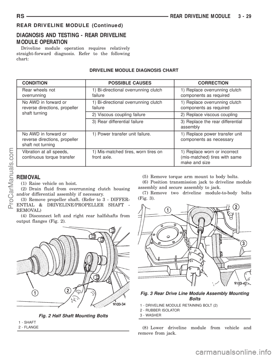
output flanges (Fig. 2).(5) Remove torque arm mount to body bolts.
(6) Position transmission jack to driveline module
assembly and secure assembly to jack.
(7) Remove two driveline module-to-body bolts
(Fig. 3).
(8) Lower driveline module from vehicle and
remove from jack.
Fig. 2 Half Shaft Mounting Bolts
1 - SHAFT
2 - FLANGE
Fig. 3 Rear Drive Line Module Assembly Mounting
Bolts
1 - DRIVELINE MODULE RETAINING BOLT (2)
2 - RUBBER ISOLATOR
3 - WASHER
RSREAR DRIVELINE MODULE3-29
REAR DRIVELINE MODULE (Continued)
ProCarManuals.com
Page 154 of 2321

(3) Remove overrunning clutch housing drain plug
and drain fluid (Fig. 43).
(4) Install the drain plug and torque to 30 N´m (22
ft. lbs.).
(5) Re-position the drain pan under the overrun-
ning clutch housing fill plug.
(6) Remove fill plug (Fig. 44).
(7) Using a suction gun (Fig. 45), add 0.58 L (1.22
pts.) of MopartATF+4 (Automatic Transmission Flu-
idÐType 9602).
(8)
Install fill plug and torque to 30 N´m (22 ft. lbs.).
VISCOUS COUPLER
DESCRIPTION
The heart of the all-wheel drive system is the inter-
axle viscous coupling and bi-directional overrunning
clutch. Under normal driving the vehicle retains pre-
dominantly front wheel drive characteristics. The all-
wheel drive takes effect when the front wheels start to
slip. Under normal level road, straight line driving,
100% of the torque is allocated to the front wheels.
The viscous coupler allows more torque to the rear
wheels in accordance with the amount of slippage at
the front wheels. The variable torque distribution is
automatic with no driver inputs required.
OPERATION
The viscous coupler (Fig. 46) is a housing nearly
filled with a high viscosity silicone liquid and thin
metal plates alternately splined to an inner and
outer drum. The viscous coupler provides torque in
the following modes:
²Shear mode (normal operation)
²Hump mode (locked mode)
The inner plates are slotted around the radius and
the outer plates have holes in them. In the shear
mode (normal operation), the plates are evenly
spaced and the torque is created by the shearing of
the plates through the fluid and 90-100% of the
torque is applied to the rear axle. During the shear
mode, a fluid flow pattern is created from this design
(holes and slots). This fluid flow causes high pressure
on each side of each pair of plates and low pressure
between each pair of plates.
Fig. 43 Overrunning Clutch Case Drain Plug
1 - OVERRUNNING CLUTCH HOUSING DRAIN PLUG
Fig. 44 Overrunning Clutch Housing Fill Plug
1 - OVERRUNNING CLUTCH HOUSING FILL PLUG
2 - FUEL TANK
Fig. 45 Filling Overrunning Clutch Case
1 - OVERRUNNING CLUTCH HOUSING FILL HOLE
2 - SUCTION GUN
RSREAR DRIVELINE MODULE3-45
FLUID (Continued)
ProCarManuals.com
Page 163 of 2321

RED BRAKE WARNING INDICATOR LAMP
CONDITION POSSIBLE CAUSES CORRECTION
RED BRAKE WARNING
LAMP ON1. Parking brake lever not fully
released.1. Release parking brake lever.
2. Parking brake warning lamp
switch on parking brake lever.2. Inspect and replace switch as necessary.
3. Brake fluid level low in reservoir. 3. Fill reservoir. Check entire system for
leaks. Repair or replace as required.
4. Brake fluid level switch. 4. Disconnect switch wiring connector. If
lamp goes out, replace switch.
5. Mechanical instrument cluster
(MIC) problem.5. Refer to appropriate Diagnostic
information.
6. Amber ABS Warning Indicator
Lamp also illuminated.6. Refer to appropriate Diagnostic
information.
BRAKE NOISE
CONDITION POSSIBLE CAUSES CORRECTION
CLICK OR SQUAWK ON
PEDAL APPLICATION1. Brake lamp switch. 1. Replace switch.
2. Brake Transmission Shift Interlock
Linkage.2. Lubricate BTSI linkage.
3. Pedal pivot bushings 3. Lubricate pivot bushings. Replace if
necessary.
DISC BRAKE CHIRP 1. Excessive brake rotor runout. 1. Follow brake rotor diagnosis and testing.
Correct as necessary.
2. Lack of lubricant on brake caliper
slides.2. Lubricate brake caliper slides.
3. Caliper/shoes not fully seated. 3. Reseat caliper/shoes.
DISC BRAKE RATTLE OR
CLUNK1. Broken or missing anti-rattle
spring clips on shoes.1. Replace brake shoes.
2. Caliper guide pins/bolts loose. 2. Tighten guide pins/bolts.
DISC BRAKE SQUEAK AT
LOW SPEED (WHILE
APPLYING LIGHT BRAKE
PEDAL EFFORT)1. Brake shoe linings. 1. Replace brake shoes.
DRUM BRAKE CHIRP 1. Lack of lubricant on brake shoe
support plate where shoes ride.1. Lubricate shoe contact areas on brake
shoe support plates.
DRUM BRAKE CLUNK 1. Drum(s) have threaded machined
braking surface.1. Reface or replace drake drums as
necessary.
DRUM BRAKE HOWL OR
MOAN1. Lack of lubricant on brake shoe
support plate where shoes ride and
at the anchor.1. Lubricate shoe contact areas on brake
shoe support plates and at the anchor.
2. Rear brake shoes. 2. Replace rear brake shoes.
DRUM BRAKE SCRAPING
OR WHIRRING1. ABS wheel speed sensor or tone
wheel.1. Inspect, correct or replace faulty
component(s).
5 - 4 BRAKES - BASERS
BRAKES - BASE (Continued)
ProCarManuals.com