2001 DODGE TOWN AND COUNTRY seats
[x] Cancel search: seatsPage 570 of 2321
DIAGNOSIS AND TESTING - POWER SEAT
RECLINER
Following are tests that will help to diagnose the
hard wired components and circuits of the power seat
system. However, if the vehicle is also equipped with
the optional memory system, these tests may not
prove conclusive in the diagnosis of the driver side
power seat. In order to obtain conclusive testing of
the driver side power seat with the memory system
option, the Programmable Communications Interface
(PCI) data bus network and all of the electronic mod-
ules that provide inputs to, or receive outputs from
the memory system components must be checked.The most reliable, efficient, and accurate means to
diagnose the driver side power seat with the memory
system option requires the use of a DRBtscan tool
and the proper Diagnostic Procedures manual. The
DRBtscan tool can provide confirmation that the
PCI data bus is functional, that all of the electronic
modules are sending and receiving the proper mes-
sages on the PCI data bus, and that the memory sys-
tem is receiving the proper hard wired inputs and
relaying the proper hard wired outputs to perform its
driver side power seat functions.
Actuate the power seat recliner switch to move the
power seat recliner adjuster in each direction. The
power seat recliner adjuster should move in both
directions. If the power seat recliner adjuster fails to
operate in only one direction, move the adjuster a
short distance in the opposite direction and test
again to be certain that the adjuster is not at its
travel limit. If the power seat recliner adjuster still
fails to operate in only one direction, refer toPower
Seat Switchin the Diagnosis and Testing section of
this group. If the power recliner adjuster fails to
operate in either direction, perform the following
tests. For complete circuit diagrams, refer toPower
Seatin Wiring Diagrams.
(1) Check the power seat circuit breaker under the
seat. If OK, go to Step 2. If not OK, replace the
faulty power seat circuit breaker.
(2) Check for battery voltage at the power seat cir-
cuit breaker under the seat. If OK, go to Step 3. If
not OK, repair the open fused B(+) circuit to the fuse
in the Intelligent Power Module as required.
(3) Remove the outboard seat cushion side shield
from the seat. Disconnect the seat wire harness con-
nector from the power seat switch connector recepta-
cle. Check for battery voltage at the fused B(+)
circuit cavity of the power seat wire harness connec-
tor for the power seat switch. If OK, go to Step 4. If
not OK, repair the open fused B(+) circuit to the
power seat circuit breaker under the seat as
required.
(4) Check for continuity between the ground cir-
cuit cavity of the power seat wire harness connector
for the power seat switch and a good ground. There
should be continuity. If OK, go to Step 5. If not OK,
repair the open ground circuit to ground as required.
(5) Test the power seat switch. Refer toPower
Seat Switchin the Diagnosis and Testing section of
this group. If the switch tests OK, test the circuits of
the power seat wire harness between the power seat
recliner adjuster motor and the power seat switch for
shorts or opens. If the circuits check OK, replace the
faulty power seat recliner unit. If the circuits are not
OK, repair the power seat wire harness as required.
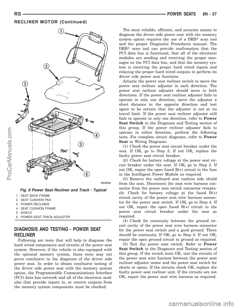
Fig. 8 Power Seat Recliner and Track - Typical
1 - SEAT BACK FRAME
2 - SEAT CUSHION PAD
3 - POWER RECLINER
4 - SEAT CUSHION FRAME
5 - SHIELD
6 - POWER SEAT TRACK ADJUSTER
RSPOWER SEATS8N-57
RECLINER MOTOR (Continued)
ProCarManuals.com
Page 571 of 2321
POWER SEAT TRACK
DESCRIPTION
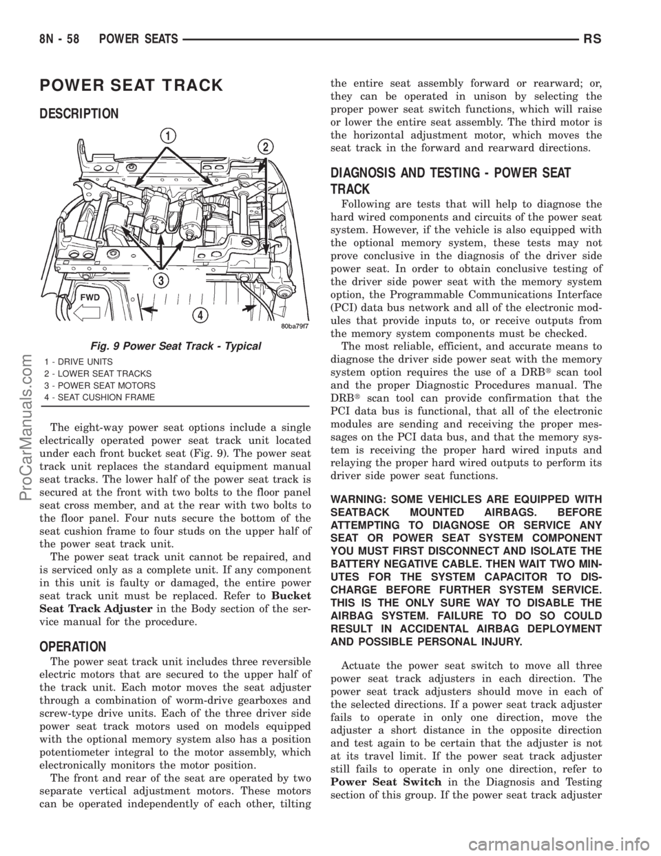
The eight-way power seat options include a single
electrically operated power seat track unit located
under each front bucket seat (Fig. 9). The power seat
track unit replaces the standard equipment manual
seat tracks. The lower half of the power seat track is
secured at the front with two bolts to the floor panel
seat cross member, and at the rear with two bolts to
the floor panel. Four nuts secure the bottom of the
seat cushion frame to four studs on the upper half of
the power seat track unit.
The power seat track unit cannot be repaired, and
is serviced only as a complete unit. If any component
in this unit is faulty or damaged, the entire power
seat track unit must be replaced. Refer toBucket
Seat Track Adjusterin the Body section of the ser-
vice manual for the procedure.
OPERATION
The power seat track unit includes three reversible
electric motors that are secured to the upper half of
the track unit. Each motor moves the seat adjuster
through a combination of worm-drive gearboxes and
screw-type drive units. Each of the three driver side
power seat track motors used on models equipped
with the optional memory system also has a position
potentiometer integral to the motor assembly, which
electronically monitors the motor position.
The front and rear of the seat are operated by two
separate vertical adjustment motors. These motors
can be operated independently of each other, tiltingthe entire seat assembly forward or rearward; or,
they can be operated in unison by selecting the
proper power seat switch functions, which will raise
or lower the entire seat assembly. The third motor is
the horizontal adjustment motor, which moves the
seat track in the forward and rearward directions.
DIAGNOSIS AND TESTING - POWER SEAT
TRACK
Following are tests that will help to diagnose the
hard wired components and circuits of the power seat
system. However, if the vehicle is also equipped with
the optional memory system, these tests may not
prove conclusive in the diagnosis of the driver side
power seat. In order to obtain conclusive testing of
the driver side power seat with the memory system
option, the Programmable Communications Interface
(PCI) data bus network and all of the electronic mod-
ules that provide inputs to, or receive outputs from
the memory system components must be checked.
The most reliable, efficient, and accurate means to
diagnose the driver side power seat with the memory
system option requires the use of a DRBtscan tool
and the proper Diagnostic Procedures manual. The
DRBtscan tool can provide confirmation that the
PCI data bus is functional, that all of the electronic
modules are sending and receiving the proper mes-
sages on the PCI data bus, and that the memory sys-
tem is receiving the proper hard wired inputs and
relaying the proper hard wired outputs to perform its
driver side power seat functions.
WARNING: SOME VEHICLES ARE EQUIPPED WITH
SEATBACK MOUNTED AIRBAGS. BEFORE
ATTEMPTING TO DIAGNOSE OR SERVICE ANY
SEAT OR POWER SEAT SYSTEM COMPONENT
YOU MUST FIRST DISCONNECT AND ISOLATE THE
BATTERY NEGATIVE CABLE. THEN WAIT TWO MIN-
UTES FOR THE SYSTEM CAPACITOR TO DIS-
CHARGE BEFORE FURTHER SYSTEM SERVICE.
THIS IS THE ONLY SURE WAY TO DISABLE THE
AIRBAG SYSTEM. FAILURE TO DO SO COULD
RESULT IN ACCIDENTAL AIRBAG DEPLOYMENT
AND POSSIBLE PERSONAL INJURY.
Actuate the power seat switch to move all three
power seat track adjusters in each direction. The
power seat track adjusters should move in each of
the selected directions. If a power seat track adjuster
fails to operate in only one direction, move the
adjuster a short distance in the opposite direction
and test again to be certain that the adjuster is not
at its travel limit. If the power seat track adjuster
still fails to operate in only one direction, refer to
Power Seat Switchin the Diagnosis and Testing
section of this group. If the power seat track adjuster
Fig. 9 Power Seat Track - Typical
1 - DRIVE UNITS
2 - LOWER SEAT TRACKS
3 - POWER SEAT MOTORS
4 - SEAT CUSHION FRAME
8N - 58 POWER SEATSRS
ProCarManuals.com
Page 572 of 2321
fails to operate in more than one direction, perform
the following tests. For complete circuit diagrams,
refer toPower Seatin Wiring Diagrams.
(1) Check the power seat circuit breaker under the
seat. If OK, go to Step 2. If not OK, replace the
faulty power seat circuit breaker.
(2) Check for battery voltage at the power seat cir-
cuit breaker under the seat. If OK, go to Step 3. If
not OK, repair the open fused B(+) circuit to the fuse
in the Intelligent Power Module as required.
(3) Remove the outboard seat cushion side shield
from the seat. Disconnect the seat wire harness con-
nector from the power seat switch connector recepta-
cle. Check for battery voltage at the fused B(+)
circuit cavity of the power seat wire harness connec-
tor for the power seat switch. If OK, go to Step 4. If
not OK, repair the open fused B(+) circuit to the
power seat circuit breaker under the seat as
required.
(4) Check for continuity between the ground cir-
cuit cavity of the power seat wire harness connector
for the power seat switch and a good ground. There
should be continuity. If OK, go to Step 5. If not OK,
repair the open ground circuit to ground as required.
(5) Test the power seat switch. Refer toPower
Seat Switchin the Diagnosis and Testing section of
this group. If the switch tests OK, test the circuits of
the power seat wire harness between the inoperative
power seat track adjuster motor and the power seat
switch for shorts or opens. If the circuits check OK,
replace the faulty power seat track unit. If the cir-
cuits are not OK, repair the power seat wire harness
as required.
REMOVAL
WARNING: SOME VEHICLES ARE EQUIPPED WITH
SEATBACK MOUNTED AIRBAGS. BEFORE
ATTEMPTING TO DIAGNOSE OR SERVICE ANY
SEAT OR POWER SEAT SYSTEM COMPONENT
YOU MUST FIRST DISCONNECT AND ISOLATE THE
BATTERY NEGATIVE CABLE. THEN WAIT TWO MIN-
UTES FOR THE SYSTEM CAPACITOR TO DIS-
CHARGE BEFORE FURTHER SYSTEM SERVICE.
THIS IS THE ONLY SURE WAY TO DISABLE THE
AIRBAG SYSTEM. FAILURE TO DO SO COULD
RESULT IN ACCIDENTAL AIRBAG DEPLOYMENT
AND POSSIBLE PERSONAL INJURY.(1) Remove the appropriate seat from the vehicle.
Refer to Body for the procedure.
(2) Remove two seat back mounting bolts and also
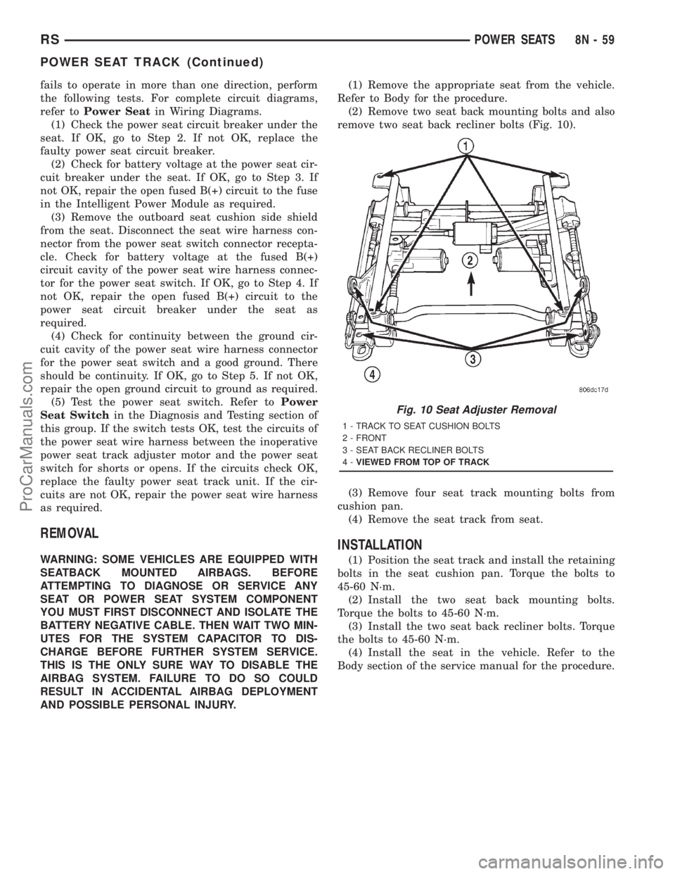
remove two seat back recliner bolts (Fig. 10).
(3) Remove four seat track mounting bolts from
cushion pan.
(4) Remove the seat track from seat.
INSTALLATION
(1) Position the seat track and install the retaining
bolts in the seat cushion pan. Torque the bolts to
45-60 N´m.
(2) Install the two seat back mounting bolts.
Torque the bolts to 45-60 N´m.
(3) Install the two seat back recliner bolts. Torque
the bolts to 45-60 N´m.
(4) Install the seat in the vehicle. Refer to the
Body section of the service manual for the procedure.
Fig. 10 Seat Adjuster Removal
1 - TRACK TO SEAT CUSHION BOLTS
2 - FRONT
3 - SEAT BACK RECLINER BOLTS
4-VIEWED FROM TOP OF TRACK
RSPOWER SEATS8N-59
POWER SEAT TRACK (Continued)
ProCarManuals.com
Page 587 of 2321

(2) Remove cover from seat belt turning loop.
(3) Remove bolt attaching turning loop to shoulder
belt height adjuster (Fig. 2).
(4) Remove turning loop from B-pillar.
(5) Remove lower B-pillar trim cover or quarter
trim panel.
(6) Remove bolt attaching seat belt retractor to
B-pillar (Fig. 2).
(7) Lift retractor upward and disengage arrow
head retainer attaching retractor to B-pillar.
(8) Remove seat belt from vehicle.
INSTALLATION
Inspect the condition of the shoulder belt and lap
belt. Replace any belt that is cut, frayed, torn, or
damaged in any way. Also, replace the shoulder belt
if the retractor is either damaged or inoperative.
(1) Place seat belt into position.
(2) Lower retractor into position B-pillar.
(3) Install bolt attaching seat belt retractor to
B-pillar. Tighten all seat belt anchor bolts to 39 N´m
(29 ft. lbs.) torque.
(4) Install turning loop onto B-pillar.
(5) Install lower B-pillar trim cover or quarter
trim panel.
(6) Install bolt attaching turning loop to shoulder
belt height adjuster. Tighten all seat belt anchor
bolts to 39 N´m (29 ft. lbs.) torque.
(7) Press cover onto the seat belt turning loop.(8) Install shoulder harness height adjuster knob
by pushing onto the adjuster.
SEAT BELT FIRST ROW
ANCHOR BRACKET - LWB
REMOVAL
(1) Remove lower quarter trim panel.
(2) Remove bolt attaching first row seat belt
anchor bracket to floor.
(3) Remove bracket from vehicle.
INSTALLATION
(1) Position bracket to vehicle.
(2) Install bolt attaching first row seat belt anchor
bracket to floor.
(3) Install lower quarter trim panel.
NOTE: The tightening specification for all seat belt
anchor bolts is 39 N´m (29 ft. lbs.) torque.
SEAT BELT LEFT FIRST ROW
OUTBOARD - SWB THREE
DOOR
REMOVAL
(1) Remove first and second row seats. Refer to
Owner's manual for proper procedures.
(2) Remove shoulder harness height adjuster knob
by pulling it straight away from adjuster.
(3) Slide floor anchor cover from over the anchor
bolt.
(4) Remove floor anchor bolt (Fig. 3).
(5) Remove anchor from floor.
(6) Open clam shell cover from over seat belt turn-
ing loop.
(7) Remove bolt attaching turning loop to shoulder
belt height adjuster.
(8) Remove turning loop from C-pillar.
(9) Remove B-pillar upper trim cover.
(10) Remove C-pillar upper trim cover.
(11) Remove lower quarter trim panel.
(12) Route seat belt webbing and turning loop
through access hole in lower quarter trim panel.
(13) Remove bolt attaching seat belt retractor to
quarter panel.
(14) Lift retractor upward and disengage arrow
head retainer attaching retractor to quarter panel
(Fig. 3).
(15) Remove seat belt from vehicle.
Fig. 2 SEAT BELT - OUTBOARD FRONT
1 - B-PILLAR TRIM LOWER
2 - BELT
3 - B-PILLAR TRIM UPPER
4 - HEIGHT ADJUSTER
5 - KNOB
6 - B-PILLAR TRIM LOWER
7 - FLOOR ANCHOR
8 - FLOOR ANCHOR
9 - 30É OUTBOARD
10 - RETRACTOR
8O - 8 RESTRAINTSRS
SEAT BELT OUTBOARD FRONT (Continued)
ProCarManuals.com
Page 588 of 2321

INSTALLATION
(1) Install seat belt into position.
(2) Lower retractor into position to quarter panel.
(3) Install bolt attaching seat belt retractor to
quarter panel. Tighten all seat belt anchor bolts to 39
N´m (29 ft. lbs.) torque.
(4) Install lower quarter trim panel.
(5) Install C-pillar upper trim cover.
(6) Route seat belt webbing and turning loop
through access hole in lower quarter trim panel.
(7) Install B-pillar upper trim cover.
(8) Install turning loop onto C-pillar. Tighten all
seat belt anchor bolts to 39 N´m (29 ft. lbs.) torque.
(9) Press clam shell cover over seat belt turning
loop.
(10) Install anchor to floor.
(11) Slide floor anchor cover over the anchor bolt.
(12) Install shoulder harness height adjuster knob
by pushing it onto adjuster.
(13) Install first and second row seats.
SEAT BELT FIRST ROW
OUTBOARD - SWB FOUR
DOOR
REMOVAL
(1) Remove first and second row seats. Refer to
Owner's manual for proper procedures.
(2) Remove shoulder harness height adjuster knob
by pulling it straight away from adjuster.
(3) Slide floor anchor cover from over the anchor
bolt.
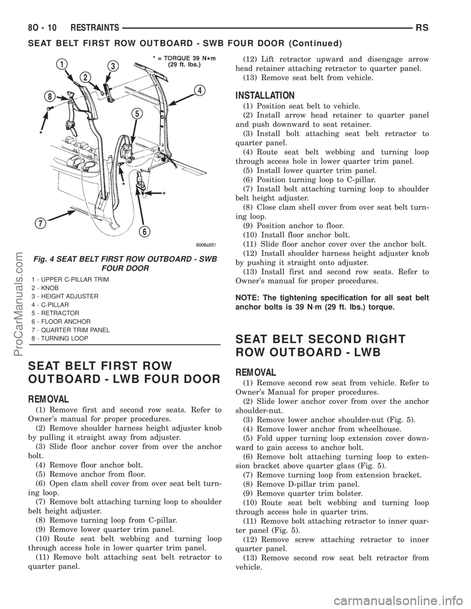
(4) Remove floor anchor bolt (Fig. 4).
(5) Remove anchor from floor.
(6) Open clam shell cover from over seat belt turn-
ing loop.
(7) Remove bolt attaching turning loop to shoulder
belt height adjuster (Fig. 4).
(8) Remove turning loop from C-pillar.
(9) Remove lower quarter trim panel.
(10) Route seat belt webbing and turning loop
through access hole in lower quarter trim panel.
(11) Remove bolt attaching seat belt retractor to
quarter panel (Fig. 4).
(12) Lift retractor upward and disengage arrow
head retainer holding retractor to quarter panel.
(13) Remove seat belt from vehicle.
INSTALLATION
(1) Install seat belt into position.
(2) Lower retractor into position to quarter panel.
(3) Install bolt attaching seat belt retractor to
quarter panel. Tighten seat belt anchor bolts to 39
N´m (29 ft. lbs.) torque.
(4) Route seat belt webbing and turning loop
through access hole in lower quarter trim panel.
(5) Install lower quarter trim panel.
(6) Install turning loop in position on C-pillar.
Tighten seat belt anchor bolts to 39 N´m (29 ft. lbs.)
torque.
(7) Install bolt attaching turning loop to shoulder
belt height adjuster. Tighten seat belt anchor bolts to
39 N´m (29 ft. lbs.) torque.
(8) Close clam shell cover over seat belt turning
loop.
(9) Place anchor in position on floor.
(10) Install floor anchor bolt. Tighten seat belt
anchor bolts to 39 N´m (29 ft. lbs.) torque.
(11) Slide floor anchor cover over the anchor bolt.
(12) Install shoulder harness height adjuster knob
by pushing knob on the adjuster.
Fig. 3 Seat Belt Left First Row Outboard ± SWB
Three Door
1 - C-PILLAR TRIM
2 - KNOB
3 - RETRACTOR
4 - LOWER ANCHOR
5 - QUARTER TRIM
RSRESTRAINTS8O-9
SEAT BELT LEFT FIRST ROW OUTBOARD - SWB THREE DOOR (Continued)
ProCarManuals.com
Page 589 of 2321
SEAT BELT FIRST ROW
OUTBOARD - LWB FOUR DOOR
REMOVAL
(1) Remove first and second row seats. Refer to
Owner's manual for proper procedures.
(2) Remove shoulder harness height adjuster knob
by pulling it straight away from adjuster.
(3) Slide floor anchor cover from over the anchor
bolt.
(4) Remove floor anchor bolt.
(5) Remove anchor from floor.
(6) Open clam shell cover from over seat belt turn-
ing loop.
(7) Remove bolt attaching turning loop to shoulder
belt height adjuster.
(8) Remove turning loop from C-pillar.
(9) Remove lower quarter trim panel.
(10) Route seat belt webbing and turning loop
through access hole in lower quarter trim panel.
(11) Remove bolt attaching seat belt retractor to
quarter panel.(12) Lift retractor upward and disengage arrow
head retainer attaching retractor to quarter panel.
(13) Remove seat belt from vehicle.
INSTALLATION
(1) Position seat belt to vehicle.
(2) Install arrow head retainer to quarter panel
and push downward to seat retainer.
(3) Install bolt attaching seat belt retractor to
quarter panel.
(4) Route seat belt webbing and turning loop
through access hole in lower quarter trim panel.
(5) Install lower quarter trim panel.
(6) Position turning loop to C-pillar.
(7) Install bolt attaching turning loop to shoulder
belt height adjuster.
(8) Close clam shell cover from over seat belt turn-
ing loop.
(9) Position anchor to floor.
(10) Install floor anchor bolt.
(11) Slide floor anchor cover over the anchor bolt.
(12) Install shoulder harness height adjuster knob
by pushing it straight onto adjuster.
(13) Install first and second row seats. Refer to
Owner's manual for proper procedures.
NOTE: The tightening specification for all seat belt
anchor bolts is 39 N´m (29 ft. lbs.) torque.
SEAT BELT SECOND RIGHT
ROW OUTBOARD - LWB
REMOVAL
(1) Remove second row seat from vehicle. Refer to
Owner's Manual for proper procedures.
(2) Slide lower anchor cover from over the anchor
shoulder-nut.
(3) Remove lower anchor shoulder-nut (Fig. 5).
(4) Remove lower anchor from wheelhouse.
(5) Fold upper turning loop extension cover down-
ward to gain access to anchor bolt.
(6) Remove bolt attaching turning loop to exten-
sion bracket above quarter glass (Fig. 5).
(7) Remove turning loop from extension bracket.
(8) Remove D-pillar trim panel.
(9) Remove quarter trim bolster.
(10) Route seat belt webbing and turning loop
through access hole in quarter trim.
(11) Remove bolt attaching retractor to inner quar-
ter panel (Fig. 5).
(12) Remove screw attaching retractor to inner
quarter panel.
(13) Remove second row seat belt retractor from
vehicle.
Fig. 4 SEAT BELT FIRST ROW OUTBOARD - SWB
FOUR DOOR
1 - UPPER C-PILLAR TRIM
2 - KNOB
3 - HEIGHT ADJUSTER
4 - C-PILLAR
5 - RETRACTOR
6 - FLOOR ANCHOR
7 - QUARTER TRIM PANEL
8 - TURNING LOOP
8O - 10 RESTRAINTSRS
SEAT BELT FIRST ROW OUTBOARD - SWB FOUR DOOR (Continued)
ProCarManuals.com
Page 618 of 2321
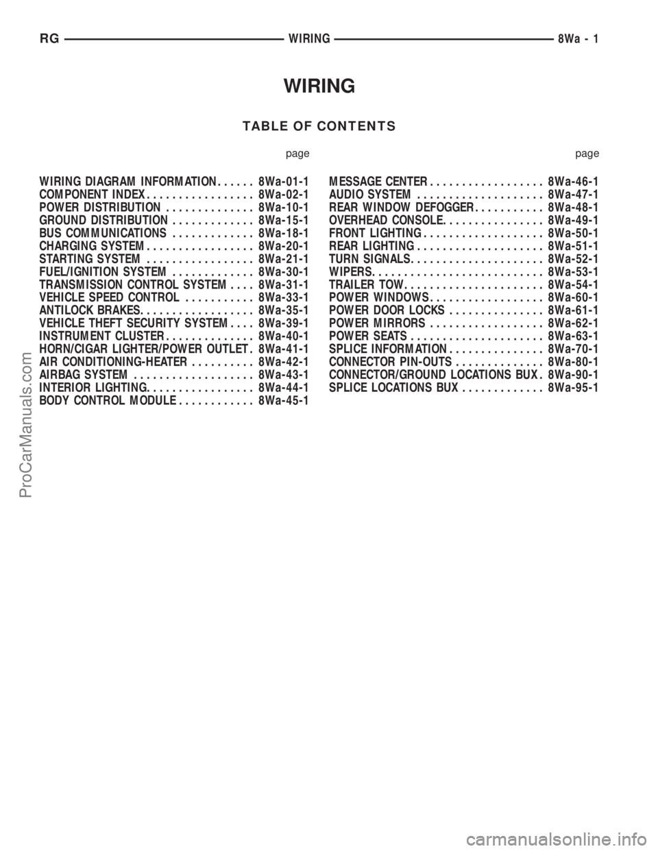
WIRING
TABLE OF CONTENTS
page page
WIRING DIAGRAM INFORMATION...... 8Wa-01-1
COMPONENT INDEX................. 8Wa-02-1
POWER DISTRIBUTION.............. 8Wa-10-1
GROUND DISTRIBUTION............. 8Wa-15-1
BUS COMMUNICATIONS............. 8Wa-18-1
CHARGING SYSTEM................. 8Wa-20-1
STARTING SYSTEM................. 8Wa-21-1
FUEL/IGNITION SYSTEM............. 8Wa-30-1
TRANSMISSION CONTROL SYSTEM.... 8Wa-31-1
VEHICLE SPEED CONTROL........... 8Wa-33-1
ANTILOCK BRAKES.................. 8Wa-35-1
VEHICLE THEFT SECURITY SYSTEM.... 8Wa-39-1
INSTRUMENT CLUSTER.............. 8Wa-40-1
HORN/CIGAR LIGHTER/POWER OUTLET . 8Wa-41-1
AIR CONDITIONING-HEATER.......... 8Wa-42-1
AIRBAG SYSTEM................... 8Wa-43-1
INTERIOR LIGHTING................. 8Wa-44-1
BODY CONTROL MODULE............ 8Wa-45-1MESSAGE CENTER.................. 8Wa-46-1
AUDIO SYSTEM.................... 8Wa-47-1
REAR WINDOW DEFOGGER........... 8Wa-48-1
OVERHEAD CONSOLE................ 8Wa-49-1
FRONT LIGHTING................... 8Wa-50-1
REAR LIGHTING.................... 8Wa-51-1
TURN SIGNALS..................... 8Wa-52-1
WIPERS........................... 8Wa-53-1
TRAILER TOW...................... 8Wa-54-1
POWER WINDOWS.................. 8Wa-60-1
POWER DOOR LOCKS............... 8Wa-61-1
POWER MIRRORS.................. 8Wa-62-1
POWER SEATS..................... 8Wa-63-1
SPLICE INFORMATION............... 8Wa-70-1
CONNECTOR PIN-OUTS.............. 8Wa-80-1
CONNECTOR/GROUND LOCATIONS BUX . 8Wa-90-1
SPLICE LOCATIONS BUX............. 8Wa-95-1 RGWIRING
8Wa-1
ProCarManuals.com
Page 960 of 2321

8W-63 POWER SEATS
Component Page
Body Control Module............... 8Wa-63-4, 7
Diagnostic Junction Port.............. 8Wa-63-4
Driver Heated Seat Back............. 8Wa-63-7
Driver Heated Seat Cushion........... 8Wa-63-7
Driver Heated Seat Module........ 8Wa-63-3, 4, 7
Driver Power Seat Front Riser Motor.... 8Wa-63-2
Driver Power Seat Horizontal Motor..... 8Wa-63-2
Driver Power Seat Rear Riser Motor..... 8Wa-63-2
Driver Power Seat Recliner Motor...... 8Wa-63-2
Driver Power Seat Switch............. 8Wa-63-2
Fuse 22 (IPM).................... 8Wa-63-2, 4
G200....................... 8Wa-63-2, 4, 5, 7
G301........................... 8Wa-63-3, 8
Instrument Panel Switch Bank......... 8Wa-63-7
Intelligent Power Module........... 8Wa-63-2, 4
Memory Power Seat Switch........... 8Wa-63-5
Memory Seat Front Vertical Motor...... 8Wa-63-5
Memory Seat Front Vertical Position Sensor. 8Wa-63-6
Memory Seat Horizontal Motor......... 8Wa-63-5
Memory Seat Horizontal Position Sensor . 8Wa-63-6
Memory Seat Rear Vertical Motor....... 8Wa-63-5
Memory Seat Rear Vertical Position Sensor. 8Wa-63-6
Memory Seat Recliner Motor........... 8Wa-63-5
Memory Seat Recliner Position Sensor . . . 8Wa-63-6
Memory Seat Switch................. 8Wa-63-4
Memory Seat/Mirror Module....... 8Wa-63-4, 5, 6
Passenger Heated Seat Back........... 8Wa-63-8
Passenger Heated Seat Cushion........ 8Wa-63-8
Passenger Heated Seat Module......... 8Wa-63-8
Passenger Power Seat Front Riser Motor . 8Wa-63-3
Passenger Power Seat Horizontal Motor . . 8Wa-63-3
Passenger Power Seat Rear Riser Motor . . 8Wa-63-3
Passenger Power Seat Recliner Motor.... 8Wa-63-3
Passenger Power Seat Switch.......... 8Wa-63-3
Power Seat Circuit Breaker........ 8Wa-63-2, 3, 4
RG8W-63 POWER SEATS8Wa-63-1
ProCarManuals.com