2001 DODGE TOWN AND COUNTRY back
[x] Cancel search: backPage 2097 of 2321

EXTERIOR
TABLE OF CONTENTS
page page
BODY SIDE MOLDINGS
REMOVAL.............................184
INSTALLATION..........................184
COWL GRILLE
REMOVAL.............................190
INSTALLATION..........................190
EXTERIOR NAME PLATES - TAPE ATTACHED
REMOVAL.............................191
INSTALLATION..........................191
EXTERIOR NAME PLATES - ADHESIVE
ATTACHED
REMOVAL.............................191
INSTALLATION..........................191
FRONT FENDER
REMOVAL.............................191
INSTALLATION..........................191
FUEL FILL DOOR
REMOVAL.............................191
INSTALLATION..........................192
FUEL FILL DOOR BLOCKER LATCH
REMOVAL.............................192
INSTALLATION..........................192
FUEL FILL DOOR BLOCKER LATCH STRIKER
REMOVAL.............................193
INSTALLATION..........................193
FUEL FILL DOOR BLOCKER LOCKOUT LINK
REMOVAL.............................193INSTALLATION..........................193
GRILLE OPENING REINFORCEMENT
REMOVAL.............................194
INSTALLATION..........................194
FRONT WHEELHOUSE SPLASH SHIELD
REMOVAL.............................194
INSTALLATION..........................195
LUGGAGE RACK RISER
REMOVAL.............................195
INSTALLATION..........................195
LUGGAGE RACK CROSSBAR
REMOVAL.............................195
INSTALLATION..........................196
REAR QUARTER PANEL/FENDER AIR
EXHAUSTER
DESCRIPTION..........................196
REMOVAL.............................196
INSTALLATION..........................197
ROOF JOINT MOLDING
REMOVAL.............................197
INSTALLATION..........................197
SIDE VIEW MIRROR
REMOVAL.............................198
INSTALLATION..........................198
BODY SIDE MOLDINGS
REMOVAL
Refer to (Fig. 1), (Fig. 2), (Fig. 3), (Fig. 4) or (Fig.
5)for proper location of fasteners holding the molding
to the wheelhouse lip and rocker panels.
(1) Warm the affected stick-on molding and body
metal to approximately 38É C (100É F) using a suit-
able heat lamp or heat gun.
(2) If equipped, remove pop-rivets holding molding
edge to wheelhouse lip.
(3) Pull stick-on molding from painted surface.
(4) Remove adhesive tape residue from painted
surface of vehicle. Use a 3M Scotch-BriteŸ Molding
Adhesive and Stripe Removal Disc, or equivalent, to
clean adhesive residue from painted surfaces. These
products are available from automotive paint suppli-
ers. Refer to instructions supplied with the specific
product for proper usage.
INSTALLATION
Refer to (Fig. 1) , (Fig. 2), (Fig. 3), (Fig. 4) or (Fig.
5)for proper location of fasteners to hold the molding
to the wheelhouse lip and rocker panels.
(1) If molding is to be reused;
(a) Remove tape residue from molding.
(b) Clean back of molding with Moparž Super
Kleen, or equivalent.
(c) Wipe molding dry with lint free cloth.
(d) Apply a single coat of Moparž TPO Molding
Prep to tape side of molding and allow to dry thor-
oughly.
(e) Apply new body side molding (two sided
adhesive) tape to back of molding.
(2) Clean body surface with Moparž Super Kleen,
or equivalent. Wipe surface dry with lint free cloth.
(3) Remove protective cover from tape on back of
molding.
(4) Apply molding to body from front to rear,
inserting locator pins into hole in body panel.
23 - 184 EXTERIORRS
ProCarManuals.com
Page 2109 of 2321
INSTALLATION
NOTE: The crossbar assemblies are designed to be
installed in only one way. Check top and bottom
surfaces of the crossbar for the word FRONT and
directional arrows. The directional arrows must
point toward the front of the vehicle.
(1) Place crossbar in position on vehicle.
(2) Work from side to side sliding the crossbar
assembly back a little at a time to ensure it remains
perpendicular to the side rails.
(3) Position first crossbar assembly crossbar at the
second most rearward locator holes. Press the top of
the stanchion lever to lock it into position.
(4) Position the second crossbar assembly in the
second hole from the front. Lock into place.
(5) Place luggage rack riser into position.
(6) Install two fasteners into riser. Tighten fasten-
ers to 4 mm (35 in. lbs.) torque.
REAR QUARTER PANEL/
FENDER AIR EXHAUSTER
DESCRIPTION
Air exhausters, designed to conform to the body
structure, allow air entering at the front of the vehi-
cle to flow out the back. By reducing air pressure
within the vehicle, the exhausters also reduce blower
noise at any given air flow level compared to operat-
ing without them and help reduce door closing effort.
They are located in the lower rear comers of the
body.
REMOVAL
SHORT WHEELBASE
(1) Remove the rear fascia from the body. (Refer to
13 - FRAMES & BUMPERS/BUMPERS/REAR FAS-
CIA - REMOVAL).
(2) Using a trim stick or another suitable wide flat
bladed tool, carefully pry the air exhauster away
from the opening in the lower aperture panel until
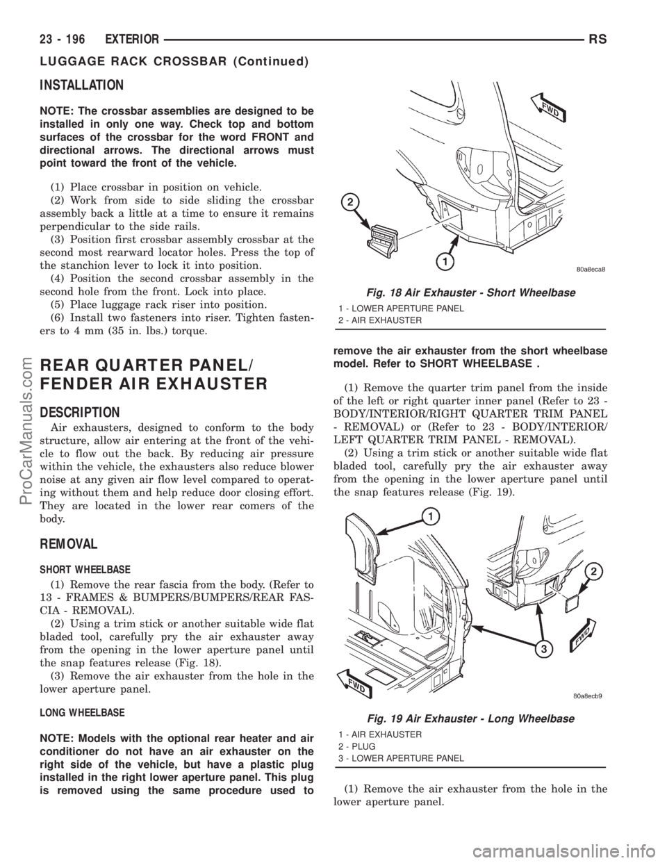
the snap features release (Fig. 18).
(3) Remove the air exhauster from the hole in the
lower aperture panel.
LONG WHEELBASE
NOTE: Models with the optional rear heater and air
conditioner do not have an air exhauster on the
right side of the vehicle, but have a plastic plug
installed in the right lower aperture panel. This plug
is removed using the same procedure used toremove the air exhauster from the short wheelbase
model. Refer to SHORT WHEELBASE .
(1) Remove the quarter trim panel from the inside
of the left or right quarter inner panel (Refer to 23 -
BODY/INTERIOR/RIGHT QUARTER TRIM PANEL
- REMOVAL) or (Refer to 23 - BODY/INTERIOR/
LEFT QUARTER TRIM PANEL - REMOVAL).
(2) Using a trim stick or another suitable wide flat
bladed tool, carefully pry the air exhauster away
from the opening in the lower aperture panel until
the snap features release (Fig. 19).
(1) Remove the air exhauster from the hole in the
lower aperture panel.
Fig. 18 Air Exhauster - Short Wheelbase
1 - LOWER APERTURE PANEL
2 - AIR EXHAUSTER
Fig. 19 Air Exhauster - Long Wheelbase
1 - AIR EXHAUSTER
2 - PLUG
3 - LOWER APERTURE PANEL
23 - 196 EXTERIORRS
LUGGAGE RACK CROSSBAR (Continued)
ProCarManuals.com
Page 2110 of 2321

INSTALLATION
SHORT WHEELBASE
(1) Position the air exhauster to the hole in the
lower aperture panel (Fig. 18).
(2) Using hand pressure, press the air exhauster
into the opening in the lower aperture panel until
the snap features are fully engaged.
(3) Reinstall the rear fascia onto the body. (Refer
to 13 - FRAMES & BUMPERS/BUMPERS/REAR
FASCIA - INSTALLATION).
LONG WHEELBASE
NOTE: Models with the optional rear heater and air
conditioner do not have an air exhauster on the
right side of the vehicle, but have a plastic plug
installed in the right lower aperture panel. This plug
is installed using the same procedure used to
install the air exhauster onto the short wheelbase
model. Refer to SHORT WHEELBASE .
(1) Position the air exhauster to the hole in the
lower aperture panel (Fig. 19).
(2) Using hand pressure, press the air exhauster
into the opening in the lower aperture panel until
the snap features are fully engaged.
(3) Reinstall the quarter trim panel onto the inside
of the left or right quarter inner panel. (Refer to 23 -
BODY/INTERIOR/RIGHT QUARTER TRIM PANEL
- INSTALLATION) or (Refer to 23 - BODY/INTERI-
OR/LEFT QUARTER TRIM PANEL - INSTALLA-
TION).
ROOF JOINT MOLDING
REMOVAL
The RAP molding is set with body side molding
tape. The temperature in the work area and the vehi-cle should be at least 21É C (70É F) to avoid damag-
ing the RAP moldings.
(1) Warm the affected stick-on molding and body
metal to approximately 38É C (100É F) using a suit-
able heat lamp or heat gun.
(2) Pull stick-on molding from painted surface.
(3) Remove adhesive tape residue from painted
surface of vehicle. Use a 3M Scotch-BriteŸ Molding
Adhesive and Stripe Removal Discs, or equivalent, to
clean adhesive residue from painted surfaces. The
adhesive removal discs are available from automotive
paint suppliers. Refer to instructions supplied with
the discs for proper usage.
INSTALLATION
The RAP molding is set with body side molding
tape. The temperature in the work area and the vehi-
cle should be at least 21É C (70É F) to avoid damag-
ing the RAP moldings.
(1) If molding is to be reused;
(a) Remove tape residue from molding.
(b) Clean back of molding with Moparž Super
Kleen solvent, or equivalent.
(c) Wipe molding dry with lint free cloth.
(d) Apply new body side molding (two sided
adhesive) tape to back of molding.
(2) Clean body surface with Moparž Super Kleen
solvent, or equivalent. Wipe surface dry with lint free
cloth.
(3) Remove protective cover from tape on back of
molding.
(4) Apply molding to body from front of vehicle to
rear.
(5) Using a roller tool, roll molding onto body
panel with enough force to assure adhesion and not
bend roof panels.
RSEXTERIOR23 - 197
REAR QUARTER PANEL/FENDER AIR EXHAUSTER (Continued)
ProCarManuals.com
Page 2114 of 2321
(4) Align hood latch by placing latch over net
pierced tabs. If alignment is required, flatten or
grind tabs.
(5) Verify hood operation and alignment. Adjust as
necessary.
(6) Tighten attaching bolts to 13.5 N´m (10 ft. lbs.)
torque.
LATCH RELEASE CABLE
REMOVAL
(1) Remove hood latch.
(2) Disengage cable end from hood latch locking
mechanism.
(3) Slide cable case end sideways in keyhole slot of
hood latch while pinching barb on cable case closed.
(4) Remove cable from latch (Fig. 4).
(5) Remove hood release handle from instrument
panel.
(6) Disengage rubber grommet cable insulator
from hole in dash panel.
(7) Attach a suitable length of mechanic's wire to
latch end of cable to assist cable installation.
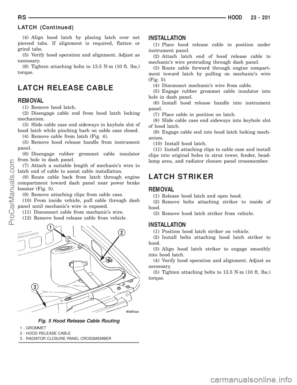
(8) Route cable back from latch through engine
compartment toward dash panel near power brake
booster (Fig. 5).
(9) Remove attaching clips from cable case.
(10) From inside vehicle, pull cable through dash
panel until mechanic's wire is exposed.
(11) Disconnect cable from mechanic's wire.
(12) Remove hood release cable from vehicle.
INSTALLATION
(1) Place hood release cable in position under
instrument panel.
(2) Attach latch end of hood release cable to
mechanic's wire protruding through dash panel.
(3) Route cable forward through engine compart-
ment toward latch by pulling on mechanic's wire
(Fig. 5).
(4) Disconnect mechanic's wire from cable.
(5) Engage rubber grommet cable insulator into
hole in dash panel.
(6) Install hood release handle into instrument
panel.
(7) Place cable in position on latch.
(8) Slide cable case end sideways into keyhole slot
of hood latch.
(9) Engage cable end into hood latch locking mech-
anism.
(10) Install hood latch.
(11) Install attaching clips to cable case and install
clips into original holes in strut tower, fender, head-
lamp area, and radiator closure panel crossmember.
LATCH STRIKER
REMOVAL
(1) Release hood latch and open hood.
(2) Remove bolts attaching striker to inside of
hood.
(3) Remove hood latch striker from vehicle.
INSTALLATION
(1) Position hood latch striker on vehicle.
(2) Install bolts attaching hood latch striker to
hood.
(3) Align hood latch striker to engage smoothly
into hood latch.
(4) Verify hood operation and alignment. Adjust as
necessary.
(5) Tighten attaching bolts to 13.5 N´m (10 ft. lbs.)
torque.
Fig. 5 Hood Release Cable Routing
1 - GROMMET
2 - HOOD RELEASE CABLE
3 - RADIATOR CLOSURE PANEL CROSSMEMBER
RSHOOD23 - 201
LATCH (Continued)
ProCarManuals.com
Page 2115 of 2321
INSTRUMENT PANEL
TABLE OF CONTENTS
page page
CLUSTER BEZEL
REMOVAL.............................202
INSTALLATION..........................202
CUP HOLDER
REMOVAL.............................202
INSTALLATION..........................202
GLOVE BOX
REMOVAL.............................203
INSTALLATION..........................203
GLOVE BOX LATCH
REMOVAL.............................203
INSTALLATION..........................203
GLOVE BOX LATCH STRIKER
REMOVAL.............................203
INSTALLATION..........................203
INSTRUMENT PANEL ASSEMBLY
REMOVAL.............................203
INSTALLATION..........................204
INSTRUMENT PANEL CENTER BEZEL
REMOVAL.............................205
INSTALLATION..........................205INSTRUMENT PANEL END COVER
REMOVAL.............................205
INSTALLATION..........................205
INSTRUMENT PANEL TOP COVER
REMOVAL.............................205
INSTALLATION..........................206
KNEE BLOCKER REINFORCEMENT
REMOVAL.............................206
INSTALLATION..........................206
LOWER CONSOLE
REMOVAL.............................206
INSTALLATION..........................206
LOWER INSTRUMENT PANEL
REMOVAL.............................206
INSTALLATION..........................206
LOWER STEERING COLUMN COVER
REMOVAL.............................206
INSTALLATION..........................206
OVER STEERING COLUMN COVER
REMOVAL.............................207
INSTALLATION..........................207
CLUSTER BEZEL
REMOVAL
(1) Disconnect and isolate the battery negative
cable.
(2) Remove Over Steering Column Bezel by lifting
it straight up with a firm pull.
(3) Remove the four bezel attaching screws.
(4) Tilt the steering column in the full down posi-
tion.
(5) Pull rearward on the cluster bezel and remove.
INSTALLATION
(1) Manuever cluster bezel over steering column
and into position.
(2) Install the four bezel attaching screws.
(3) Install the Over Steering Column Bezel by
positioning it over the retaining slots and firmly
snapping it into place.
(4) Connect the battery negative cable.
CUP HOLDER
REMOVAL
(1) Remove the cup holder. Pull the cup holder out
and depress the tang in the middle back and pull
rearward to release the cup holder.
(2) Remove the screw access cover from the bottom
of the center bezel.
(3) Using a trim stick (special tool #C-4755) or
equivalent, gently pry out on the edge of the instru-
ment panel center bezel. Hang off to the side leaving
the accessory switches connected.
(4) Remove the cup holder assembly attaching
screws and pull the assembly rearward to disengage
the rear guide studs from instrument panel.
(5) Remove the cup holder track assembly.
INSTALLATION
(1) Install the cup holder track assembly.
(2) Place the cup holder track assembly into posi-
tion and slide into opening in instrument panel until
the rear guide struts snap into place. Install the cup
holder assembly attaching screws.
(3) Install the center bezel.
(4) Install the screw access cover from the bottom
of the center bezel.
23 - 202 INSTRUMENT PANELRS
ProCarManuals.com
Page 2125 of 2321
(9) Install lower B-pillar trim covers.
(10) Install rear door sill plate.
(11) Install sliding door sill plates. (Refer to 23 -
BODY/INTERIOR/SLIDING DOOR SILL PLATE -
INSTALLATION).
(12) Install front cowl panels and sill plates.
(13) Install the passenger seats. Refer to the Own-
er's Manual for proper procedures.
(14) Install front center console.
(15) Install front seats. (Refer to 23 - BODY/
SEATS/SEAT - INSTALLATION).
COWL TRIM
REMOVAL
(1) Remove door sill plate.
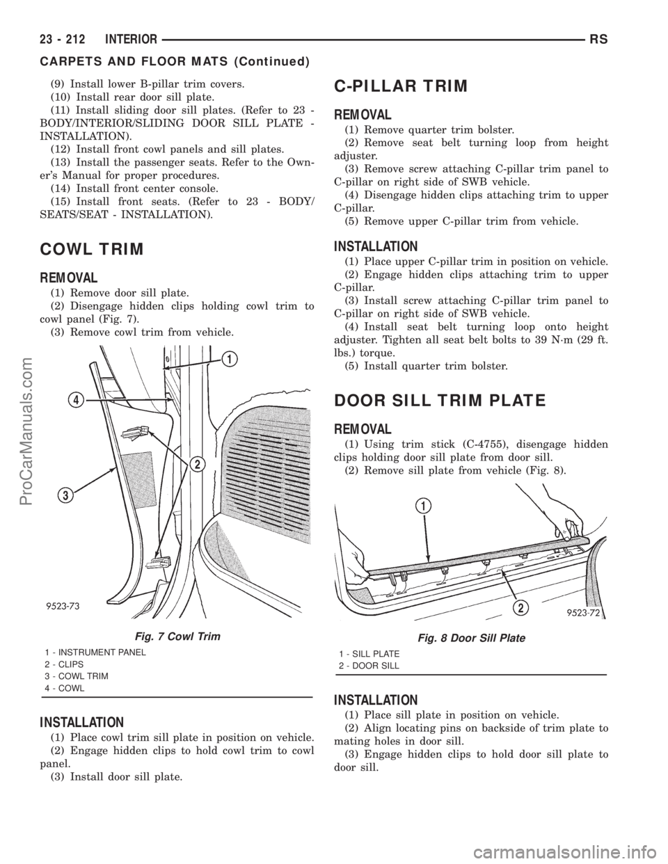
(2) Disengage hidden clips holding cowl trim to
cowl panel (Fig. 7).
(3) Remove cowl trim from vehicle.
INSTALLATION
(1) Place cowl trim sill plate in position on vehicle.
(2) Engage hidden clips to hold cowl trim to cowl
panel.
(3) Install door sill plate.
C-PILLAR TRIM
REMOVAL
(1) Remove quarter trim bolster.
(2) Remove seat belt turning loop from height
adjuster.
(3) Remove screw attaching C-pillar trim panel to
C-pillar on right side of SWB vehicle.
(4) Disengage hidden clips attaching trim to upper
C-pillar.
(5) Remove upper C-pillar trim from vehicle.
INSTALLATION
(1) Place upper C-pillar trim in position on vehicle.
(2) Engage hidden clips attaching trim to upper
C-pillar.
(3) Install screw attaching C-pillar trim panel to
C-pillar on right side of SWB vehicle.
(4) Install seat belt turning loop onto height
adjuster. Tighten all seat belt bolts to 39 N´m (29 ft.
lbs.) torque.
(5) Install quarter trim bolster.
DOOR SILL TRIM PLATE
REMOVAL
(1) Using trim stick (C-4755), disengage hidden
clips holding door sill plate from door sill.
(2) Remove sill plate from vehicle (Fig. 8).
INSTALLATION
(1) Place sill plate in position on vehicle.
(2) Align locating pins on backside of trim plate to
mating holes in door sill.
(3) Engage hidden clips to hold door sill plate to
door sill.
Fig. 7 Cowl Trim
1 - INSTRUMENT PANEL
2 - CLIPS
3 - COWL TRIM
4 - COWL
Fig. 8 Door Sill Plate
1 - SILL PLATE
2 - DOOR SILL
23 - 212 INTERIORRS
CARPETS AND FLOOR MATS (Continued)
ProCarManuals.com
Page 2127 of 2321

INSTALLATION
LONG WHEEL BASE
(1) Place jack storage cover in position on vehicle.
(2) Align guide pins.
(3) Push inward at top of cover to engage latch
and fastener.
SHORT WHEEL BASE
(1) Position jack storage cover to vehicle.
(2) Snap storage cover latch into position on quar-
ter trim panel.
(3) Close quarter trim panel bin storage cover.
LEFT D-PILLAR TRIM PANEL
REMOVAL
(1) Remove rear header trim cover.
(2) Remove liftgate sill plate.
(3) Remove second row seat belt turning loop on
long wheel base vehicle.
(4) Remove bolt attaching second row seat belt
lower anchor to quarter on short wheel base vehicle.
(5) Remove jack storage cover.
(6) Remove screws attaching trim panel to D-pil-
lar.
(7) Disengage hidden clips attaching trim to D-pil-
lar.
(8) Disconnect speaker wire connector, if equipped.
(9) Pass seat belt through slot in D-pillar trim
panel on short wheel base vehicle.
(10) Remove D-pillar trim from vehicle.
INSTALLATION
(1) Pass seat belt through slot in D-pillar trim
panel on short wheel base vehicle.
(2) Position D-pillar trim panel on vehicle.
(3) Connect speaker wire connector to speaker, if
equipped.
(4) Align locating pins on backside of trim panel to
mating holes in inner quarter panel.
(5) Engage hidden clips attaching trim to D-pillar.
(6) Install screws attaching trim to D-pillar.
(7) Install jack storage cover.
(8) Install bolt attaching second row seat belt
lower anchor to quarter on short wheel base vehicle.
Tighten all seat belt bolts to 39 N´m (29 ft. lbs.).
(9) Install second row seat belt turning loop on
long wheel base vehicle.
(10) Install liftgate sill plate.
(11) Install rear header trim cover.
LIFTGATE SCUFF PLATE
REMOVAL
(1) Disengage hidden clips holding sill plate to lift-
gate door opening sill (Fig. 11) .
(2) Remove sill plate from vehicle.
INSTALLATION
(1) Place sill plate in position on vehicle.
(2) Align locator rib into recess in liftgate sill.
(3) Engage hidden clips to hold sill plate to liftgate
door opening sill.
QUARTER TRIM BOLSTER
REMOVAL
The speaker grille in the quarter trim bolster is
not removable. The trim bolster must removed to ser-
vice the speaker.
(1) Disengage hidden clips attaching trim bolster
to quarter trim panel.
(2) Disengage hook retainer attaching front of trim
bolster to quarter trim panel, if applicable.
(3) Remove quarter trim bolster from vehicle.
INSTALLATION
The speaker grille in the quarter trim bolster is
not removable. The trim bolster must removed to ser-
vice the speaker.
(1) Place quarter trim bolster in position on vehi-
cle.
(2) Engage hook retainer attaching front of trim
bolster to quarter trim panel, if applicable.
(3) Engage hidden clips attaching trim bolster to
quarter trim panel.
Fig. 11 Liftgate Sill Plate
1 - LIFTGATE SILL PLATE
2 - LIFTGATE SILL
23 - 214 INTERIORRS
JACK STORAGE COVER (Continued)
ProCarManuals.com
Page 2128 of 2321
RIGHT QUARTER TRIM PANEL
REMOVAL
CAUTION: Disconnect the battery negative cable.
Damage to accessory feed circuit can result.
(1) Remove first row seat.
(2) Remove second row seat, if equipped.
(3) Remove sliding door sill trim panel.
(4) Remove quarter trim bolster.
(5) Remove C-pillar trim panel.
(6) Remove D-pillar trim panel.
(7) Remove first row seat belt anchor.
(8) Remove second row seat belt anchor on long
wheel base vehicle.
(9) Remove screws attaching quarter trim to quar-
ter panel from bolster area.
(10) Remove screws attaching rear edge of quarter
trim to attaching bracket.
(11) Disengage hidden clips holding front of quar-
ter trim to quarter panel rearward of sliding door
opening.
(12) Remove quarter trim from quarter panel.
(13) Disconnect wire connector from accessory
power outlet, if equipped.
(14) Pass second row seat belt through slot in trim
panel on long wheel base vehicle.
(15) Pass first row seat belt through slot in trim
panel.
(16) Remove quarter trim panel from vehicle.
INSTALLATION
(1) Position quarter trim panel on vehicle.
(2) Pass first row seat belt through slot in trim
panel.
(3) Pass second row seat belt through access hole
in trim panel on long wheel base vehicle.
(4) Connect wire connector into accessory power
outlet, if equipped.
(5) Align locating pins on backside of trim panel to
mating holes in inner quarter panel.
(6) Engage hidden clips attaching front of quarter
trim to quarter panel rearward of sliding door open-
ing.
(7) Install screws attaching rear edge of quarter
trim to attaching bracket.
(8) Install screws attaching quarter trim to inner
quarter panel in bolster area.
(9) Install second row seat belt anchor on long
wheel base vehicle. Tighten all seat belt bolts to 39
N´m (29 ft. lbs.) torque.
(10) Install first row seat belt anchor.
(11) Install D-pillar trim panel.
(12) Install C-pillar trim panel.
(13) Install quarter trim bolster.(14) Install sliding door sill trim panel.
(15) Install second row seat, if equipped.
(16) Install first row seat.
(17) Connect the battery negative cable.
LEFT QUARTER TRIM PANEL
REMOVAL
CAUTION: Disconnect the negative cable clamp
from battery post. Damage to accessory feed circuit
can result.
(1) Remove first row seat.
(2) Remove second row seat, if equipped.
(3)
Remove front door sill plate on three door vehicle.
(4) Remove sliding door sill plate on four door
vehicle.
(5) Remove left quarter trim bolster.
(6) Remove upper left B-pillar trim on three door
vehicle.
(7) Remove C-pillar trim panel.
(8) Remove left D-pillar trim panel.
(9) Remove first row seat belt anchor.
(10) Remove second row seat belt anchor on long
wheel base vehicle.
(11) Remove left front seat belt opening bezel from
quarter trim on three door vehicle.
(12) Remove screws attaching quarter trim to
quarter panel in B-pillar area on three door vehicle.
(13) Remove screws attaching quarter trim to
quarter panel from bolster area.
(14)
Remove screws attaching rear edge of quarter
trim to attaching bracket or inner quarter trim panel.
(15) Remove screws attaching top of trim panel to
inner sheet metal between B-pillar and C-pillar on
three door vehicle.
(16) Disconnect wire connector from accessory
power outlet, if equipped.
(17) Remove quarter trim from quarter panel.
(18) Pass front seat belt and turning loop through
slot in quarter trim panel on three door vehicle.
(19) Pass first row seat belt through slot in quar-
ter trim panel.
(20) Pass second row seat belt, if equipped,
through slot in quarter trim panel on long wheel
base vehicle.
(21) Remove quarter trim panel from vehicle.
INSTALLATION
(1) Position quarter trim panel on vehicle.
(2) Pass second row seat belt, if equipped, through
slot in quarter trim panel on long wheel base vehicle.
(3) Pass first row seat belt through slot in quarter
trim panel.
RSINTERIOR23 - 215
ProCarManuals.com