2001 DODGE TOWN AND COUNTRY instrument panel
[x] Cancel search: instrument panelPage 1469 of 2321
WARNING: SAFETY GOGGLES SHOULD BE WORN
AT ALL TIMES WHEN WORKING ON STEERING
COLUMNS.
CAUTION: Disconnect negative (ground) cable from
the battery before servicing any column compo-
nent.
CAUTION: Do not attempt to remove the pivot pins
to disassemble the tilting mechanism. Damage will
occur.
DIAGNOSIS AND TESTING
For diagnosis of conditions relating to the steering
column (Refer to 19 - STEERING - DIAGNOSIS AND
TESTING) and (Refer to 19 - STEERING - DIAGNO-
SIS AND TESTING).
REMOVAL
To service the steering wheel components or the
airbag (Refer to 8 - ELECTRICAL/RESTRAINTS/
DRIVER AIRBAG - REMOVAL). Follow all WARN-
INGS AND CAUTIONS.
(1) Make sure the front wheels of the vehicle are
in the STRAIGHT AHEAD position before beginning
the column removal procedure.
(2) Disconnect negative (ground) cable from the
battery and isolate cable from battery terminal.
(3) Remove the lower shroud (Refer to 19 -
STEERING/COLUMN/LOWER SHROUD - REMOV-
AL).
(4) Remove the traction off switch.
(5) Remove the upper shroud.
(6) Remove the cluster trim bezel (Refer to 23 -
BODY/INSTRUMENT PANEL/CLUSTER BEZEL -
REMOVAL).(7) Remove the knee blocker (Refer to 23 - BODY/
INSTRUMENT PANEL/STEERING COLUMN
OPENING COVER - REMOVAL).
(8) Remove the parking brake handle link.
(9) Remove the knee blocker reinforcement (Refer
to 23 - BODY/INSTRUMENT PANEL/KNEE
BLOCKER - REMOVAL).
(10) Remove the airbag (Refer to 8 - ELECTRI-
CAL/RESTRAINTS/DRIVER AIRBAG - REMOVAL).
(11) Remove the steering wheel retaining nut.
(12) Remove the vibration damper weight.
(13) Remove the steering wheel (Refer to 19 -
STEERING/COLUMN/STEERING WHEEL -
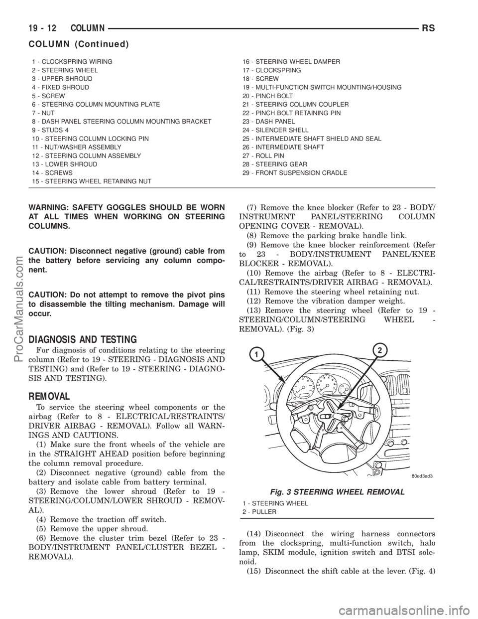
REMOVAL). (Fig. 3)
(14) Disconnect the wiring harness connectors
from the clockspring, multi-function switch, halo
lamp, SKIM module, ignition switch and BTSI sole-
noid.
(15) Disconnect the shift cable at the lever. (Fig. 4)
1 - CLOCKSPRING WIRING
2 - STEERING WHEEL
3 - UPPER SHROUD
4 - FIXED SHROUD
5 - SCREW
6 - STEERING COLUMN MOUNTING PLATE
7 - NUT
8 - DASH PANEL STEERING COLUMN MOUNTING BRACKET
9 - STUDS 4
10 - STEERING COLUMN LOCKING PIN
11 - NUT/WASHER ASSEMBLY
12 - STEERING COLUMN ASSEMBLY
13 - LOWER SHROUD
14 - SCREWS
15 - STEERING WHEEL RETAINING NUT16 - STEERING WHEEL DAMPER
17 - CLOCKSPRING
18 - SCREW
19 - MULTI-FUNCTION SWITCH MOUNTING/HOUSING
20 - PINCH BOLT
21 - STEERING COLUMN COUPLER
22 - PINCH BOLT RETAINING PIN
23 - DASH PANEL
24 - SILENCER SHELL
25 - INTERMEDIATE SHAFT SHIELD AND SEAL
26 - INTERMEDIATE SHAFT
27 - ROLL PIN
28 - STEERING GEAR
29 - FRONT SUSPENSION CRADLE
Fig. 3 STEERING WHEEL REMOVAL
1 - STEERING WHEEL
2 - PULLER
19 - 12 COLUMNRS
COLUMN (Continued)
ProCarManuals.com
Page 1471 of 2321
(16) Install the steering wheel retaining nut.
Tighten the nut to 61 N´m (45 ft. lbs.)
(17) Install the airbag (Refer to 8 - ELECTRICAL/
RESTRAINTS/DRIVER AIRBAG - INSTALLATION).
(18) Install the knee blocker reinforcement (Refer
to 23 - BODY/INSTRUMENT PANEL/KNEE
BLOCKER - INSTALLATION).
(19) Install the parking brake handle link.
(20) Install the knee blocker (Refer to 23 - BODY/
INSTRUMENT PANEL/STEERING COLUMN
OPENING COVER - INSTALLATION).
(21) Install the cluster trim bezel (Refer to 23 -
BODY/INSTRUMENT PANEL/CLUSTER BEZEL -
INSTALLATION).
(22) Install the upper shroud (Refer to 19 -
STEERING/COLUMN/LOWER SHROUD - INSTAL-
LATION).
(23) Install the traction off switch.
(24) Install the lower shroud.
SPECIFICATIONS
COLUMN TORQUE
DESCRIPTION N´mFt.
Lbs.In.
Lbs.
Steering Wheel Retaining
Nut61 45 Ð
Steering Column Mounting
Bracket Attaching Nuts12 Ð 105
Steering Column Coupling
Pinch Bolt28 Ð 250
Steering Column Airbag
Module Attaching Nuts11 Ð 100
KEY/LOCK CYLINDER
DESCRIPTION
The lock cylinder is inserted in the end of the
housing opposite the ignition switch.
OPERATION
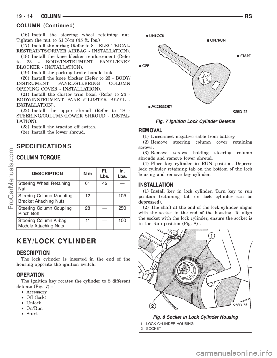
The ignition key rotates the cylinder to 5 different
detents (Fig. 7) :
²Accessory
²Off (lock)
²Unlock
²On/Run
²Start
REMOVAL
(1) Disconnect negative cable from battery.
(2) Remove steering column cover retaining
screws.
(3) Remove screws holding steering column
shrouds and remove lower shroud.
(4) Place key cylinder in RUN position. Depress
lock cylinder retaining tab on the bottom of the lock
housing and remove key cylinder.
INSTALLATION
(1) Install key in lock cylinder. Turn key to run
position (retaining tab on lock cylinder can be
depressed).
(2) The shaft at the end of the lock cylinder aligns
with the socket in the end of the housing. To align
the socket with the lock cylinder, ensure the socket is
in the Run position (Fig. 8) .
Fig. 7 Ignition Lock Cylinder Detents
Fig. 8 Socket in Lock Cylinder Housing
1 - LOCK CYLINDER HOUSING
2 - SOCKET
19 - 14 COLUMNRS
COLUMN (Continued)
ProCarManuals.com
Page 1472 of 2321
(3) Align the lock cylinder with the grooves in the
housing. Slide the lock cylinder into the housing
until the tab sticks through the opening in the hous-
ing.
(4) Turn the key to the Off position. Remove the
key.
(5) Install lower steering column shroud.
(6) Install steering column cover.
(7) Connect negative cable to battery.
GEAR SHIFT LEVER
REMOVAL
(1) Remove the knee blocker (Refer to 23 - BODY/
INSTRUMENT PANEL/STEERING COLUMN
OPENING COVER - REMOVAL).
(2) Remove the knee blocker reinforcement (Refer
to 23 - BODY/INSTRUMENT PANEL/KNEE
BLOCKER - REMOVAL).
(3) Remove the upper and lower shrouds (Refer to
19 - STEERING/COLUMN/LOWER SHROUD -
REMOVAL).
(4) Remove the cluster trim bezel (Refer to 23 -
BODY/INSTRUMENT PANEL/CLUSTER BEZEL -
REMOVAL).
(5) Remove the fixed shroud from the column.
(6) Disconnect the electrical connector to the BTSI.
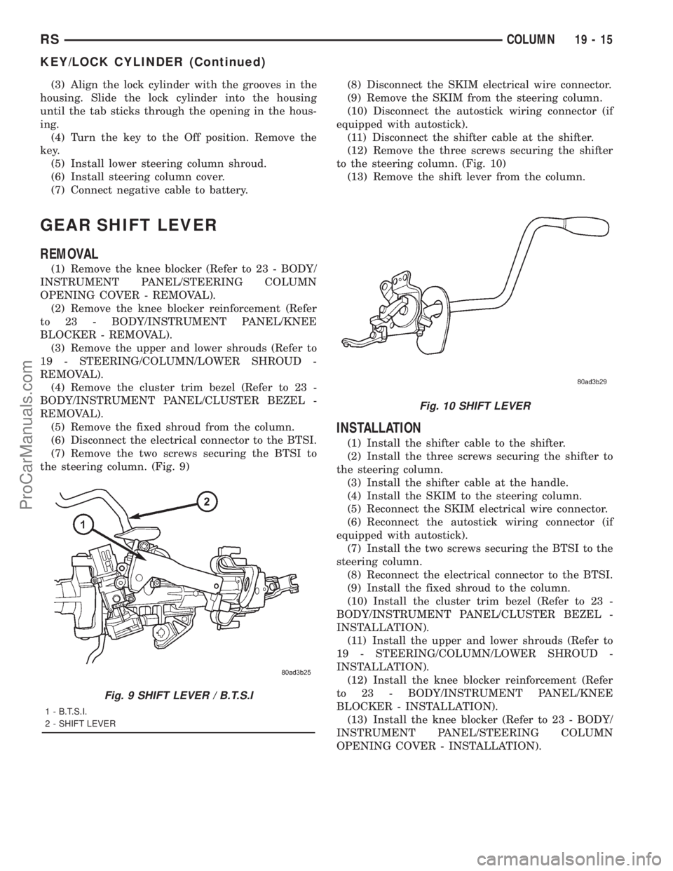
(7) Remove the two screws securing the BTSI to
the steering column. (Fig. 9)(8) Disconnect the SKIM electrical wire connector.
(9) Remove the SKIM from the steering column.
(10) Disconnect the autostick wiring connector (if
equipped with autostick).
(11) Disconnect the shifter cable at the shifter.
(12) Remove the three screws securing the shifter
to the steering column. (Fig. 10)
(13) Remove the shift lever from the column.
INSTALLATION
(1) Install the shifter cable to the shifter.
(2) Install the three screws securing the shifter to
the steering column.
(3) Install the shifter cable at the handle.
(4) Install the SKIM to the steering column.
(5) Reconnect the SKIM electrical wire connector.
(6) Reconnect the autostick wiring connector (if
equipped with autostick).
(7) Install the two screws securing the BTSI to the
steering column.
(8) Reconnect the electrical connector to the BTSI.
(9) Install the fixed shroud to the column.
(10) Install the cluster trim bezel (Refer to 23 -
BODY/INSTRUMENT PANEL/CLUSTER BEZEL -
INSTALLATION).
(11) Install the upper and lower shrouds (Refer to
19 - STEERING/COLUMN/LOWER SHROUD -
INSTALLATION).
(12) Install the knee blocker reinforcement (Refer
to 23 - BODY/INSTRUMENT PANEL/KNEE
BLOCKER - INSTALLATION).
(13) Install the knee blocker (Refer to 23 - BODY/
INSTRUMENT PANEL/STEERING COLUMN
OPENING COVER - INSTALLATION).
Fig. 9 SHIFT LEVER / B.T.S.I
1 - B.T.S.I.
2 - SHIFT LEVER
Fig. 10 SHIFT LEVER
RSCOLUMN19-15
KEY/LOCK CYLINDER (Continued)
ProCarManuals.com
Page 1597 of 2321
applied, move selector lever momentarily to each
position, ending in the park or neutral position.
(8) Check the transaxle fluid level and add an
appropriate amount to bring the transaxle fluid level
to 3mm (1/8 in.) below the ªADDº mark on the dip-
stick (Fig. 168).
(9) Recheck the fluid level after the transaxle has
reached normal operating temperature (180ÉF.).
(Refer to 21 - TRANSMISSION/TRANSAXLE/AUTO-
MATIC - 31TH/FLUID - STANDARD PROCEDURE)
(10) To prevent dirt from entering transaxle, make
certain that dipstick is fully seated into the dipstick
opening.
GEAR SHIFT CABLE
REMOVAL
(1) Disconnect battery negative cable.
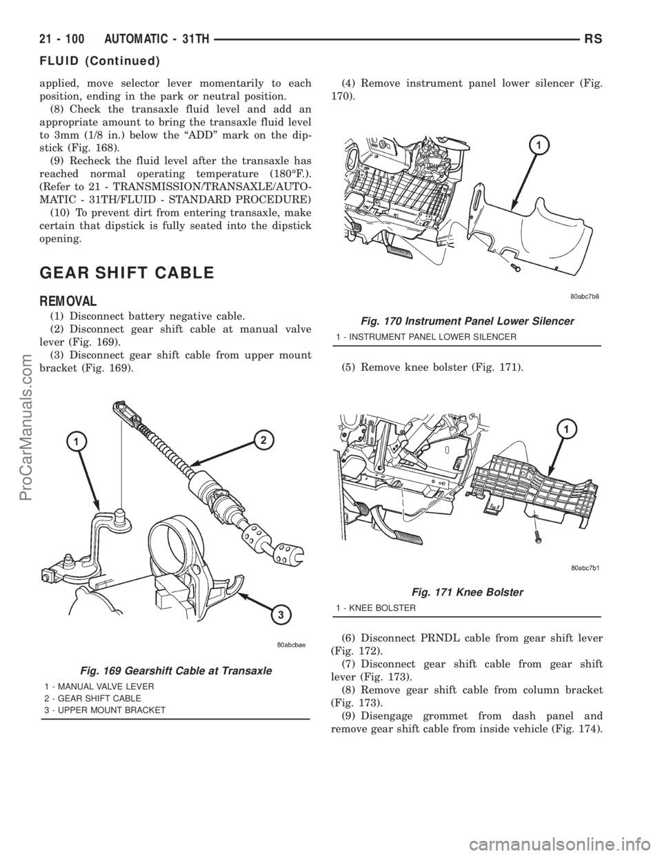
(2) Disconnect gear shift cable at manual valve
lever (Fig. 169).
(3) Disconnect gear shift cable from upper mount
bracket (Fig. 169).(4) Remove instrument panel lower silencer (Fig.
170).
(5) Remove knee bolster (Fig. 171).
(6) Disconnect PRNDL cable from gear shift lever
(Fig. 172).
(7) Disconnect gear shift cable from gear shift
lever (Fig. 173).
(8) Remove gear shift cable from column bracket
(Fig. 173).
(9) Disengage grommet from dash panel and
remove gear shift cable from inside vehicle (Fig. 174).
Fig. 169 Gearshift Cable at Transaxle
1 - MANUAL VALVE LEVER
2 - GEAR SHIFT CABLE
3 - UPPER MOUNT BRACKET
Fig. 170 Instrument Panel Lower Silencer
1 - INSTRUMENT PANEL LOWER SILENCER
Fig. 171 Knee Bolster
1 - KNEE BOLSTER
21 - 100 AUTOMATIC - 31THRS
FLUID (Continued)
ProCarManuals.com
Page 1599 of 2321
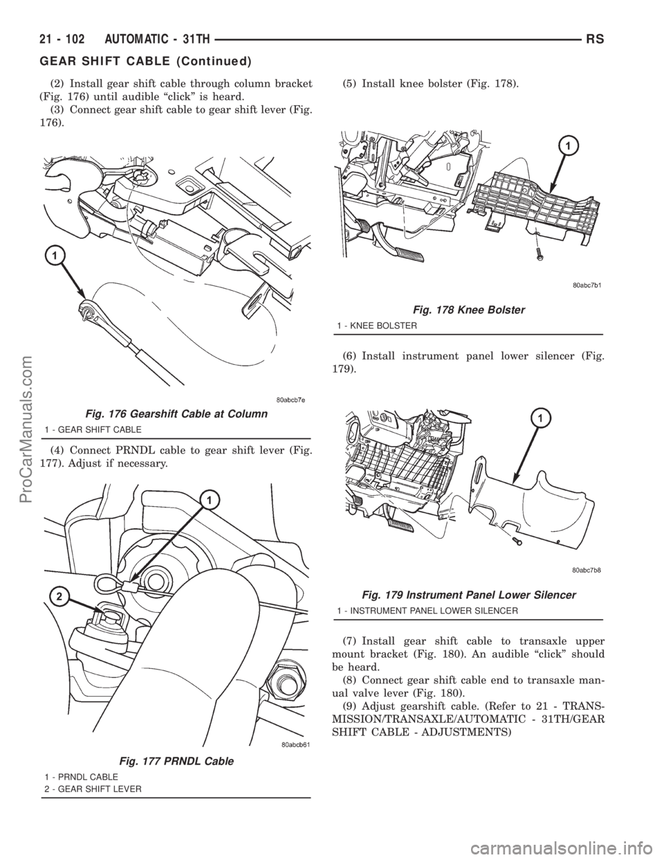
(2) Install gear shift cable through column bracket
(Fig. 176) until audible ªclickº is heard.
(3) Connect gear shift cable to gear shift lever (Fig.
176).
(4) Connect PRNDL cable to gear shift lever (Fig.
177). Adjust if necessary.(5) Install knee bolster (Fig. 178).
(6) Install instrument panel lower silencer (Fig.
179).
(7) Install gear shift cable to transaxle upper
mount bracket (Fig. 180). An audible ªclickº should
be heard.
(8) Connect gear shift cable end to transaxle man-
ual valve lever (Fig. 180).
(9) Adjust gearshift cable. (Refer to 21 - TRANS-
MISSION/TRANSAXLE/AUTOMATIC - 31TH/GEAR
SHIFT CABLE - ADJUSTMENTS)
Fig. 176 Gearshift Cable at Column
1 - GEAR SHIFT CABLE
Fig. 177 PRNDL Cable
1 - PRNDL CABLE
2 - GEAR SHIFT LEVER
Fig. 178 Knee Bolster
1 - KNEE BOLSTER
Fig. 179 Instrument Panel Lower Silencer
1 - INSTRUMENT PANEL LOWER SILENCER
21 - 102 AUTOMATIC - 31THRS
GEAR SHIFT CABLE (Continued)
ProCarManuals.com
Page 1612 of 2321
A conventional mechanical interlock system is also
used. This system manually prohibits shifter move-
ment when the ignition switch is in the LOCK or
ACC positions. Solenoid operation is not required in
these key positions. When the ignition key is in the
OFF position, the gearshift lever is unrestricted, and
able to move into any gear position (during towing,
dead battery, etc.).
For intended BTSI system operation, refer to the
following chart:
ACTION EXPECTED RESPONSE
1. Turn key to the9OFF9
position.1. Shifter CAN be shifted
out of park.
2. Turn key to the
9ON/RUN9position.2. Shifter CANNOT be
shifted out of park.
3. Turn key to the
9ON/RUN9position and
depress the brake pedal.3. Shifter CAN be shifted
out of park.
4. Leave shifter in any
gear and try to return key
to the9LOCK9or9ACC9
position.4. Key cannot be
returned to the9LOCK9or
9ACC9position.
5. Return shifter to
9PARK9and try to remove
the key.5. Key can be removed
(after returning to9LOCK9
position).
6. With the key removed,
try to shift out of9PARK9.6. Shifter cannot be
shifted out of9PARK9.
NOTE: Any failure to meet these expected
responses requires system adjustment or repair.
DIAGNOSIS AND TESTING - BRAKE/
TRANSMISSION SHIFT INTERLOCK SOLENOID
For intended BTSI system operation, refer to the
following chart:
ACTION EXPECTED RESPONSE
1. Turn key to the9OFF9
position.1. Shifter CAN be shifted
out of park.
2. Turn key to the
9ON/RUN9position.2. Shifter CANNOT be
shifted out of park.
3. Turn key to the
9ON/RUN9position and
depress the brake pedal.3. Shifter CAN be shifted
out of park.
4. Leave shifter in any
gear and try to return key
to the9LOCK9or9ACC9
position.4. Key cannot be
returned to the9LOCK9or
9ACC9position.
5. Return shifter to
9PARK9and try to remove
the key.5. Key can be removed
(after returning to9LOCK9
position).
6. With the key removed,
try to shift out of9PARK9.6. Shifter cannot be
shifted out of9PARK9.
NOTE: Any failure to meet these expected
responses requires system repair. Refer to the
appropriate Diagnostic Information.
REMOVAL
(1) Disconnect battery negative cable.
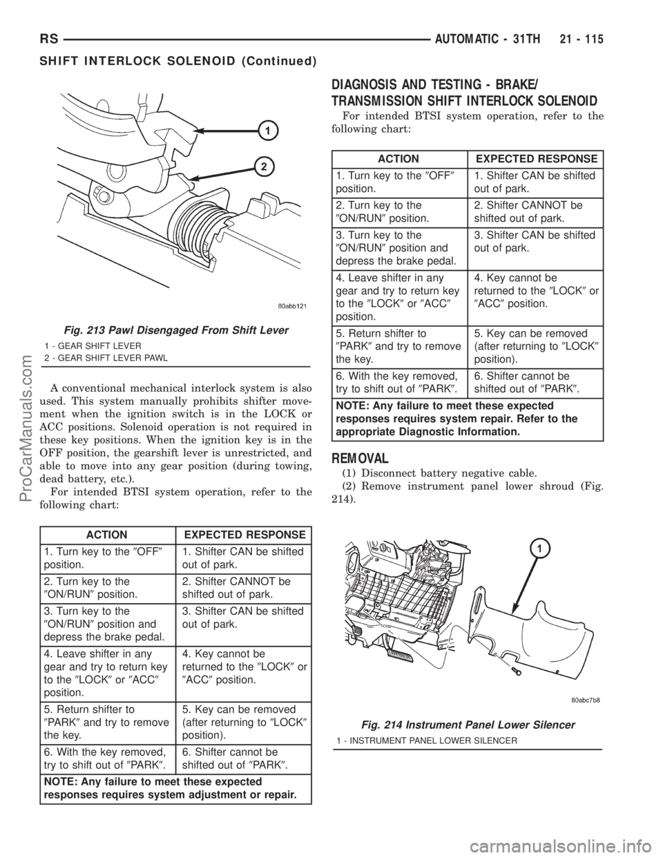
(2) Remove instrument panel lower shroud (Fig.
214).
Fig. 213 Pawl Disengaged From Shift Lever
1 - GEAR SHIFT LEVER
2 - GEAR SHIFT LEVER PAWL
Fig. 214 Instrument Panel Lower Silencer
1 - INSTRUMENT PANEL LOWER SILENCER
RSAUTOMATIC - 31TH21 - 115
SHIFT INTERLOCK SOLENOID (Continued)
ProCarManuals.com
Page 1614 of 2321
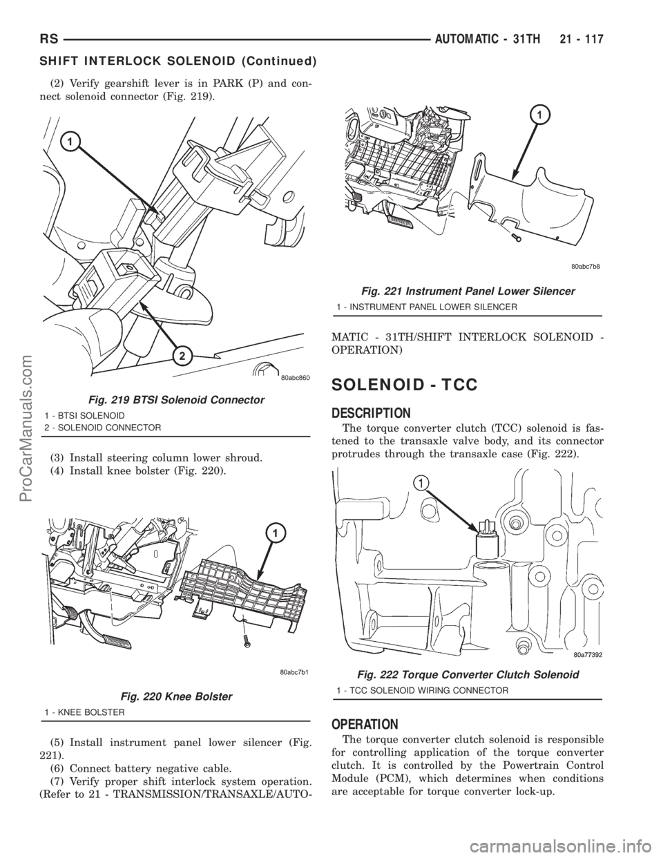
(2) Verify gearshift lever is in PARK (P) and con-
nect solenoid connector (Fig. 219).
(3) Install steering column lower shroud.
(4) Install knee bolster (Fig. 220).
(5) Install instrument panel lower silencer (Fig.
221).
(6) Connect battery negative cable.
(7) Verify proper shift interlock system operation.
(Refer to 21 - TRANSMISSION/TRANSAXLE/AUTO-MATIC - 31TH/SHIFT INTERLOCK SOLENOID -
OPERATION)
SOLENOID - TCC
DESCRIPTION
The torque converter clutch (TCC) solenoid is fas-
tened to the transaxle valve body, and its connector
protrudes through the transaxle case (Fig. 222).
OPERATION
The torque converter clutch solenoid is responsible
for controlling application of the torque converter
clutch. It is controlled by the Powertrain Control
Module (PCM), which determines when conditions
are acceptable for torque converter lock-up.
Fig. 219 BTSI Solenoid Connector
1 - BTSI SOLENOID
2 - SOLENOID CONNECTOR
Fig. 220 Knee Bolster
1 - KNEE BOLSTER
Fig. 221 Instrument Panel Lower Silencer
1 - INSTRUMENT PANEL LOWER SILENCER
Fig. 222 Torque Converter Clutch Solenoid
1 - TCC SOLENOID WIRING CONNECTOR
RSAUTOMATIC - 31TH21 - 117
SHIFT INTERLOCK SOLENOID (Continued)
ProCarManuals.com
Page 1746 of 2321
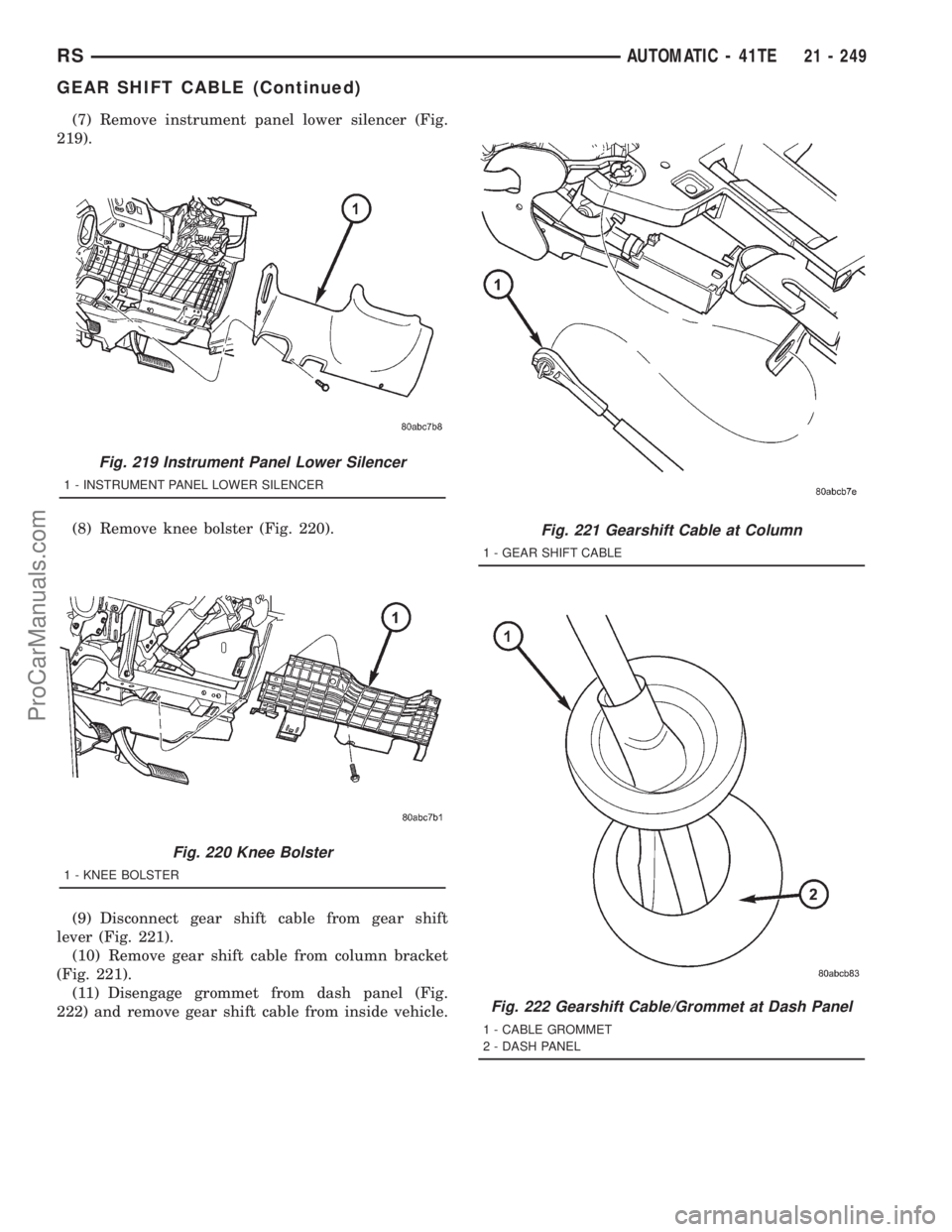
(7) Remove instrument panel lower silencer (Fig.
219).
(8) Remove knee bolster (Fig. 220).
(9) Disconnect gear shift cable from gear shift
lever (Fig. 221).
(10) Remove gear shift cable from column bracket
(Fig. 221).
(11) Disengage grommet from dash panel (Fig.
222) and remove gear shift cable from inside vehicle.
Fig. 219 Instrument Panel Lower Silencer
1 - INSTRUMENT PANEL LOWER SILENCER
Fig. 220 Knee Bolster
1 - KNEE BOLSTER
Fig. 221 Gearshift Cable at Column
1 - GEAR SHIFT CABLE
Fig. 222 Gearshift Cable/Grommet at Dash Panel
1 - CABLE GROMMET
2 - DASH PANEL
RSAUTOMATIC - 41TE21 - 249
GEAR SHIFT CABLE (Continued)
ProCarManuals.com