2001 DODGE TOWN AND COUNTRY instrument panel
[x] Cancel search: instrument panelPage 1747 of 2321
INSTALLATION
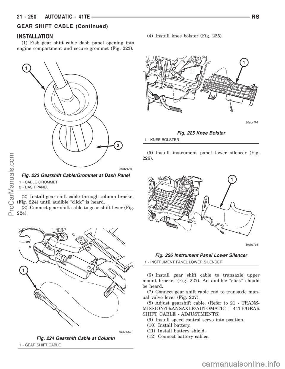
(1) Fish gear shift cable dash panel opening into
engine compartment and secure grommet (Fig. 223).
(2) Install gear shift cable through column bracket
(Fig. 224) until audible ªclickº is heard.
(3) Connect gear shift cable to gear shift lever (Fig.
224).(4) Install knee bolster (Fig. 225).
(5) Install instrument panel lower silencer (Fig.
226).
(6) Install gear shift cable to transaxle upper
mount bracket (Fig. 227). An audible ªclickº should
be heard.
(7) Connect gear shift cable end to transaxle man-
ual valve lever (Fig. 227).
(8) Adjust gearshift cable. (Refer to 21 - TRANS-
MISSION/TRANSAXLE/AUTOMATIC - 41TE/GEAR
SHIFT CABLE - ADJUSTMENTS)
(9) Install speed control servo into position.
(10) Install battery.
(11) Install battery shield.
(12) Connect battery cables.
Fig. 223 Gearshift Cable/Grommet at Dash Panel
1 - CABLE GROMMET
2 - DASH PANEL
Fig. 224 Gearshift Cable at Column
1 - GEAR SHIFT CABLE
Fig. 225 Knee Bolster
1 - KNEE BOLSTER
Fig. 226 Instrument Panel Lower Silencer
1 - INSTRUMENT PANEL LOWER SILENCER
21 - 250 AUTOMATIC - 41TERS
GEAR SHIFT CABLE (Continued)
ProCarManuals.com
Page 1771 of 2321
For intended BTSI system operation, refer to the
following chart:
ACTION EXPECTED RESPONSE
1. Turn key to the9OFF9
position.1. Shifter CAN be shifted
out of park.
2. Turn key to the
9ON/RUN9position.2. Shifter CANNOT be
shifted out of park.
3. Turn key to the
9ON/RUN9position and
depress the brake pedal.3. Shifter CAN be shifted
out of park.
4. Leave shifter in any
gear and try to return key
to the9LOCK9or9ACC9
position.4. Key cannot be
returned to the9LOCK9or
9ACC9position.
5. Return shifter to
9PARK9and try to remove
the key.5. Key can be removed
(after returning to9LOCK9
position).
6. With the key removed,
try to shift out of9PARK9.6. Shifter cannot be
shifted out of9PARK9.
NOTE: Any failure to meet these expected
responses requires system adjustment or repair.
DIAGNOSIS AND TESTING - BRAKE/
TRANSMISSION SHIFT INTERLOCK SOLENOID
For intended BTSI system operation, refer to the
following chart:
ACTION EXPECTED RESPONSE
1. Turn key to the9OFF9
position.1. Shifter CAN be shifted
out of park.
2. Turn key to the
9ON/RUN9position.2. Shifter CANNOT be
shifted out of park.
3. Turn key to the
9ON/RUN9position and
depress the brake pedal.3. Shifter CAN be shifted
out of park.
4. Leave shifter in any
gear and try to return key
to the9LOCK9or9ACC9
position.4. Key cannot be
returned to the9LOCK9or
9ACC9position.
5. Return shifter to
9PARK9and try to remove
the key.5. Key can be removed
(after returning to9LOCK9
position).
6. With the key removed,
try to shift out of9PARK9.6. Shifter cannot be
shifted out of9PARK9.
NOTE: Any failure to meet these expected
responses requires system repair. Refer to the
appropriate Diagnostic Information.
REMOVAL
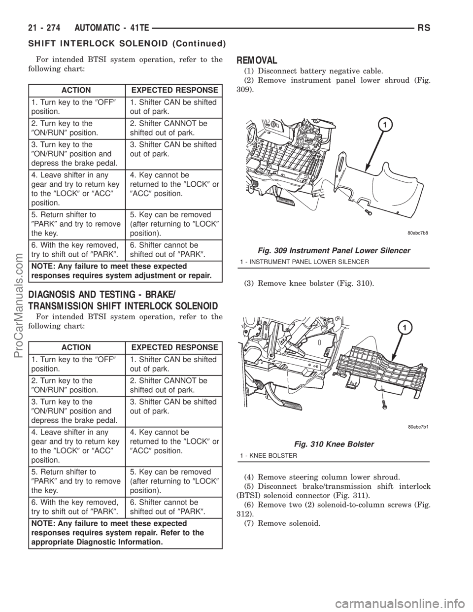
(1) Disconnect battery negative cable.
(2) Remove instrument panel lower shroud (Fig.
309).
(3) Remove knee bolster (Fig. 310).
(4) Remove steering column lower shroud.
(5) Disconnect brake/transmission shift interlock
(BTSI) solenoid connector (Fig. 311).
(6) Remove two (2) solenoid-to-column screws (Fig.
312).
(7) Remove solenoid.
Fig. 309 Instrument Panel Lower Silencer
1 - INSTRUMENT PANEL LOWER SILENCER
Fig. 310 Knee Bolster
1 - KNEE BOLSTER
21 - 274 AUTOMATIC - 41TERS
SHIFT INTERLOCK SOLENOID (Continued)
ProCarManuals.com
Page 1773 of 2321
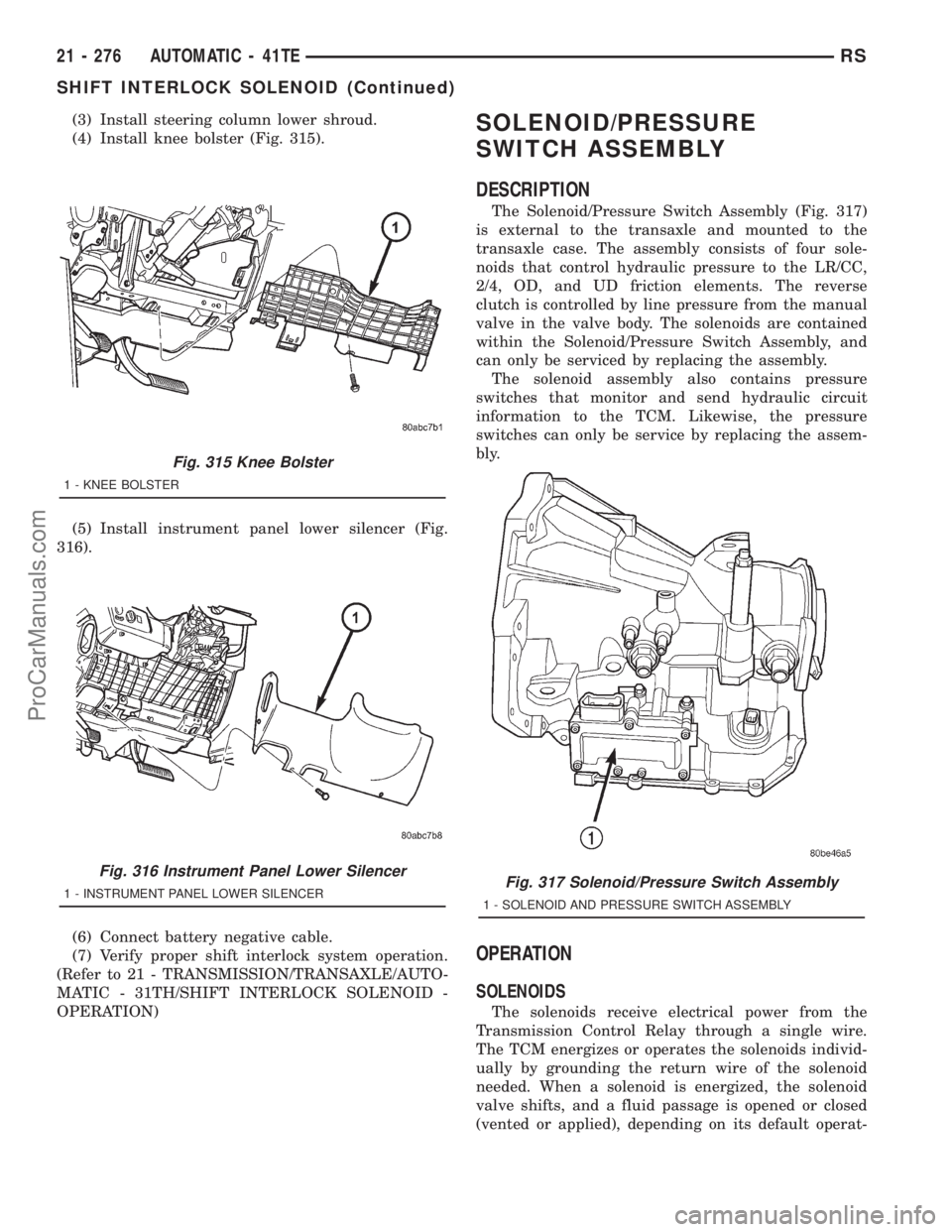
(3) Install steering column lower shroud.
(4) Install knee bolster (Fig. 315).
(5) Install instrument panel lower silencer (Fig.
316).
(6) Connect battery negative cable.
(7) Verify proper shift interlock system operation.
(Refer to 21 - TRANSMISSION/TRANSAXLE/AUTO-
MATIC - 31TH/SHIFT INTERLOCK SOLENOID -
OPERATION)SOLENOID/PRESSURE
SWITCH ASSEMBLY
DESCRIPTION
The Solenoid/Pressure Switch Assembly (Fig. 317)
is external to the transaxle and mounted to the
transaxle case. The assembly consists of four sole-
noids that control hydraulic pressure to the LR/CC,
2/4, OD, and UD friction elements. The reverse
clutch is controlled by line pressure from the manual
valve in the valve body. The solenoids are contained
within the Solenoid/Pressure Switch Assembly, and
can only be serviced by replacing the assembly.
The solenoid assembly also contains pressure
switches that monitor and send hydraulic circuit
information to the TCM. Likewise, the pressure
switches can only be service by replacing the assem-
bly.
OPERATION
SOLENOIDS
The solenoids receive electrical power from the
Transmission Control Relay through a single wire.
The TCM energizes or operates the solenoids individ-
ually by grounding the return wire of the solenoid
needed. When a solenoid is energized, the solenoid
valve shifts, and a fluid passage is opened or closed
(vented or applied), depending on its default operat-
Fig. 315 Knee Bolster
1 - KNEE BOLSTER
Fig. 316 Instrument Panel Lower Silencer
1 - INSTRUMENT PANEL LOWER SILENCERFig. 317 Solenoid/Pressure Switch Assembly
1 - SOLENOID AND PRESSURE SWITCH ASSEMBLY
21 - 276 AUTOMATIC - 41TERS
SHIFT INTERLOCK SOLENOID (Continued)
ProCarManuals.com
Page 1914 of 2321
BODY
TABLE OF CONTENTS
page page
BODY
DESCRIPTION............................1
WARNING...............................2
DIAGNOSIS AND TESTING..................2
WATER LEAKS..........................2
WIND NOISE...........................3
STANDARD PROCEDURE...................4
PLASTIC BODY PANEL REPAIR.............4
HEAT STAKING.........................8
SPECIFICATIONS.........................9
SPECIAL TOOLS........................151DOOR - FRONT.........................152
DOORS - SLIDING.......................162
DECKLID/HATCH/LIFTGATE/TAILGATE.......180
EXTERIOR.............................184
HOOD................................199
INSTRUMENT PANEL....................202
INTERIOR.............................208
PAINT................................220
SEATS................................222
STATIONARY GLASS.....................243
WEATHERSTRIP/SEALS..................248
BODY
DESCRIPTION - LOCK CYLINDERS
Ignition, door, deck lid, and rear hatch lock cylin-
ders are all codable to the key. Lock barrels, tum-
blers, and tumbler springs are available to allow the
technician to change replacement locks cylinders to
match the customer's original key set. See the appro-
priate section in this manual for lock cylinder
removal. See the Moparž catalogue for part numbers
and lock coding procedures.
DESCRIPTION - VEHICLE IDENTIFICATION
Throughout this group, references to the
DaimlerChrysler Corporation vehicle family identifi-
cation code are used when describing a procedure
that is unique to that vehicle. Refer to Introduction
Group of this manual for detailed information on
vehicle identification. If a procedure is common to all
vehicles covered in this manual, no reference will be
made to a vehicle family code.
DESCRIPTION - PUSH-IN FASTENERS
DaimlerChrysler Corporation uses many different
types of push-in fasteners to secure the interior and
exterior trim to the body. Most of these fasteners can
be reused to assemble the trim during various repair
procedures. At times, a push-in fastener cannot be
removed without damaging the fastener or the com-
ponent it is holding. If it is not possible to remove a
fastener without damaging a component or body, cut
or break the fastener and use a new one when
installing the component. Never pry or pound on a
plastic or pressed-board trim component. Using a
suitable fork-type prying device, pry the fastener
from the retaining hole behind the component beingremoved. When installing, verify fastener alignment
with the retaining hole by hand. Push directly on or
over the fastener until it seats. Apply a low-force pull
to the panel to verify that it is secure.
When it is necessary to remove components to ser-
vice another, it should not be necessary to apply
excessive force or bend a component to remove it.
Before damaging a trim component, verify hidden
fasteners or captured edges holding the component in
place.
DESCRIPTION
PAINT
The original equipment finish is a multi-step pro-
cess that involves cleaning, electrodeposition (e-coat),
base coat, and clear coat steps. Additionally, selected
areas of the vehicle may be coated with an anti-chip
finish.
On most vehicles a two-stage paint application
(base coat/clear coat) is used. Color that is applied to
primer is called base coat. The clear coat protects the
base coat from ultraviolet light and provides a dura-
ble high-gloss finish.
STATIONARY GLASS
Windshields are made of two pieces of glass with a
plastic inner layer. Windshields and selected station-
ary glass are structural members of the vehicle. The
windshield glass is bonded to the windshield frame
with urethane adhesive.
Windshields and other stationary glass protect the
occupants from the effects of the elements. Wind-
shields are also used to retain some airbags in posi-
tion during deployment. Urethane bonded glass is
difficult to salvage during removal. The urethane
bonding is difficult to cut or clean from any surface.
RSBODY23-1
ProCarManuals.com
Page 2004 of 2321
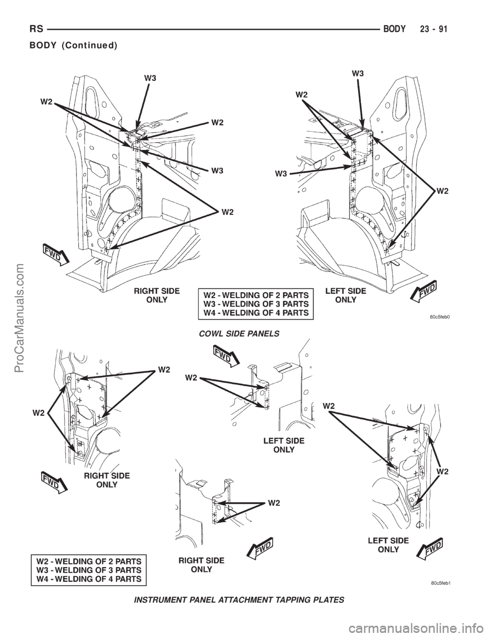
COWL SIDE PANELS
INSTRUMENT PANEL ATTACHMENT TAPPING PLATES
RSBODY23-91
BODY (Continued)
ProCarManuals.com
Page 2005 of 2321
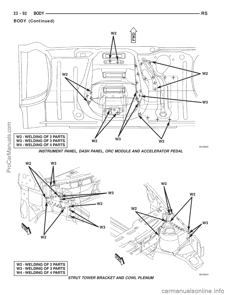
INSTRUMENT PANEL, DASH PANEL, ORC MODULE AND ACCELERATOR PEDAL
STRUT TOWER BRACKET AND COWL PLENUM
23 - 92 BODYRS
BODY (Continued)
ProCarManuals.com
Page 2114 of 2321
(4) Align hood latch by placing latch over net
pierced tabs. If alignment is required, flatten or
grind tabs.
(5) Verify hood operation and alignment. Adjust as
necessary.
(6) Tighten attaching bolts to 13.5 N´m (10 ft. lbs.)
torque.
LATCH RELEASE CABLE
REMOVAL
(1) Remove hood latch.
(2) Disengage cable end from hood latch locking
mechanism.
(3) Slide cable case end sideways in keyhole slot of
hood latch while pinching barb on cable case closed.
(4) Remove cable from latch (Fig. 4).
(5) Remove hood release handle from instrument
panel.
(6) Disengage rubber grommet cable insulator
from hole in dash panel.
(7) Attach a suitable length of mechanic's wire to
latch end of cable to assist cable installation.
(8) Route cable back from latch through engine
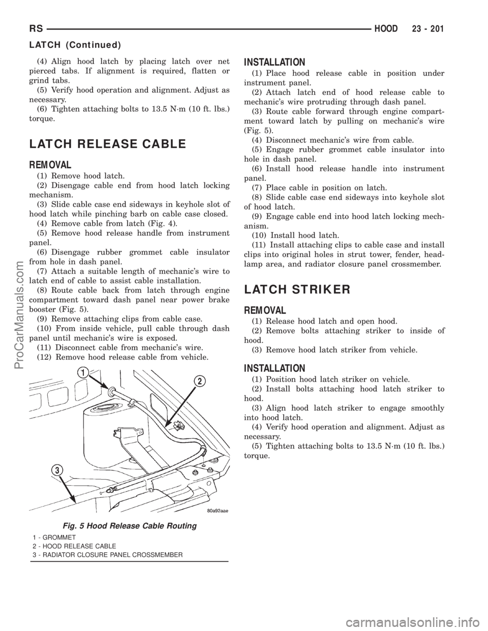
compartment toward dash panel near power brake
booster (Fig. 5).
(9) Remove attaching clips from cable case.
(10) From inside vehicle, pull cable through dash
panel until mechanic's wire is exposed.
(11) Disconnect cable from mechanic's wire.
(12) Remove hood release cable from vehicle.
INSTALLATION
(1) Place hood release cable in position under
instrument panel.
(2) Attach latch end of hood release cable to
mechanic's wire protruding through dash panel.
(3) Route cable forward through engine compart-
ment toward latch by pulling on mechanic's wire
(Fig. 5).
(4) Disconnect mechanic's wire from cable.
(5) Engage rubber grommet cable insulator into
hole in dash panel.
(6) Install hood release handle into instrument
panel.
(7) Place cable in position on latch.
(8) Slide cable case end sideways into keyhole slot
of hood latch.
(9) Engage cable end into hood latch locking mech-
anism.
(10) Install hood latch.
(11) Install attaching clips to cable case and install
clips into original holes in strut tower, fender, head-
lamp area, and radiator closure panel crossmember.
LATCH STRIKER
REMOVAL
(1) Release hood latch and open hood.
(2) Remove bolts attaching striker to inside of
hood.
(3) Remove hood latch striker from vehicle.
INSTALLATION
(1) Position hood latch striker on vehicle.
(2) Install bolts attaching hood latch striker to
hood.
(3) Align hood latch striker to engage smoothly
into hood latch.
(4) Verify hood operation and alignment. Adjust as
necessary.
(5) Tighten attaching bolts to 13.5 N´m (10 ft. lbs.)
torque.
Fig. 5 Hood Release Cable Routing
1 - GROMMET
2 - HOOD RELEASE CABLE
3 - RADIATOR CLOSURE PANEL CROSSMEMBER
RSHOOD23 - 201
LATCH (Continued)
ProCarManuals.com
Page 2115 of 2321
INSTRUMENT PANEL
TABLE OF CONTENTS
page page
CLUSTER BEZEL
REMOVAL.............................202
INSTALLATION..........................202
CUP HOLDER
REMOVAL.............................202
INSTALLATION..........................202
GLOVE BOX
REMOVAL.............................203
INSTALLATION..........................203
GLOVE BOX LATCH
REMOVAL.............................203
INSTALLATION..........................203
GLOVE BOX LATCH STRIKER
REMOVAL.............................203
INSTALLATION..........................203
INSTRUMENT PANEL ASSEMBLY
REMOVAL.............................203
INSTALLATION..........................204
INSTRUMENT PANEL CENTER BEZEL
REMOVAL.............................205
INSTALLATION..........................205INSTRUMENT PANEL END COVER
REMOVAL.............................205
INSTALLATION..........................205
INSTRUMENT PANEL TOP COVER
REMOVAL.............................205
INSTALLATION..........................206
KNEE BLOCKER REINFORCEMENT
REMOVAL.............................206
INSTALLATION..........................206
LOWER CONSOLE
REMOVAL.............................206
INSTALLATION..........................206
LOWER INSTRUMENT PANEL
REMOVAL.............................206
INSTALLATION..........................206
LOWER STEERING COLUMN COVER
REMOVAL.............................206
INSTALLATION..........................206
OVER STEERING COLUMN COVER
REMOVAL.............................207
INSTALLATION..........................207
CLUSTER BEZEL
REMOVAL
(1) Disconnect and isolate the battery negative
cable.
(2) Remove Over Steering Column Bezel by lifting
it straight up with a firm pull.
(3) Remove the four bezel attaching screws.
(4) Tilt the steering column in the full down posi-
tion.
(5) Pull rearward on the cluster bezel and remove.
INSTALLATION
(1) Manuever cluster bezel over steering column
and into position.
(2) Install the four bezel attaching screws.
(3) Install the Over Steering Column Bezel by
positioning it over the retaining slots and firmly
snapping it into place.
(4) Connect the battery negative cable.
CUP HOLDER
REMOVAL
(1) Remove the cup holder. Pull the cup holder out
and depress the tang in the middle back and pull
rearward to release the cup holder.
(2) Remove the screw access cover from the bottom
of the center bezel.
(3) Using a trim stick (special tool #C-4755) or
equivalent, gently pry out on the edge of the instru-
ment panel center bezel. Hang off to the side leaving
the accessory switches connected.
(4) Remove the cup holder assembly attaching
screws and pull the assembly rearward to disengage
the rear guide studs from instrument panel.
(5) Remove the cup holder track assembly.
INSTALLATION
(1) Install the cup holder track assembly.
(2) Place the cup holder track assembly into posi-
tion and slide into opening in instrument panel until
the rear guide struts snap into place. Install the cup
holder assembly attaching screws.
(3) Install the center bezel.
(4) Install the screw access cover from the bottom
of the center bezel.
23 - 202 INSTRUMENT PANELRS
ProCarManuals.com