2001 DODGE TOWN AND COUNTRY engine coolant
[x] Cancel search: engine coolantPage 1215 of 2321
(9) Connect vacuum lines for power brake booster,
LDP, EGR transducer, and speed control vacuum res-
ervoir (if equipped) at upper intake manifold fittings.
(10) Connect vacuum lines for purge solenoid and
PCV valve.
(11) Connect electrical connectors for MAP sensor,
throttle position sensor (TPS), and idle air control
(IAC) motor.
(12) Install air cleaner upper housing and air
intake tube to throttle body.
(13) Connect inlet air temperature sensor connec-
tor (Fig. 104).
(14) Connect negative cable to battery.
INTAKE MANIFOLD - LOWER
REMOVAL
(1) Perform fuel system pressure release proce-
durebefore attempting any repairs.(Refer to 14 -
FUEL SYSTEM/FUEL DELIVERY - STANDARD
PROCEDURE)
(2) Remove upper intake manifold. (Refer to 9 -
ENGINE/MANIFOLDS/INTAKE MANIFOLD -
REMOVAL)
CAUTION: Cover intake manifold openings to pre-
vent foreign material from entering engine.
(3) Disconnect fuel line. (Refer to 14 - FUEL SYS-
TEM/FUEL DELIVERY/QUICK CONNECT FIT-
TING - STANDARD PROCEDURE)
(4) Drain the cooling system. (Refer to 7 - COOL-
ING - STANDARD PROCEDURE)
(5) Remove heater supply and radiator upper
hoses at intake manifold.
(6) Disconnect coolant temperature sensor/fuel
injector wire harness connector.
(7) Remove lower intake manifold support bracket
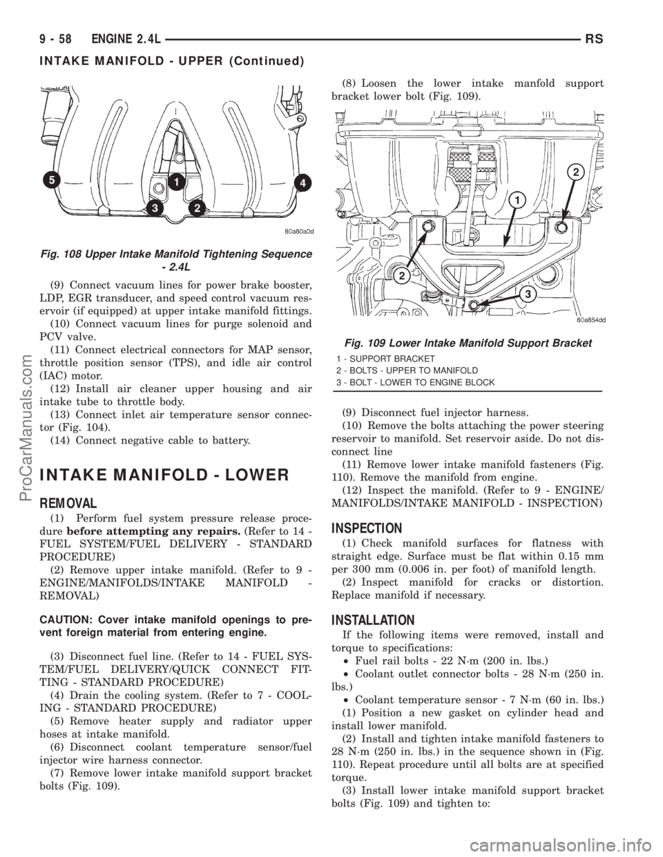
bolts (Fig. 109).(8) Loosen the lower intake manfold support
bracket lower bolt (Fig. 109).
(9) Disconnect fuel injector harness.
(10) Remove the bolts attaching the power steering
reservoir to manifold. Set reservoir aside. Do not dis-
connect line
(11) Remove lower intake manifold fasteners (Fig.
110). Remove the manifold from engine.
(12) Inspect the manifold. (Refer to 9 - ENGINE/
MANIFOLDS/INTAKE MANIFOLD - INSPECTION)
INSPECTION
(1) Check manifold surfaces for flatness with
straight edge. Surface must be flat within 0.15 mm
per 300 mm (0.006 in. per foot) of manifold length.
(2) Inspect manifold for cracks or distortion.
Replace manifold if necessary.
INSTALLATION
If the following items were removed, install and
torque to specifications:
²Fuel rail bolts - 22 N´m (200 in. lbs.)
²Coolant outlet connector bolts - 28 N´m (250 in.
lbs.)
²Coolant temperature sensor - 7 N´m (60 in. lbs.)
(1) Position a new gasket on cylinder head and
install lower manifold.
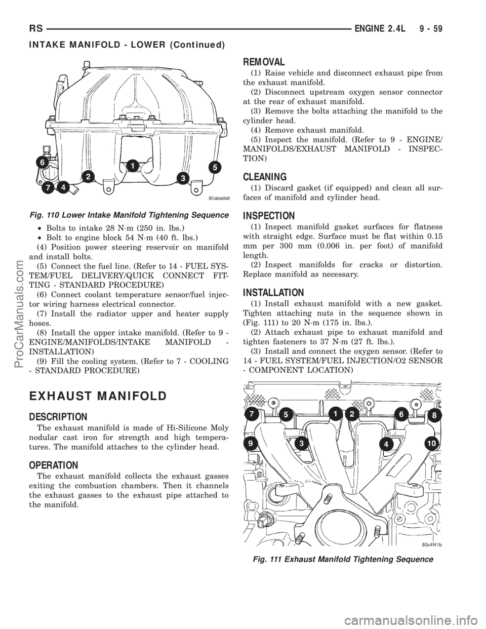
(2) Install and tighten intake manifold fasteners to
28 N´m (250 in. lbs.) in the sequence shown in (Fig.
110). Repeat procedure until all bolts are at specified
torque.
(3) Install lower intake manifold support bracket
bolts (Fig. 109) and tighten to:
Fig. 108 Upper Intake Manifold Tightening Sequence
- 2.4L
Fig. 109 Lower Intake Manifold Support Bracket
1 - SUPPORT BRACKET
2 - BOLTS - UPPER TO MANIFOLD
3 - BOLT - LOWER TO ENGINE BLOCK
9 - 58 ENGINE 2.4LRS
INTAKE MANIFOLD - UPPER (Continued)
ProCarManuals.com
Page 1216 of 2321
²Bolts to intake 28 N´m (250 in. lbs.)
²Bolt to engine block 54 N´m (40 ft. lbs.)
(4) Position power steering reservoir on manifold
and install bolts.
(5) Connect the fuel line. (Refer to 14 - FUEL SYS-
TEM/FUEL DELIVERY/QUICK CONNECT FIT-
TING - STANDARD PROCEDURE)
(6) Connect coolant temperature sensor/fuel injec-
tor wiring harness electrical connector.
(7) Install the radiator upper and heater supply
hoses.
(8) Install the upper intake manifold. (Refer to 9 -
ENGINE/MANIFOLDS/INTAKE MANIFOLD -
INSTALLATION)
(9) Fill the cooling system. (Refer to 7 - COOLING
- STANDARD PROCEDURE)
EXHAUST MANIFOLD
DESCRIPTION
The exhaust manifold is made of Hi-Silicone Moly
nodular cast iron for strength and high tempera-
tures. The manifold attaches to the cylinder head.
OPERATION
The exhaust manifold collects the exhaust gasses
exiting the combustion chambers. Then it channels
the exhaust gasses to the exhaust pipe attached to
the manifold.
REMOVAL
(1) Raise vehicle and disconnect exhaust pipe from
the exhaust manifold.
(2) Disconnect upstream oxygen sensor connector
at the rear of exhaust manifold.
(3) Remove the bolts attaching the manifold to the
cylinder head.
(4) Remove exhaust manifold.
(5) Inspect the manifold. (Refer to 9 - ENGINE/
MANIFOLDS/EXHAUST MANIFOLD - INSPEC-
TION)
CLEANING
(1) Discard gasket (if equipped) and clean all sur-
faces of manifold and cylinder head.
INSPECTION
(1) Inspect manifold gasket surfaces for flatness
with straight edge. Surface must be flat within 0.15
mm per 300 mm (0.006 in. per foot) of manifold
length.
(2) Inspect manifolds for cracks or distortion.
Replace manifold as necessary.
INSTALLATION
(1) Install exhaust manifold with a new gasket.
Tighten attaching nuts in the sequence shown in
(Fig. 111) to 20 N´m (175 in. lbs.).
(2) Attach exhaust pipe to exhaust manifold and
tighten fasteners to 37 N´m (27 ft. lbs.).
(3) Install and connect the oxygen sensor. (Refer to
14 - FUEL SYSTEM/FUEL INJECTION/O2 SENSOR
- COMPONENT LOCATION)
Fig. 110 Lower Intake Manifold Tightening Sequence
Fig. 111 Exhaust Manifold Tightening Sequence
RSENGINE 2.4L9-59
INTAKE MANIFOLD - LOWER (Continued)
ProCarManuals.com
Page 1219 of 2321
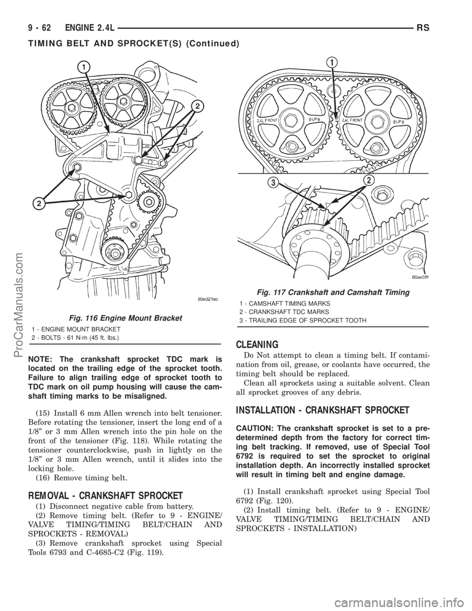
NOTE: The crankshaft sprocket TDC mark is
located on the trailing edge of the sprocket tooth.
Failure to align trailing edge of sprocket tooth to
TDC mark on oil pump housing will cause the cam-
shaft timing marks to be misaligned.
(15) Install 6 mm Allen wrench into belt tensioner.
Before rotating the tensioner, insert the long end of a
1/8º or 3 mm Allen wrench into the pin hole on the
front of the tensioner (Fig. 118). While rotating the
tensioner counterclockwise, push in lightly on the
1/8º or 3 mm Allen wrench, until it slides into the
locking hole.
(16) Remove timing belt.
REMOVAL - CRANKSHAFT SPROCKET
(1) Disconnect negative cable from battery.
(2) Remove timing belt. (Refer to 9 - ENGINE/
VALVE TIMING/TIMING BELT/CHAIN AND
SPROCKETS - REMOVAL)
(3) Remove crankshaft sprocket using Special
Tools 6793 and C-4685-C2 (Fig. 119).
CLEANING
Do Not attempt to clean a timing belt. If contami-
nation from oil, grease, or coolants have occurred, the
timing belt should be replaced.
Clean all sprockets using a suitable solvent. Clean
all sprocket grooves of any debris.
INSTALLATION - CRANKSHAFT SPROCKET
CAUTION: The crankshaft sprocket is set to a pre-
determined depth from the factory for correct tim-
ing belt tracking. If removed, use of Special Tool
6792 is required to set the sprocket to original
installation depth. An incorrectly installed sprocket
will result in timing belt and engine damage.
(1) Install crankshaft sprocket using Special Tool
6792 (Fig. 120).
(2) Install timing belt. (Refer to 9 - ENGINE/
VALVE TIMING/TIMING BELT/CHAIN AND
SPROCKETS - INSTALLATION)
Fig. 116 Engine Mount Bracket
1 - ENGINE MOUNT BRACKET
2 - BOLTS - 61 N´m (45 ft. lbs.)
Fig. 117 Crankshaft and Camshaft Timing
1 - CAMSHAFT TIMING MARKS
2 - CRANKSHAFT TDC MARKS
3 - TRAILING EDGE OF SPROCKET TOOTH
9 - 62 ENGINE 2.4LRS
TIMING BELT AND SPROCKET(S) (Continued)
ProCarManuals.com
Page 1236 of 2321
the cylinder in question.The recommended com-
pression pressures are to be used only as a
guide to diagnosing engine problems. An engine
should not be disassembled to determine the
cause of low compression unless some malfunc-
tion is present.
DIAGNOSIS AND TESTING - CYLINDER
COMBUSTION PRESSURE LEAKAGE
The combustion pressure leakage test provides an
accurate means for determining engine condition.
Combustion pressure leakage testing will detect:
²Exhaust and intake valve leaks (improper seat-
ing).
²Leaks between adjacent cylinders or into water
jacket.
²Any causes for combustion/compression pressure
loss.
WARNING: DO NOT REMOVE THE RADIATOR CAP
WITH THE SYSTEM HOT AND UNDER PRESSURE
BECAUSE SERIOUS BURNS FROM COOLANT CAN
OCCUR.
Check the coolant level and fill as required. DO
NOT install the radiator cap.
Start and operate the engine until it attains nor-
mal operating temperature, then turn the engine
OFF.
Clean spark plug recesses with compressed air.
Remove the spark plugs.
Remove the oil filler cap.
Remove the air cleaner.
Calibrate the tester according to the manufactur-
er's instructions. The shop air source for testing
should maintain 483 kPa (70 psi) minimum, 1,379
kPa (200 psi) maximum, with 552 kPa (80 psi) rec-
ommended.
Perform the test procedures on each cylinder
according to the tester manufacturer's instructions.
While testing, listen for pressurized air escaping
through the throttle body, tailpipe and oil filler cap
opening. Check for bubbles in the radiator coolant.
All gauge pressure indications should be equal,
with no more than 25% leakage per cylinder.
FOR EXAMPLE:At 552 kPa (80 psi) input pres-
sure, a minimum of 414 kPa (60 psi) should be main-
tained in the cylinder.
STANDARD PROCEDURE - MEASURING
BEARING CLEARANCE USING PLASTIGAGE
Engine crankshaft bearing clearances can be deter-
mined by use of Plastigage or equivalent. The follow-
ing is the recommended procedure for the use of
Plastigage:(1) Remove oil film from surface to be checked.
Plastigage is soluble in oil.
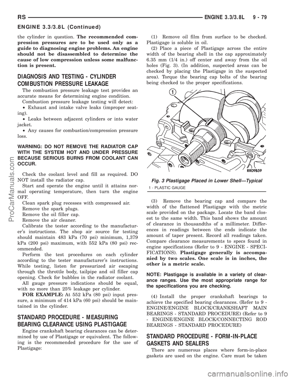
(2) Place a piece of Plastigage across the entire
width of the bearing shell in the cap approximately
6.35 mm (1/4 in.) off center and away from the oil
holes (Fig. 3). (In addition, suspected areas can be
checked by placing the Plastigage in the suspected
area). Torque the bearing cap bolts of the bearing
being checked to the proper specifications.
(3) Remove the bearing cap and compare the
width of the flattened Plastigage with the metric
scale provided on the package. Locate the band clos-
est to the same width. This band shows the amount
of clearance in thousandths of a millimeter. Differ-
ences in readings between the ends indicate the
amount of taper present. Record all readings taken.
Compare clearance measurements to specs found in
engine specifications (Refer to 9 - ENGINE - SPECI-
FICATIONS).Plastigage generally is accompa-
nied by two scales. One scale is in inches, the
other is a metric scale.
NOTE: Plastigage is available in a variety of clear-
ance ranges. Use the most appropriate range for
the specifications you are checking.
(4) Install the proper crankshaft bearings to
achieve the specified bearing clearances. (Refer to 9 -
ENGINE/ENGINE BLOCK/CRANKSHAFT MAIN
BEARINGS - STANDARD PROCEDURE) (Refer to 9
- ENGINE/ENGINE BLOCK/CONNECTING ROD
BEARINGS - STANDARD PROCEDURE)
STANDARD PROCEDURE - FORM-IN-PLACE
GASKETS AND SEALERS
There are numerous places where form-in-place
gaskets are used on the engine. Care must be taken
Fig. 3 Plastigage Placed in Lower ShellÐTypical
1 - PLASTIC GAUGE
RSENGINE 3.3/3.8L9-79
ENGINE 3.3/3.8L (Continued)
ProCarManuals.com
Page 1237 of 2321
when applying form-in-place gaskets to assure
obtaining the desired results.Do not use form-in-
place gasket material unless specified.Bead size,
continuity, and location are of great importance. Too
thin a bead can result in leakage while too much can
result in spill-over which can break off and obstruct
fluid feed lines. A continuous bead of the proper
width is essential to obtain a leak-free gasket.
There are numerous types of form-in-place gasket
materials that are used in the engine area. Mopart
Engine RTV GEN II, MopartATF-RTV, and Mopart
Gasket Maker gasket materials, each have different
properties and can not be used in place of the other.
MOPARtENGINE RTV GEN IIis used to seal
components exposed to engine oil. This material is a
specially designed black silicone rubber RTV that
retains adhesion and sealing properties when
exposed to engine oil. Moisture in the air causes the
material to cure. This material is available in three
ounce tubes and has a shelf life of one year. After one
year this material will not properly cure. Always
inspect the package for the expiration date before
use.
MOPARtATF RTVis a specifically designed
black silicone rubber RTV that retains adhesion and
sealing properties to seal components exposed to
automatic transmission fluid, engine coolants, and
moisture. This material is available in three ounce
tubes and has a shelf life of one year. After one year
this material will not properly cure. Always inspect
the package for the expiration date before use.
MOPARtGASKET MAKERis an anaerobic type
gasket material. The material cures in the absence of
air when squeezed between two metallic surfaces. It
will not cure if left in the uncovered tube. The
anaerobic material is for use between two machined
surfaces. Do not use on flexible metal flanges.
MOPARtBED PLATE SEALANTis a unique
(green-in-color) anaerobic type gasket material that
is specially made to seal the area between the bed-
plate and cylinder block without disturbing the bear-
ing clearance or alignment of these components. The
material cures slowly in the absence of air when
torqued between two metallic surfaces, and will rap-
idly cure when heat is applied.
MOPARtGASKET SEALANTis a slow drying,
permanently soft sealer. This material is recom-
mended for sealing threaded fittings and gaskets
against leakage of oil and coolant. Can be used on
threaded and machined parts under all tempera-
tures. This material is used on engines with multi-
layer steel (MLS) cylinder head gaskets. This
material also will prevent corrosion. MopartGasket
Sealant is available in a 13 oz. aerosol can or 4oz./16
oz. can w/applicator.SEALER APPLICATION
MopartGasket Maker material should be applied
sparingly 1 mm (0.040 in.) diameter or less of sealant
to one gasket surface. Be certain the material sur-
rounds each mounting hole. Excess material can eas-
ily be wiped off. Components should be torqued in
place within 15 minutes. The use of a locating dowel
is recommended during assembly to prevent smear-
ing material off the location.
MopartEngine RTV GEN II or ATF RTV gasket
material should be applied in a continuous bead
approximately 3 mm (0.120 in.) in diameter. All
mounting holes must be circled. For corner sealing, a
3.17 or 6.35 mm (1/8 or 1/4 in.) drop is placed in the
center of the gasket contact area. Uncured sealant
may be removed with a shop towel. Components
should be torqued in place while the sealant is still
wet to the touch (within 10 minutes). The usage of a
locating dowel is recommended during assembly to
prevent smearing material off the location.
MopartGasket Sealant in an aerosol can should be
applied using a thin, even coat sprayed completely
over both surfaces to be joined, and both sides of a
gasket. Then proceed with assembly. Material in a
can w/applicator can be brushed on evenly over the
sealing surfaces. Material in an aerosol can should be
used on engines with multi-layer steel gaskets.
STANDARD PROCEDURES - ENGINE GASKET
SURFACE PREPARATION
To ensure engine gasket sealing, proper surface
preparation must be performed, especially with the
use of aluminum engine components and multi-layer
steel cylinder head gaskets.
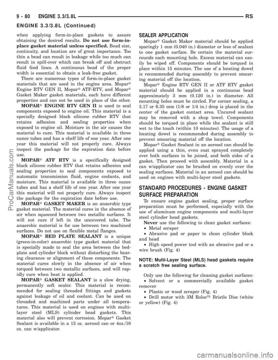
Neveruse the following to clean gasket surfaces:
²Metal scraper
²Abrasive pad or paper to clean cylinder block
and head
²High speed power tool with an abrasive pad or a
wire brush (Fig. 4)
NOTE: Multi-Layer Steel (MLS) head gaskets require
a scratch free sealing surface.
Only use the following for cleaning gasket surfaces:
²Solvent or a commercially available gasket
remover
²Plastic or wood scraper (Fig. 4)
²Drill motor with 3M RolocyBristle Disc (white
or yellow) (Fig. 4)
9 - 80 ENGINE 3.3/3.8LRS
ENGINE 3.3/3.8L (Continued)
ProCarManuals.com
Page 1239 of 2321
REMOVAL - ENGINE ASSEMBLY
(1) Perform fuel pressure release procedure. (Refer
to 14 - FUEL SYSTEM/FUEL DELIVERY - STAN-
DARD PROCEDURE)
(2) Disconnect the battery.
(3) Remove air cleaner and hoses.
(4) Disconnect the fuel line from fuel rail. (Refer to
14 - FUEL SYSTEM/FUEL DELIVERY/QUICK
CONNECT FITTING - STANDARD PROCEDURE)
(5) Remove the wiper module. (Refer to 8 - ELEC-
TRICAL/WIPERS/WASHERS/WIPER MODULE -
REMOVAL)
(6) Block off heater hoses to the rear heater sys-
tem, if equipped, using pinch-off pliers.
(7) Drain the cooling system. (Refer to 7 - COOL-
ING - STANDARD PROCEDURE)
(8) Disconnect the heater hoses.
(9) Remove the radiator upper support crossmem-
ber. (Refer to 23 - BODY/EXTERIOR/GRILLE OPEN-
ING REINFORCEMENT - REMOVAL)
(10) Remove the radiator fans. (Refer to 7 - COOL-
ING/ENGINE/RADIATOR FAN - REMOVAL)
(11) Disconnect the throttle cables from the throt-
tle body.
(12) Disconnect the MAP, IAC, and TPS electrical
connectors.
(13) Disconnect the EGR transducer electrical con-
nector.
(14) Disconnect the vacuum hoses from throttle
body.
(15) Disconnect the brake booster and speed con-
trol vacuum hoses.(16) Disengage wire harness clip from the right
side engine mount.
(17) Remove the power steering reservoir from
mounting position and set aside. Do not disconnect
hose.
(18) Disconnect ground strap from rear of cylinder
head.
(19) Disconnect engine coolant temperature (ECT)
sensor and ignition coil electrical connectors.
(20) Disconnect the fuel injector electrical harness
connector and disengage clip from support bracket.
(21) Disconnect crank sensor connector.
(22) Disconnect camshaft sensor connector.
(23) Evacuate air conditioning system.
(24) Disconnect A/C compressor electrical connec-
tor.
(25) Disconnect the A/C lines from compressor.
Cover and seal all openings of hoses and compressor.
(26) Remove the radiator upper hose.
(27) Disengage electrical harness clip at transaxle
dipstick tube.
(28) Remove transaxle dipstick tube. Seal opening
using a suitable plug.
(29) Disconnect cooler hoses from transaxle.
(30) Disconnect transaxle shift linkage and electri-
cal connectors.
(31) Raise vehicle on hoist and drain the engine
oil.
(32) Remove the axle shafts. (Refer to 3 - DIFFER-
ENTIAL & DRIVELINE/HALF SHAFT - REMOVAL)
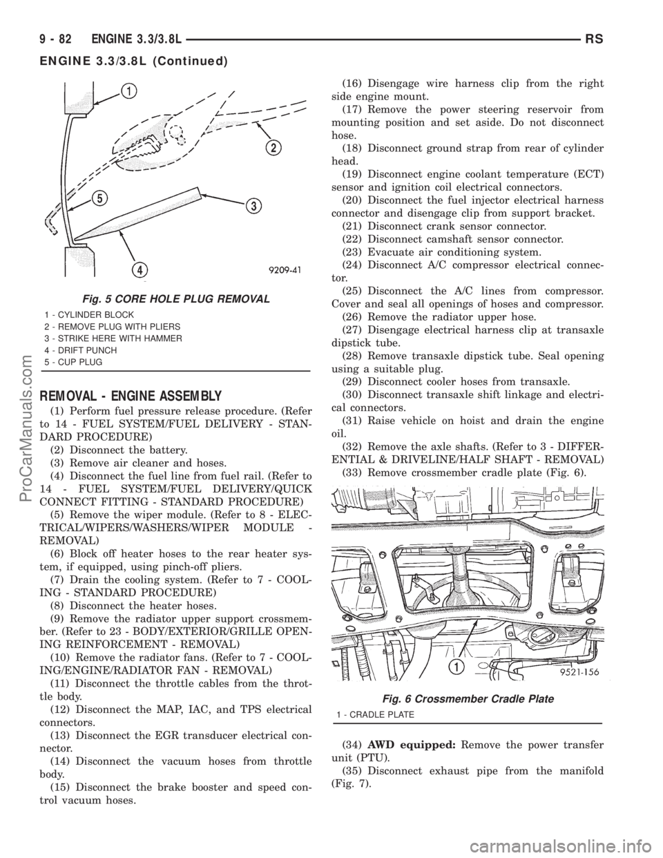
(33) Remove crossmember cradle plate (Fig. 6).
(34)AWD equipped:Remove the power transfer
unit (PTU).
(35) Disconnect exhaust pipe from the manifold
(Fig. 7).
Fig. 5 CORE HOLE PLUG REMOVAL
1 - CYLINDER BLOCK
2 - REMOVE PLUG WITH PLIERS
3 - STRIKE HERE WITH HAMMER
4 - DRIFT PUNCH
5 - CUP PLUG
Fig. 6 Crossmember Cradle Plate
1 - CRADLE PLATE
9 - 82 ENGINE 3.3/3.8LRS
ENGINE 3.3/3.8L (Continued)
ProCarManuals.com
Page 1242 of 2321
(4) Slowly raise vehicle enough to remove the
engine dolly and cradle Special Tools 6135, 6710,
6848 and 6909 (Fig. 10).
(5) Remove Special Tools 6912 and 8444.
(6) Lower the vehicle.
(7) Install power steering pump and pressure line
support.(8) Install the generator and wiring harness.
(Refer to 8 - ELECTRICAL/CHARGING/GENERA-
TOR - INSTALLATION)
(9) Raise vehicle.
(10) Attach wiring harness support clip to the dip-
stick tube.
(11) Connect oil pressure switch electrical connec-
tor.
(12) Install the A/C compressor.
(13) Install the water pump pulley.
(14) Connect the radiator lower hose.
(15) Install the accessory drive belt and splash
shield. (Refer to 7 - COOLING/ACCESSORY DRIVE/
DRIVE BELTS - INSTALLATION)
(16) Connect the engine block heater electrical con-
nector, if equipped.
(17) Connect the knock sensor electrical connector
(3.8L only).
(18) Install the torque converter to flex plate bolts.
(19) Install the transaxle case cover (Fig. 8).
(20) Install the powertrain struts (Fig. 8).
(21) Install the engine rear mount bracket.
(22) Install the engine front mount and bracket
assembly.
(23)AWD equipped;Install the power transfer
unit (PTU).
(24) Install the axle shafts. (Refer to 3 - DIFFER-
ENTIAL & DRIVELINE/HALF SHAFT - INSTALLA-
TION)
(25) Connect exhaust pipe to manifold (Fig. 7).
(26) Install crossmember cradle plate (Fig. 6).
(27) Lower vehicle.
(28) Connect transaxle shift linkage.
(29) Connect transaxle electrical connectors.
(30) Connect transaxle cooler hoses.
(31) Install transaxle dipstick tube and attach
electrical harness clip.
(32) Connect the radiator upper hose.
(33) Connect the A/C lines to compressor.
(34) Connect the A/C compressor electrical connec-
tor.
(35) Evacuate and recharge A/C system.
(36) Connect crankshaft and camshaft position
sensors.
(37) Connect the fuel injector electrical harness
connector and engage clip to support bracket.
(38) Connect engine coolant temperature (ECT)
sensor and ignition coil electrical connectors.
(39) Connect the ground strap to rear of cylinder
head.
(40) Install power steering reservoir.
(41) Engage wire harness clip to engine right side
mount.
(42) Connect the brake booster and speed control
vacuum hoses.
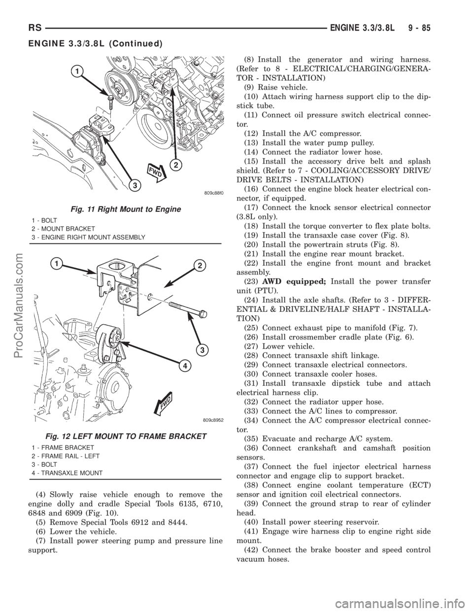
Fig. 11 Right Mount to Engine
1 - BOLT
2 - MOUNT BRACKET
3 - ENGINE RIGHT MOUNT ASSEMBLY
Fig. 12 LEFT MOUNT TO FRAME BRACKET
1 - FRAME BRACKET
2 - FRAME RAIL - LEFT
3 - BOLT
4 - TRANSAXLE MOUNT
RSENGINE 3.3/3.8L9-85
ENGINE 3.3/3.8L (Continued)
ProCarManuals.com
Page 1251 of 2321
CYLINDER HEAD
DESCRIPTION
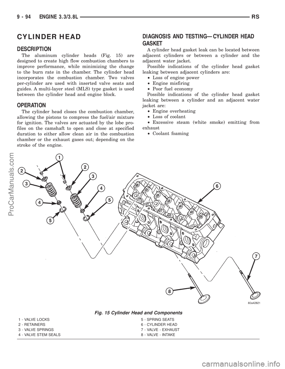
The aluminum cylinder heads (Fig. 15) are
designed to create high flow combustion chambers to
improve performance, while minimizing the change
to the burn rate in the chamber. The cylinder head
incorporates the combustion chamber. Two valves
per-cylinder are used with inserted valve seats and
guides. A multi-layer steel (MLS) type gasket is used
between the cylinder head and engine block.
OPERATION
The cylinder head closes the combustion chamber,
allowing the pistons to compress the fuel/air mixture
for ignition. The valves are actuated by the lobe pro-
files on the camshaft to open and close at specified
duration to either allow clean air in the combustion
chamber or the exhaust gases out; depending on the
stroke of the engine.
DIAGNOSIS AND TESTINGÐCYLINDER HEAD
GASKET
A cylinder head gasket leak can be located between
adjacent cylinders or between a cylinder and the
adjacent water jacket.
Possible indications of the cylinder head gasket
leaking between adjacent cylinders are:
²Loss of engine power
²Engine misfiring
²Poor fuel economy
Possible indications of the cylinder head gasket
leaking between a cylinder and an adjacent water
jacket are:
²Engine overheating
²Loss of coolant
²Excessive steam (white smoke) emitting from
exhaust
²Coolant foaming
Fig. 15 Cylinder Head and Components
1 - VALVE LOCKS 5 - SPRING SEATS
2 - RETAINERS 6 - CYLINDER HEAD
3 - VALVE SPRINGS 7 - VALVE - EXHAUST
4 - VALVE STEM SEALS 8 - VALVE - INTAKE
9 - 94 ENGINE 3.3/3.8LRS
ProCarManuals.com