2001 DODGE TOWN AND COUNTRY engine coolant
[x] Cancel search: engine coolantPage 331 of 2321

RADIATOR PRESSURE CAP
DESCRIPTION
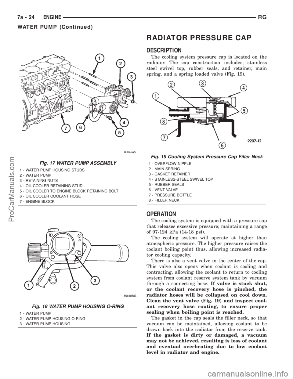
The cooling system pressure cap is located on the
radiator. The cap construction includes; stainless
steel swivel top, rubber seals, and retainer, main
spring, and a spring loaded valve (Fig. 19).
OPERATION
The cooling system is equipped with a pressure cap
that releases excessive pressure; maintaining a range
of 97-124 kPa (14-18 psi).
The cooling system will operate at higher than
atmospheric pressure. The higher pressure raises the
coolant boiling point thus, allowing increased radia-
tor cooling capacity.
There is also a vent valve in the center of the cap.
This valve also opens when coolant is cooling and
contracting, allowing the coolant to return to cooling
system from coolant reserve system tank by vacuum
through a connecting hose.If valve is stuck shut,
or the coolant recovery hose is pinched, the
radiator hoses will be collapsed on cool down.
Clean the vent valve (Fig. 19) and inspect cool-
ant recovery hose routing, to ensure proper
sealing when boiling point is reached.
The gasket in the cap seals the filler neck, so that
vacuum can be maintained, allowing coolant to be
drawn back into the radiator from the reserve tank.
If the gasket is dirty or damaged, a vacuum
may not be achieved, resulting is loss of coolant
and eventual overheating due to low coolant
level in radiator and engine.
Fig. 17 WATER PUMP ASSEMBLY
1 - WATER PUMP HOUSING STUDS
2 - WATER PUMP
3 - RETAINING NUTS
4 - OIL COOLER RETAINING STUD
5 - OIL COOLER TO ENGINE BLOCK RETAINING BOLT
6 - OIL COOLER COOLANT HOSE
7 - ENGINE BLOCK
Fig. 18 WATER PUMP HOUSING O-RING
1 - WATER PUMP
2 - WATER PUMP HOUSING O-RING
3 - WATER PUMP HOUSING
Fig. 19 Cooling System Pressure Cap Filler Neck
1 - OVERFLOW NIPPLE
2 - MAIN SPRING
3 - GASKET RETAINER
4 - STAINLESS-STEEL SWIVEL TOP
5 - RUBBER SEALS
6 - VENT VALVE
7 - PRESSURE BOTTLE
8 - FILLER NECK
7a - 24 ENGINERG
WATER PUMP (Continued)
ProCarManuals.com
Page 332 of 2321

DIAGNOSIS AND TESTING - COOLING SYSTEM
PRESSURE CAP
Dip the pressure cap in water. Clean any deposits
off the vent valve or its seat and apply cap to end of
the Pressure Cap Test Adaptor that is included with
the Cooling System Tester 7700. Working the
plunger, bring the pressure to 104 kPa (15 psi) on the
gauge. If the pressure cap fails to hold pressure of at
least 97 kPa (14 psi), replace the pressure cap.
CAUTION: The Cooling System Tester Tool is very
sensitive to small air leaks that will not cause cool-
ing system problems. A pressure cap that does not
have a history of coolant loss should not be
replaced just because it leaks slowly when tested
with this tool. Add water to the tool. Turn tool
upside down and recheck pressure cap to confirm
that cap is bad.
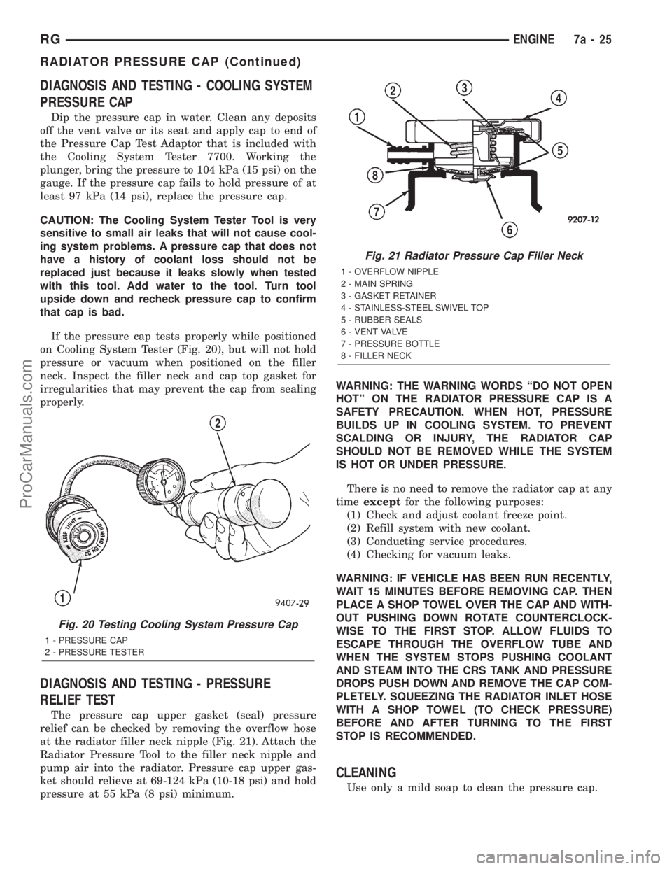
If the pressure cap tests properly while positioned
on Cooling System Tester (Fig. 20), but will not hold
pressure or vacuum when positioned on the filler
neck. Inspect the filler neck and cap top gasket for
irregularities that may prevent the cap from sealing
properly.
DIAGNOSIS AND TESTING - PRESSURE
RELIEF TEST
The pressure cap upper gasket (seal) pressure
relief can be checked by removing the overflow hose
at the radiator filler neck nipple (Fig. 21). Attach the
Radiator Pressure Tool to the filler neck nipple and
pump air into the radiator. Pressure cap upper gas-
ket should relieve at 69-124 kPa (10-18 psi) and hold
pressure at 55 kPa (8 psi) minimum.WARNING: THE WARNING WORDS ªDO NOT OPEN
HOTº ON THE RADIATOR PRESSURE CAP IS A
SAFETY PRECAUTION. WHEN HOT, PRESSURE
BUILDS UP IN COOLING SYSTEM. TO PREVENT
SCALDING OR INJURY, THE RADIATOR CAP
SHOULD NOT BE REMOVED WHILE THE SYSTEM
IS HOT OR UNDER PRESSURE.
There is no need to remove the radiator cap at any
timeexceptfor the following purposes:
(1) Check and adjust coolant freeze point.
(2) Refill system with new coolant.
(3) Conducting service procedures.
(4) Checking for vacuum leaks.
WARNING: IF VEHICLE HAS BEEN RUN RECENTLY,
WAIT 15 MINUTES BEFORE REMOVING CAP. THEN
PLACE A SHOP TOWEL OVER THE CAP AND WITH-
OUT PUSHING DOWN ROTATE COUNTERCLOCK-
WISE TO THE FIRST STOP. ALLOW FLUIDS TO
ESCAPE THROUGH THE OVERFLOW TUBE AND
WHEN THE SYSTEM STOPS PUSHING COOLANT
AND STEAM INTO THE CRS TANK AND PRESSURE
DROPS PUSH DOWN AND REMOVE THE CAP COM-
PLETELY. SQUEEZING THE RADIATOR INLET HOSE
WITH A SHOP TOWEL (TO CHECK PRESSURE)
BEFORE AND AFTER TURNING TO THE FIRST
STOP IS RECOMMENDED.
CLEANING
Use only a mild soap to clean the pressure cap.
Fig. 20 Testing Cooling System Pressure Cap
1 - PRESSURE CAP
2 - PRESSURE TESTER
Fig. 21 Radiator Pressure Cap Filler Neck
1 - OVERFLOW NIPPLE
2 - MAIN SPRING
3 - GASKET RETAINER
4 - STAINLESS-STEEL SWIVEL TOP
5 - RUBBER SEALS
6 - VENT VALVE
7 - PRESSURE BOTTLE
8 - FILLER NECK
RGENGINE7a-25
RADIATOR PRESSURE CAP (Continued)
ProCarManuals.com
Page 333 of 2321

INSPECTION
Hold the cap in your hand,top side up(Fig. 21).
The vent valve at the bottom of the cap should open.
If the rubber gasket has swollen, preventing the
valve from opening, replace the cap.
Hold the cleaned cap in your hand,upside down.
If any light can be seen between vent valve and the
rubber gasket, replace the cap.Do not use a
replacement cap that has a spring to hold the
vent shut.
A replacement cap must be of the type designed for
coolant reserve systems. This design ensures coolant
return to the radiator.
RADIATOR FAN
DESCRIPTION
The dual radiator fans are mounted to the back
side of the radiator (Fig. 22). The radiator fan consist
of the fan blade, electric motor and a support shroud
which are all serviced as an assembly.
OPERATION
RADIATOR FAN OPERATION CHART
COOLANT TEMPERATURE A/C PRESSURE
Fan Operation
Speeds:Initial Max Initial Max
Fan On: 104ÉC (220ÉF) 110ÉC (230ÉF) Fan
Speed Duty-Cycles
(Ramps-up) from
30% to 99%1,724 Kpa (250 psi) 2,068 Kpa (300 psi)
Fan Speed
Duty-Cycles
(Ramps-up) from
30% to 99%
Fan Off: 101ÉC (214ÉF) Fan Speed
Duty-Cycles
(Ramps-down) from
99% to 30%1,710 Kpa (248 psi) Fan Speed
Duty-Cycles
(Ramps-down) from
99% to 30%
DIAGNOSIS AND TESTING - RADIATOR FAN MOTOR
RADIATOR FAN DIAGNOSIS CHART
CONDITION POSSIBLE CAUSES CORRECTION
NOISY RADIATOR FAN 1. Fan blade loose. 1. Replace fan assembly. (Refer to
7 - COOLING/ENGINE/RADIATOR
FAN - REMOVAL)
2. Fan blade striking a surrounding
object.2. Locate point of fan blade contact
and repair as necessary.
3. Air obstructions at radiator or A/C
condenser.3. Remove obstructions and/or
clean debris.
4. Electric fan motor defective. 4. Replace fan assembly. (Refer to
7 - COOLING/ENGINE/RADIATOR
FAN - REMOVAL)
ELECTRIC FAN MOTOR DOES
NOT OPERATE1. Fan relay, powertrain control
module (PCM), coolant temperature
sensor, or wiring defective.1. (Refer to Appropriate Diagnostic
Information) Repair as necessary.
2. Defective A/C pressure
transducer.2. (Refer to Appropriate Diagnostic
Information) Repair as necessary.
7a - 26 ENGINERG
RADIATOR PRESSURE CAP (Continued)
ProCarManuals.com
Page 334 of 2321

CONDITION POSSIBLE CAUSES CORRECTION
ELECTRIC RADIATOR FAN
OPERATES ALL THE TIME1. Fan relay, powertrain control
module (PCM), coolant temperature
sensor or wiring defective.1. (Refer to Appropriate Diagnostic
Information) Repair as necessary.
2. Check for low coolant level. 2. Add coolant as necessary.
3. Defective A/C pressure
transducer.3. (Refer to Appropriate Diagnostic
Information) Repair as necessary.
REMOVAL
There are no repairs to be made to the fan or
shroud assembly. If the fan is warped, cracked, or
otherwise damaged, it must be replaced as an assem-
bly (Fig. 22).
(1) Remove the radiator upper crossmember. (Refer
to 23 - BODY/EXTERIOR/GRILLE OPENING REIN-
FORCEMENT - REMOVAL)
(2) Disconnect the radiator fan electrical connec-
tors.
(3) Remove radiator fan(s) retaining screw (Fig.
22).
(4) Remove the radiator fan(s) by lifting upward to
release from mounts.
INSTALLATION
(1) Install the radiator fan(s) into mounts and
attaching clips on the radiator.
(2) Install radiator fan(s) attaching screws (Fig.
22). Tighten to 5 N´m (45 in. lbs.).
(3) Connect the radiator fan(s) electrical connec-
tors.
(4) Install the radiator upper support crossmem-
ber. (Refer to 23 - BODY/EXTERIOR/GRILLE OPEN-
ING REINFORCEMENT - INSTALLATION).(5) Install the upper radiator mounts to the cross-
member bolts, if removed. Tighten to 8 N´m (70 in.
lbs.).
(6) Install the radiator upper hose to the support
clip (2.4L engine).
HOSE CLAMPS
DESCRIPTION - HOSE CLAMPS
The cooling system uses spring type hose clamps.
If a spring type clamp replacement is necessary,
replace with the original Mopartequipment spring
type clamp.
CAUTION: A number or letter is stamped into the
tongue of constant tension clamps. If replacement
is necessary, use only a original equipment clamp
with matching number or letter (Fig. 23).
Fig. 22 Radiator Fans
1 - SCREWS - RADIATOR FAN ATTACHING
2 - RADIATOR FAN - RIGHT
3 - MOUNT - RIGHT RADIATOR FAN
4 - CLIPS - RADIATOR FAN LOWER
5 - MOUNT - LEFT RADIATOR FAN
6 - RADIATOR FAN - LEFT
Fig. 23 Spring Clamp Size Location
1 - SPRING CLAMP SIZE LOCATION
RGENGINE7a-27
RADIATOR FAN (Continued)
ProCarManuals.com
Page 335 of 2321

OPERATION - HOSE CLAMPS
The spring type hose clamp applies constant ten-
sion on a hose connection. To remove a spring type
hose clamp, use Special Tool 6094 or equivalent, con-
stant tension clamp pliers (Fig. 24) to compress the
hose clamp.
RADIATOR FAN RELAY
DESCRIPTION
The low and high speed fan relays are mounted to
the upper radiator support above the charge air
cooler (Fig. 25).
OPERATION
The cooling system uses two fans. Both fans oper-
ate at two different speeds, low and high. Depending
on engine coolant temperature and A/C system high
side pressure, the fans operate at either low or high.
The ignition switch supplies voltage to the coil side of
the relay. When the ECM grounds the coil side of the
relay, the contacts close and the battery supplies
power to the fans.
COOLANT SYSTEM HOSES
REMOVAL - UPPER RADIATOR HOSE
WARNING: THE WARNING WORDS ªDO NOT OPEN
HOTº ON THE RADIATOR PRESSURE CAP IS A
SAFETY PRECAUTION. WHEN HOT, PRESSURE
BUILDS UP IN COOLING SYSTEM. TO PREVENT
SCALDING OR INJURY, THE RADIATOR CAP
SHOULD NOT BE REMOVED WHILE THE SYSTEM
IS HOT OR UNDER PRESSURE.(1) Remove engine cover (Refer to 9 - ENGINE -
REMOVAL).
(2) Drain cooling system (Refer to 7 - COOLING/
ENGINE/COOLANT - STANDARD PROCEDURE).
(3) Remove upper radiator hose (Fig. 26).
REMOVAL - LOWER RADIATOR HOSE
WARNING: THE WARNING WORDS ªDO NOT OPEN
HOTº ON THE RADIATOR PRESSURE CAP IS A
SAFETY PRECAUTION. WHEN HOT, PRESSURE
BUILDS UP IN COOLING SYSTEM. TO PREVENT
SCALDING OR INJURY, THE RADIATOR CAP
SHOULD NOT BE REMOVED WHILE THE SYSTEM
IS HOT OR UNDER PRESSURE.
(1) Drain cooling system (Refer to 7 - COOLING/
ENGINE/COOLANT - STANDARD PROCEDURE).
(2) Remove lower radiator hose (Fig. 26).
REMOVAL - COOLANT BYPASS HOSE
WARNING: THE WARNING WORDS ªDO NOT OPEN
HOTº ON THE RADIATOR PRESSURE CAP IS A
SAFETY PRECAUTION. WHEN HOT, PRESSURE
BUILDS UP IN COOLING SYSTEM. TO PREVENT
SCALDING OR INJURY, THE RADIATOR CAP
SHOULD NOT BE REMOVED WHILE THE SYSTEM
IS HOT OR UNDER PRESSURE.
(1) Drain cooling system (Refer to 7 - COOLING/
ENGINE/COOLANT - STANDARD PROCEDURE).
(2) Remove the coolant bypass hose (Fig. 26).
Fig. 24 Hose Clamp Tool
1 - HOSE CLAMP TOOL 6094
2 - HOSE CLAMP
Fig. 25 RELAY LOCATIONS
1 - GLOW PLUG RELAY
2 - UPPER RADIATOR SUPPORT
3 - CHARGE AIR COOLER OUTLET HOSE
4 - RADIATOR FAN RELAYS
5 - UPPER RADIATOR HOSE
6 - EGR SOLENOID
7a - 28 ENGINERG
HOSE CLAMPS (Continued)
ProCarManuals.com
Page 336 of 2321

INSTALLATION - UPPER RADIATOR HOSE
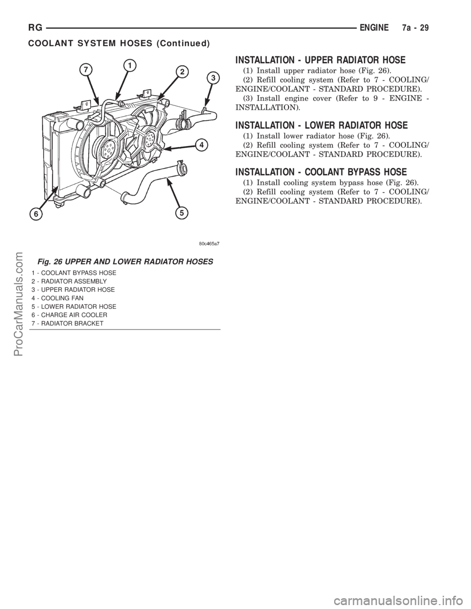
(1) Install upper radiator hose (Fig. 26).
(2) Refill cooling system (Refer to 7 - COOLING/
ENGINE/COOLANT - STANDARD PROCEDURE).
(3) Install engine cover (Refer to 9 - ENGINE -
INSTALLATION).
INSTALLATION - LOWER RADIATOR HOSE
(1) Install lower radiator hose (Fig. 26).
(2) Refill cooling system (Refer to 7 - COOLING/
ENGINE/COOLANT - STANDARD PROCEDURE).
INSTALLATION - COOLANT BYPASS HOSE
(1) Install cooling system bypass hose (Fig. 26).
(2) Refill cooling system (Refer to 7 - COOLING/
ENGINE/COOLANT - STANDARD PROCEDURE).
Fig. 26 UPPER AND LOWER RADIATOR HOSES
1 - COOLANT BYPASS HOSE
2 - RADIATOR ASSEMBLY
3 - UPPER RADIATOR HOSE
4 - COOLING FAN
5 - LOWER RADIATOR HOSE
6 - CHARGE AIR COOLER
7 - RADIATOR BRACKET
RGENGINE7a-29
COOLANT SYSTEM HOSES (Continued)
ProCarManuals.com
Page 353 of 2321

FASTEN SEAT BELT LAMP OR TONE CONTINUES
FOR MORE THAN 10 SECONDS AFTER SEAT
BELTS ARE FASTENED AND DRIVER'S DOOR IS
CLOSED.
Refer to the proper Body Diagnostic Procedures
manual.
NO TONE WHEN PARK OR HEADLAMPS ARE ON
AND DRIVER'S DOOR IS OPEN.
Make sure ignition is in lock position with the key
removed.
(1) Check the BCM DTC's and BCM sensors to
verify the door is open. Repair as necessary.
(2) Actuate Chime (BCM actuates).
(3) Inspect BCM connectors and wires for proper
connection.
(4) Measure with a voltmeter the voltage (12v) on
BCM connector (PX2) pin 34 with harness connected.
DIAGNOSIS AND TESTING - DOME LAMP ON
CHIME
The dome lamp on chime will warn the driver that
the dome lamps have been left on.
When the ignition is OFF:
²Driver's door OPEN (door ajar switch is closed to
ground) and
²Dome lamps are ON (dome lamp switch is closed
to ground),
The chime will sound continuously until driver's
door is closed, dome lamps tuned OFF or until the
battery protection time out of 15 minutes has
expired. Chime rate: 168 to 192 chimes per minute.
DIAGNOSIS AND TESTING - ENGINE
TEMPERATURE CRITICAL CHIME
The engine temperature critical chime will warn
the driver that the vehicle's engine is overheating.
While monitoring the coolant temperature, the Pow-
ertrain Control Module (PCM) will send on the PCI
data bus as engine temperature every 1.376 seconds
to the cluster. The MIC calculates engine tempera-
ture and determines if a warning should occur. This
feature is functional only with the Ignition Switch in
the Run/Start position.
When the engine temperature reaches 122ÉC
(252ÉF) the MIC requests a chime from the BCM and
the engine temperature lamp comes ON. The MIC
turns OFF the lamp when the engine temperature
reaches 117ÉC (242ÉF). The MIC will chime continu-
ously (request from the BCM). The chime will turn
OFF after four minutes or when the temperature
reaches 117ÉC (242ÉF), which ever occurs first.
DIAGNOSIS AND TESTING - EXTERIOR LAMPS
ON CHIME
The exterior lamp on chime will warn the driver
that the exterior lights have been left on.
With the ignition switch OFF/key out of ignition:
²Driver's door is open (door ajar switch is closed
to ground)
²Parking lamps or headlamps ON (parking lamp
switch is closed to ground)
The chime will sound until lights are turned OFF,
driver's door closed or until the battery protection
time out of 3 minutes has expired.
Chime rate: 168 to 192 chimes per minute.
To test the exterior lamps left on function:
²Turn ignition off
²Remove ignition key
²Turn exterior lamps on with driver's door open.
Chime should sound until lamps are turned off or
driver's door is closed.
DIAGNOSIS AND TESTING - KEY-IN IGNITION
CHIME
The key-in ignition chime will act as a warning to
the driver that the ignition key has been left in the
ignition switch.
With the ignition switch is in OFF position ONLY:
²Driver's door is open/ajar (door ajar switch is
closed to ground)
²Key is in the ignition switch (ignition is in the
LOCK position)
The chime will sound until one of the above condi-
tions is removed or until battery protection time out
(15 min.) has expired. Chime rate: 168 to 192 chimes
per minute.
To test the key-in ignition function, insert key into
the ignition and open driver's door. Do not turn igni-
tion ON. Chime should sound until key is removed
from ignition or driver's door is closed.
For diagnosis and testing of the Key-In Accessory
chime, use the same testing procedure as above but
with the key in the accessory position.
DIAGNOSIS AND TESTING - LOW OIL
PRESSURE CHIME
The low oil pressure chime will warn the driver
that the engine oil pressure is low. The oil pressure
switch will close to ground during a low oil pressure
condition. The oil pressure lamp will illuminate in
the message center. The PCM will monitor the oil
pressure switch and signal a low oil pressure condi-
tion. A continuous four minute warning chime will
sound and the oil pressure lamp will come ON when
the following conditions are met:
²Ignition on and engine not cranking
8B - 2 CHIME/BUZZERRS
CHIME/BUZZER (Continued)
ProCarManuals.com
Page 362 of 2321

(2) Reconnect the 24±way electrical and the pump/
motor connector. (Fig. 2)
(3) Install the battery tray (Refer to 8 - ELECTRI-
CAL/BATTERY SYSTEM/TRAY - INSTALLATION).
(4) Install the screw securing the coolant filler
neck to the battery tray.
(5) Reconnect the vacuum hose to the coolant tank
built into the battery tray.
(6) Install the battery (Refer to 8 - ELECTRICAL/
BATTERY SYSTEM/BATTERY - INSTALLATION).
(7) Reconnect the battery cables.
(8) Connect a DRBIIItto the vehicle and initialize
the system.
DATA LINK CONNECTOR
DESCRIPTION
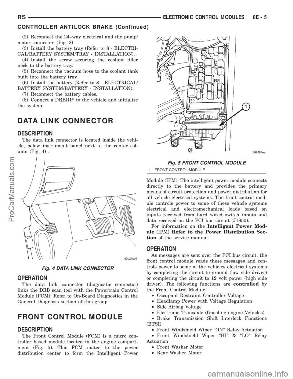
The data link connector is located inside the vehi-
cle, below instrument panel next to the center col-
umn (Fig. 4) .
OPERATION
The data link connector (diagnostic connector)
links the DRB scan tool with the Powertrain Control
Module (PCM). Refer to On-Board Diagnostics in the
General Diagnosis section of this group.
FRONT CONTROL MODULE
DESCRIPTION
The Front Control Module (FCM) is a micro con-
troller based module located in the engine compart-
ment (Fig. 5). This FCM mates to the power
distribution center to form the Intelligent PowerModule (IPM). The intelligent power module connects
directly to the battery and provides the primary
means of circuit protection and power distribution for
all vehicle electrical systems. The front control mod-
ule controls power to some of these vehicle systems
electrical and electromechanical loads based on
inputs received from hard wired switch inputs and
data received on the PCI bus circuit (J1850).
For information on theIntelligent Power Mod-
ule(IPM)Refer to the Power Distribution Sec-
tionof the service manual.
OPERATION
As messages are sent over the PCI bus circuit, the
front control module reads these messages and con-
trols power to some of the vehicles electrical systems
by completing the circuit to ground (low side driver)
or completing the circuit to 12 volt power (high side
driver). The following functions arecontrolledby
the Front Control Module:
²Occupant Restraint Controller Voltage
²Headlamp Power with Voltage Regulation
²Side Airbag Voltage
²Electronic Transaxle (Gasoline engine Vehicles)
²Brake Transmission Shift Interlock Functions
(BTSI)
²Front Windshield Wiper ªONº Relay Actuation
²Front Windshield Wiper ªHIº & ªLOº Relay
Actuation
²Front Washer Motor
²Rear Washer Motor
Fig. 4 DATA LINK CONNECTOR
Fig. 5 FRONT CONTROL MODULE
1 - FRONT CONTROL MODULE
RSELECTRONIC CONTROL MODULES8E-5
CONTROLLER ANTILOCK BRAKE (Continued)
ProCarManuals.com