Page 2313 of 2321

OPERATION
The engines use Exhaust Gas Recirculation (EGR)
systems. The EGR system reduces oxides of nitrogen
(NOx) in engine exhaust and helps prevent detona-
tion (engine knock). Under normal operating condi-tions, engine cylinder temperature can reach more
than 3000ÉF. Formation of NOx increases proportion-
ally with combustion temperature. To reduce the
emission of these oxides, the cylinder temperature
must be lowered. The system allows a predetermined
amount of hot exhaust gas to recirculate and dilute
the incoming air/fuel mixture. The diluted air/fuel
mixture reduces peak flame temperature during com-
bustion.
REMOVAL
(1) Remove engine cover (Refer to 9 - ENGINE -
REMOVAL).
(2) Remove front wiper unit (Refer to 8 - ELEC-
TRICAL/WIPERS/WASHERS/WIPER MODULE -
REMOVAL).
(3) Disconnect EGR valve vacuum line.
(4) Remove EGR cooler to EGR valve retaining
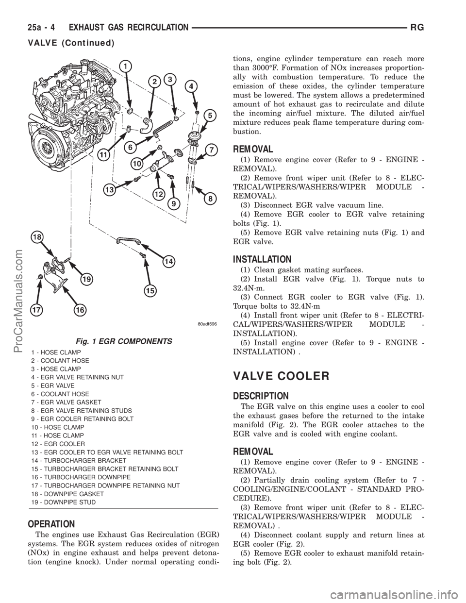
bolts (Fig. 1).
(5) Remove EGR valve retaining nuts (Fig. 1) and
EGR valve.
INSTALLATION
(1) Clean gasket mating surfaces.
(2) Install EGR valve (Fig. 1). Torque nuts to
32.4N´m.
(3) Connect EGR cooler to EGR valve (Fig. 1).
Torque bolts to 32.4N´m
(4) Install front wiper unit (Refer to 8 - ELECTRI-
CAL/WIPERS/WASHERS/WIPER MODULE -
INSTALLATION).
(5) Install engine cover (Refer to 9 - ENGINE -
INSTALLATION) .
VALVE COOLER
DESCRIPTION
The EGR valve on this engine uses a cooler to cool
the exhaust gases before the returned to the intake
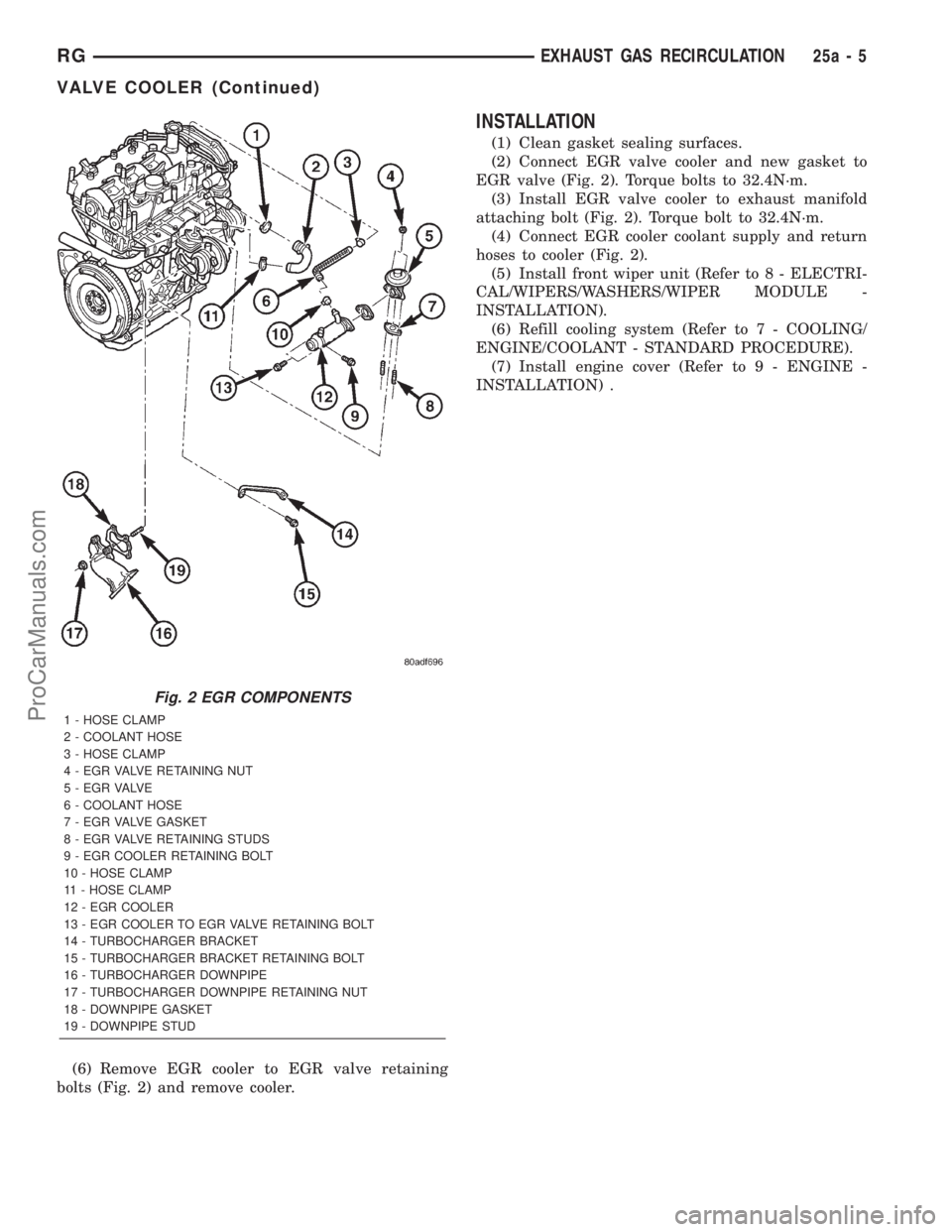
manifold (Fig. 2). The EGR cooler attaches to the
EGR valve and is cooled with engine coolant.
REMOVAL
(1) Remove engine cover (Refer to 9 - ENGINE -
REMOVAL).
(2) Partially drain cooling system (Refer to 7 -
COOLING/ENGINE/COOLANT - STANDARD PRO-
CEDURE).
(3) Remove front wiper unit (Refer to 8 - ELEC-
TRICAL/WIPERS/WASHERS/WIPER MODULE -
REMOVAL) .
(4) Disconnect coolant supply and return lines at
EGR cooler (Fig. 2).
(5) Remove EGR cooler to exhaust manifold retain-
ing bolt (Fig. 2).
Fig. 1 EGR COMPONENTS
1 - HOSE CLAMP
2 - COOLANT HOSE
3 - HOSE CLAMP
4 - EGR VALVE RETAINING NUT
5 - E G R VA LV E
6 - COOLANT HOSE
7 - EGR VALVE GASKET
8 - EGR VALVE RETAINING STUDS
9 - EGR COOLER RETAINING BOLT
10 - HOSE CLAMP
11 - HOSE CLAMP
12 - EGR COOLER
13 - EGR COOLER TO EGR VALVE RETAINING BOLT
14 - TURBOCHARGER BRACKET
15 - TURBOCHARGER BRACKET RETAINING BOLT
16 - TURBOCHARGER DOWNPIPE
17 - TURBOCHARGER DOWNPIPE RETAINING NUT
18 - DOWNPIPE GASKET
19 - DOWNPIPE STUD
25a - 4 EXHAUST GAS RECIRCULATIONRG
VALVE (Continued)
ProCarManuals.com
Page 2314 of 2321

(6) Remove EGR cooler to EGR valve retaining
bolts (Fig. 2) and remove cooler.
INSTALLATION
(1) Clean gasket sealing surfaces.
(2) Connect EGR valve cooler and new gasket to
EGR valve (Fig. 2). Torque bolts to 32.4N´m.
(3) Install EGR valve cooler to exhaust manifold
attaching bolt (Fig. 2). Torque bolt to 32.4N´m.
(4) Connect EGR cooler coolant supply and return
hoses to cooler (Fig. 2).
(5) Install front wiper unit (Refer to 8 - ELECTRI-
CAL/WIPERS/WASHERS/WIPER MODULE -
INSTALLATION).
(6) Refill cooling system (Refer to 7 - COOLING/
ENGINE/COOLANT - STANDARD PROCEDURE).
(7) Install engine cover (Refer to 9 - ENGINE -
INSTALLATION) .
Fig. 2 EGR COMPONENTS
1 - HOSE CLAMP
2 - COOLANT HOSE
3 - HOSE CLAMP
4 - EGR VALVE RETAINING NUT
5 - E G R VA LV E
6 - COOLANT HOSE
7 - EGR VALVE GASKET
8 - EGR VALVE RETAINING STUDS
9 - EGR COOLER RETAINING BOLT
10 - HOSE CLAMP
11 - HOSE CLAMP
12 - EGR COOLER
13 - EGR COOLER TO EGR VALVE RETAINING BOLT
14 - TURBOCHARGER BRACKET
15 - TURBOCHARGER BRACKET RETAINING BOLT
16 - TURBOCHARGER DOWNPIPE
17 - TURBOCHARGER DOWNPIPE RETAINING NUT
18 - DOWNPIPE GASKET
19 - DOWNPIPE STUD
RGEXHAUST GAS RECIRCULATION25a-5
VALVE COOLER (Continued)
ProCarManuals.com
Page 2316 of 2321

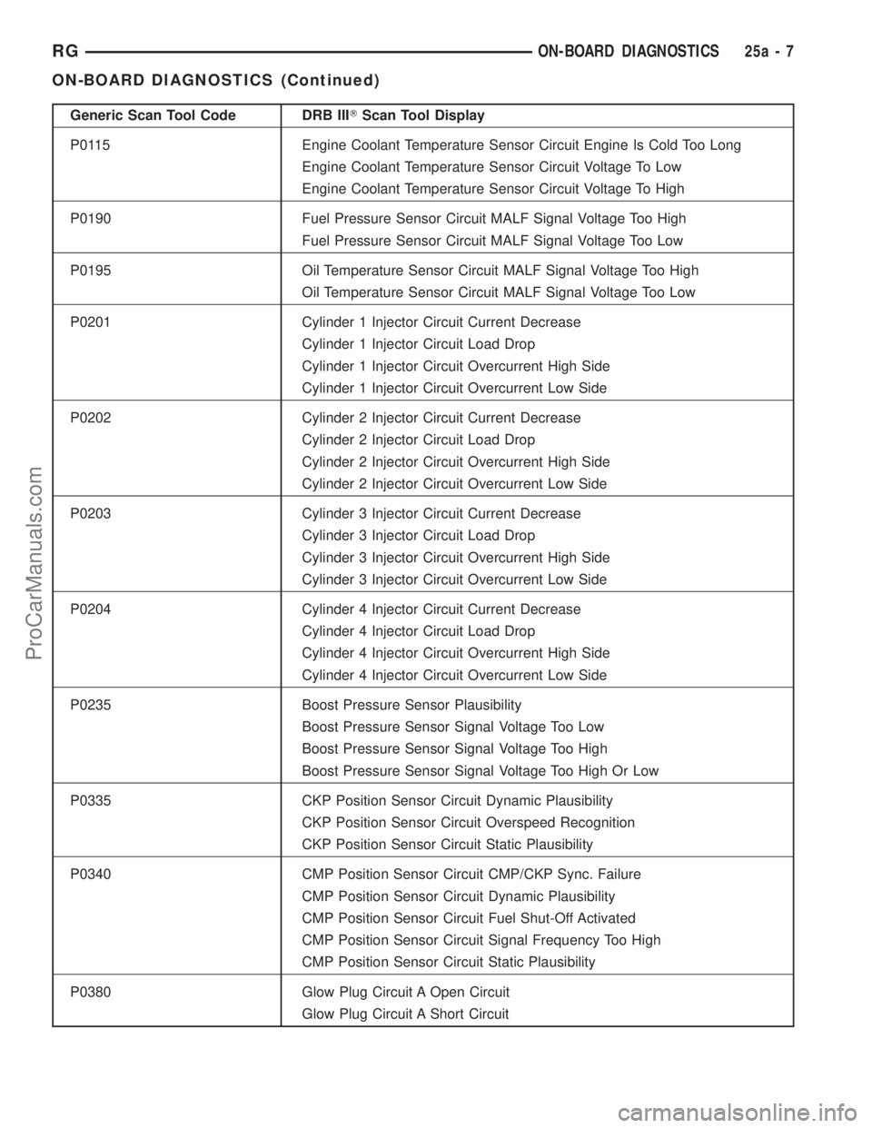
Generic Scan Tool Code DRB IIITScan Tool Display
P0115 Engine Coolant Temperature Sensor Circuit Engine Is Cold Too Long
Engine Coolant Temperature Sensor Circuit Voltage To Low
Engine Coolant Temperature Sensor Circuit Voltage To High
P0190 Fuel Pressure Sensor Circuit MALF Signal Voltage Too High
Fuel Pressure Sensor Circuit MALF Signal Voltage Too Low
P0195 Oil Temperature Sensor Circuit MALF Signal Voltage Too High
Oil Temperature Sensor Circuit MALF Signal Voltage Too Low
P0201 Cylinder 1 Injector Circuit Current Decrease
Cylinder 1 Injector Circuit Load Drop
Cylinder 1 Injector Circuit Overcurrent High Side
Cylinder 1 Injector Circuit Overcurrent Low Side
P0202 Cylinder 2 Injector Circuit Current Decrease
Cylinder 2 Injector Circuit Load Drop
Cylinder 2 Injector Circuit Overcurrent High Side
Cylinder 2 Injector Circuit Overcurrent Low Side
P0203 Cylinder 3 Injector Circuit Current Decrease
Cylinder 3 Injector Circuit Load Drop
Cylinder 3 Injector Circuit Overcurrent High Side
Cylinder 3 Injector Circuit Overcurrent Low Side
P0204 Cylinder 4 Injector Circuit Current Decrease
Cylinder 4 Injector Circuit Load Drop
Cylinder 4 Injector Circuit Overcurrent High Side
Cylinder 4 Injector Circuit Overcurrent Low Side
P0235 Boost Pressure Sensor Plausibility
Boost Pressure Sensor Signal Voltage Too Low
Boost Pressure Sensor Signal Voltage Too High
Boost Pressure Sensor Signal Voltage Too High Or Low
P0335 CKP Position Sensor Circuit Dynamic Plausibility
CKP Position Sensor Circuit Overspeed Recognition
CKP Position Sensor Circuit Static Plausibility
P0340 CMP Position Sensor Circuit CMP/CKP Sync. Failure
CMP Position Sensor Circuit Dynamic Plausibility
CMP Position Sensor Circuit Fuel Shut-Off Activated
CMP Position Sensor Circuit Signal Frequency Too High
CMP Position Sensor Circuit Static Plausibility
P0380 Glow Plug Circuit A Open Circuit
Glow Plug Circuit A Short Circuit
RGON-BOARD DIAGNOSTICS25a-7
ON-BOARD DIAGNOSTICS (Continued)
ProCarManuals.com