2001 DODGE TOWN AND COUNTRY clock
[x] Cancel search: clockPage 1666 of 2321
DISASSEMBLY
CAUTION: If transaxle failure has occurred, it is
necessary to flush the transaxle oil cooler and lines
to remove debris and particles that could contami-
nate and/or fail a new or rebuilt unit. (Refer to 7 -
COOLING/TRANSMISSION - STANDARD PROCE-
DURE)
NOTE: If transaxle is being overhauled (clutch
and/or seal replacement) or replaced, it is neces-
sary to perform the TCM Quick Learn Procedure.
(Refer to 8 - ELECTRICAL/ELECTRONIC CONTROL
MODULES/TRANSMISSION CONTROL MODULE -
STANDARD PROCEDURE)
NOTE: This procedure does not include final drive
(differential) disassembly.
(1) Remove input and output speed sensors.
(2) Remove three (3) solenoid/pressure switch
assembly-to-case bolts.
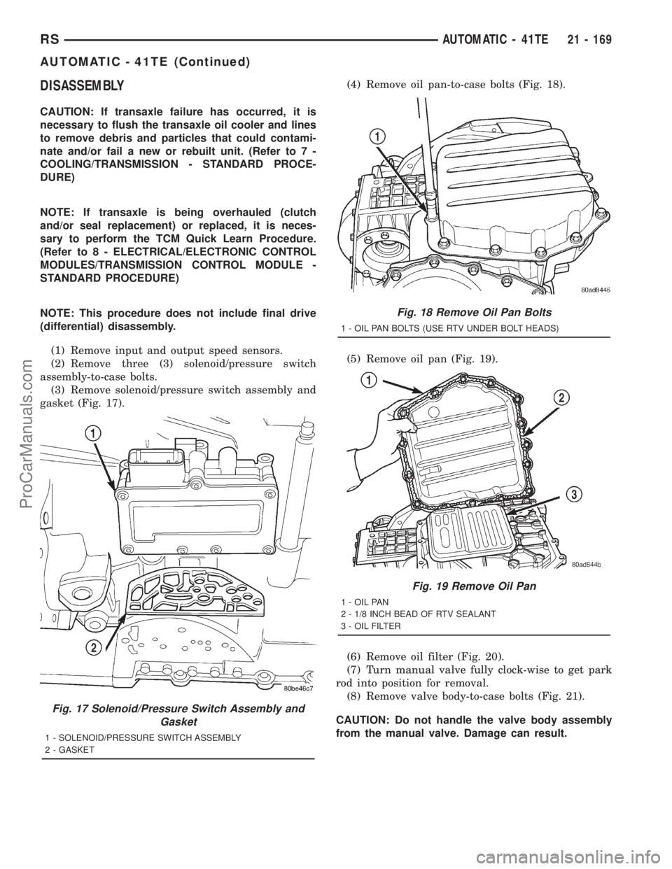
(3) Remove solenoid/pressure switch assembly and
gasket (Fig. 17).(4) Remove oil pan-to-case bolts (Fig. 18).
(5) Remove oil pan (Fig. 19).
(6) Remove oil filter (Fig. 20).
(7) Turn manual valve fully clock-wise to get park
rod into position for removal.
(8) Remove valve body-to-case bolts (Fig. 21).
CAUTION: Do not handle the valve body assembly
from the manual valve. Damage can result.
Fig. 17 Solenoid/Pressure Switch Assembly and
Gasket
1 - SOLENOID/PRESSURE SWITCH ASSEMBLY
2 - GASKET
Fig. 18 Remove Oil Pan Bolts
1 - OIL PAN BOLTS (USE RTV UNDER BOLT HEADS)
Fig. 19 Remove Oil Pan
1 - OIL PAN
2 - 1/8 INCH BEAD OF RTV SEALANT
3 - OIL FILTER
RSAUTOMATIC - 41TE21 - 169
AUTOMATIC - 41TE (Continued)
ProCarManuals.com
Page 1690 of 2321
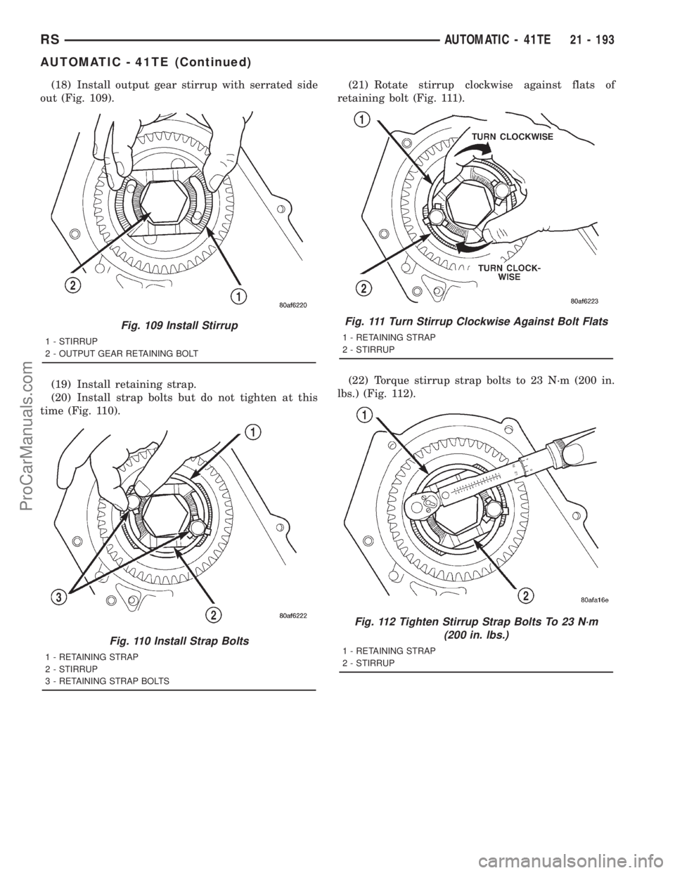
(18) Install output gear stirrup with serrated side
out (Fig. 109).
(19) Install retaining strap.
(20) Install strap bolts but do not tighten at this
time (Fig. 110).(21) Rotate stirrup clockwise against flats of
retaining bolt (Fig. 111).
(22) Torque stirrup strap bolts to 23 N´m (200 in.
lbs.) (Fig. 112).
Fig. 109 Install Stirrup
1 - STIRRUP
2 - OUTPUT GEAR RETAINING BOLT
Fig. 110 Install Strap Bolts
1 - RETAINING STRAP
2 - STIRRUP
3 - RETAINING STRAP BOLTS
Fig. 111 Turn Stirrup Clockwise Against Bolt Flats
1 - RETAINING STRAP
2 - STIRRUP
Fig. 112 Tighten Stirrup Strap Bolts To 23 N´m
(200 in. lbs.)
1 - RETAINING STRAP
2 - STIRRUP
RSAUTOMATIC - 41TE21 - 193
AUTOMATIC - 41TE (Continued)
ProCarManuals.com
Page 1704 of 2321
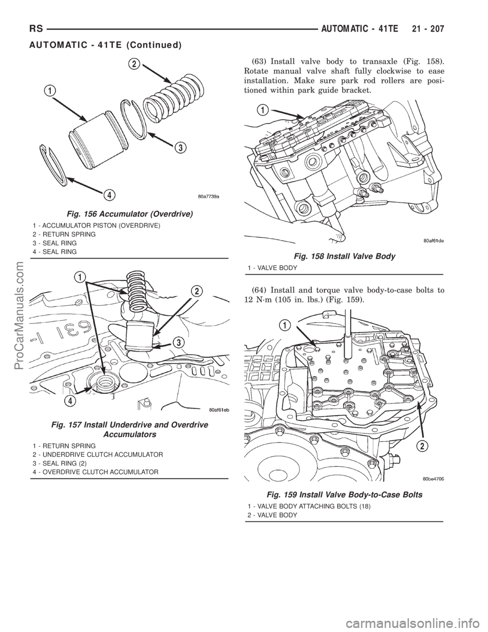
(63) Install valve body to transaxle (Fig. 158).
Rotate manual valve shaft fully clockwise to ease
installation. Make sure park rod rollers are posi-
tioned within park guide bracket.
(64) Install and torque valve body-to-case bolts to
12 N´m (105 in. lbs.) (Fig. 159).
Fig. 156 Accumulator (Overdrive)
1 - ACCUMULATOR PISTON (OVERDRIVE)
2 - RETURN SPRING
3 - SEAL RING
4 - SEAL RING
Fig. 157 Install Underdrive and Overdrive
Accumulators
1 - RETURN SPRING
2 - UNDERDRIVE CLUTCH ACCUMULATOR
3 - SEAL RING (2)
4 - OVERDRIVE CLUTCH ACCUMULATOR
Fig. 158 Install Valve Body
1 - VALVE BODY
Fig. 159 Install Valve Body-to-Case Bolts
1 - VALVE BODY ATTACHING BOLTS (18)
2 - VALVE BODY
RSAUTOMATIC - 41TE21 - 207
AUTOMATIC - 41TE (Continued)
ProCarManuals.com
Page 1780 of 2321
STATOR
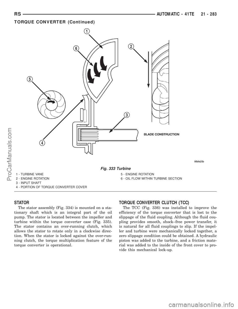
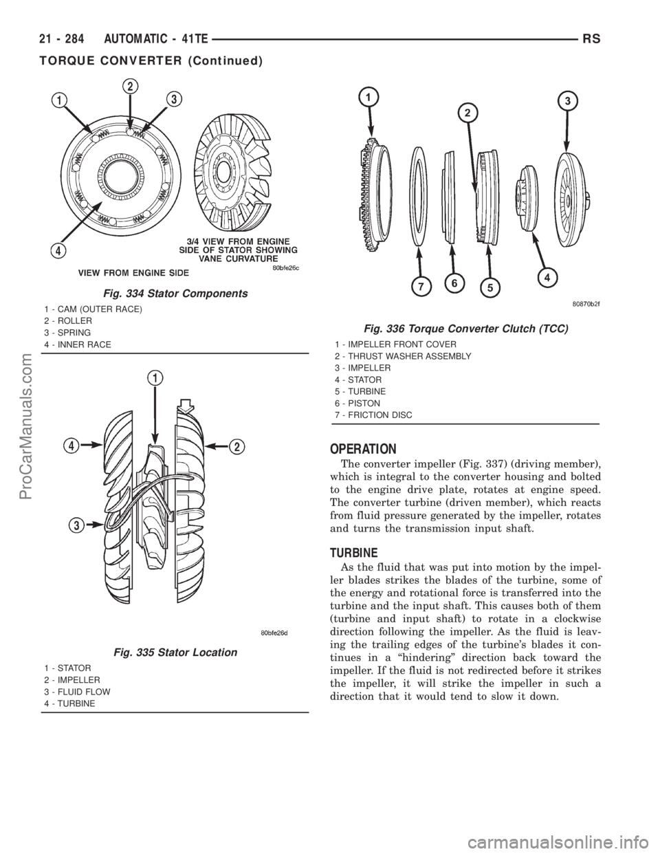
The stator assembly (Fig. 334) is mounted on a sta-
tionary shaft which is an integral part of the oil
pump. The stator is located between the impeller and
turbine within the torque converter case (Fig. 335).
The stator contains an over-running clutch, which
allows the stator to rotate only in a clockwise direc-
tion. When the stator is locked against the over-run-
ning clutch, the torque multiplication feature of the
torque converter is operational.
TORQUE CONVERTER CLUTCH (TCC)
The TCC (Fig. 336) was installed to improve the
efficiency of the torque converter that is lost to the
slippage of the fluid coupling. Although the fluid cou-
pling provides smooth, shock±free power transfer, it
is natural for all fluid couplings to slip. If the impel-
ler and turbine were mechanically locked together, a
zero slippage condition could be obtained. A hydraulic
piston was added to the turbine, and a friction mate-
rial was added to the inside of the front cover to pro-
vide this mechanical lock-up.
Fig. 333 Turbine
1 - TURBINE VANE
2 - ENGINE ROTATION
3 - INPUT SHAFT
4 - PORTION OF TORQUE CONVERTER COVER5 - ENGINE ROTATION
6 - OIL FLOW WITHIN TURBINE SECTION
RSAUTOMATIC - 41TE21 - 283
TORQUE CONVERTER (Continued)
ProCarManuals.com
Page 1781 of 2321
OPERATION
The converter impeller (Fig. 337) (driving member),
which is integral to the converter housing and bolted
to the engine drive plate, rotates at engine speed.
The converter turbine (driven member), which reacts
from fluid pressure generated by the impeller, rotates
and turns the transmission input shaft.
TURBINE
As the fluid that was put into motion by the impel-
ler blades strikes the blades of the turbine, some of
the energy and rotational force is transferred into the
turbine and the input shaft. This causes both of them
(turbine and input shaft) to rotate in a clockwise
direction following the impeller. As the fluid is leav-
ing the trailing edges of the turbine's blades it con-
tinues in a ªhinderingº direction back toward the
impeller. If the fluid is not redirected before it strikes
the impeller, it will strike the impeller in such a
direction that it would tend to slow it down.
Fig. 334 Stator Components
1 - CAM (OUTER RACE)
2 - ROLLER
3 - SPRING
4 - INNER RACE
Fig. 335 Stator Location
1-STATOR
2 - IMPELLER
3 - FLUID FLOW
4 - TURBINE
Fig. 336 Torque Converter Clutch (TCC)
1 - IMPELLER FRONT COVER
2 - THRUST WASHER ASSEMBLY
3 - IMPELLER
4-STATOR
5 - TURBINE
6 - PISTON
7 - FRICTION DISC
21 - 284 AUTOMATIC - 41TERS
TORQUE CONVERTER (Continued)
ProCarManuals.com
Page 1782 of 2321
STATOR
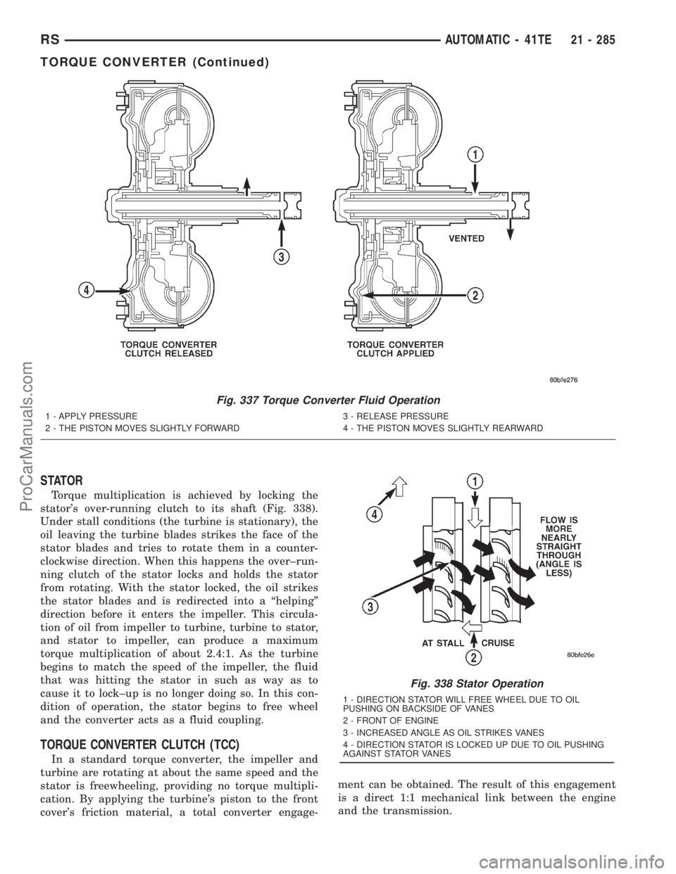
Torque multiplication is achieved by locking the
stator's over-running clutch to its shaft (Fig. 338).
Under stall conditions (the turbine is stationary), the
oil leaving the turbine blades strikes the face of the
stator blades and tries to rotate them in a counter-
clockwise direction. When this happens the over±run-
ning clutch of the stator locks and holds the stator
from rotating. With the stator locked, the oil strikes
the stator blades and is redirected into a ªhelpingº
direction before it enters the impeller. This circula-
tion of oil from impeller to turbine, turbine to stator,
and stator to impeller, can produce a maximum
torque multiplication of about 2.4:1. As the turbine
begins to match the speed of the impeller, the fluid
that was hitting the stator in such as way as to
cause it to lock±up is no longer doing so. In this con-
dition of operation, the stator begins to free wheel
and the converter acts as a fluid coupling.
TORQUE CONVERTER CLUTCH (TCC)
In a standard torque converter, the impeller and
turbine are rotating at about the same speed and the
stator is freewheeling, providing no torque multipli-
cation. By applying the turbine's piston to the front
cover's friction material, a total converter engage-ment can be obtained. The result of this engagement
is a direct 1:1 mechanical link between the engine
and the transmission.
Fig. 337 Torque Converter Fluid Operation
1 - APPLY PRESSURE
2 - THE PISTON MOVES SLIGHTLY FORWARD3 - RELEASE PRESSURE
4 - THE PISTON MOVES SLIGHTLY REARWARD
Fig. 338 Stator Operation
1 - DIRECTION STATOR WILL FREE WHEEL DUE TO OIL
PUSHING ON BACKSIDE OF VANES
2 - FRONT OF ENGINE
3 - INCREASED ANGLE AS OIL STRIKES VANES
4 - DIRECTION STATOR IS LOCKED UP DUE TO OIL PUSHING
AGAINST STATOR VANES
RSAUTOMATIC - 41TE21 - 285
TORQUE CONVERTER (Continued)
ProCarManuals.com
Page 1788 of 2321
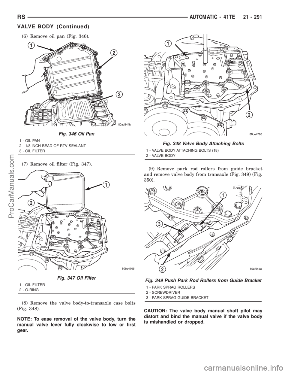
(6) Remove oil pan (Fig. 346).
(7) Remove oil filter (Fig. 347).
(8) Remove the valve body-to-transaxle case bolts
(Fig. 348).
NOTE: To ease removal of the valve body, turn the
manual valve lever fully clockwise to low or first
gear.(9) Remove park rod rollers from guide bracket
and remove valve body from transaxle (Fig. 349) (Fig.
350).
CAUTION: The valve body manual shaft pilot may
distort and bind the manual valve if the valve body
is mishandled or dropped.
Fig. 346 Oil Pan
1 - OIL PAN
2 - 1/8 INCH BEAD OF RTV SEALANT
3 - OIL FILTER
Fig. 347 Oil Filter
1 - OIL FILTER
2 - O-RING
Fig. 348 Valve Body Attaching Bolts
1 - VALVE BODY ATTACHING BOLTS (18)
2 - VALVE BODY
Fig. 349 Push Park Rod Rollers from Guide Bracket
1 - PARK SPRAG ROLLERS
2 - SCREWDRIVER
3 - PARK SPRAG GUIDE BRACKET
RSAUTOMATIC - 41TE21 - 291
VALVE BODY (Continued)
ProCarManuals.com
Page 1810 of 2321
DIAGNOSIS AND TESTING - COMMON
PROBLEM CAUSES
The majority of transaxle malfunctions are a result
of:
²Insufficient lubrication
²Incorrect lubricant
²Misassembled or damaged internal components
²Improper operation
HARD SHIFTING
Hard shifting may be caused by a misadjusted
crossover cable. If hard shifting is accompanied by
gear clash, synchronizer clutch and stop rings or gear
teeth may be worn or damaged.
Hard shifting may also be caused by a binding or
broken shift cover mechanism. Remove shift cover
and verify smooth operation. Replace as necessary.
Misassembled synchronizer components also cause
shifting problems. Incorrectly installed synchronizer
sleeves, keys, balls, or springs can cause shift prob-
lems.
NOISY OPERATION
Transaxle noise is most often a result of worn or
damaged components. Chipped, broken gear or syn-
chronizer teeth, and brinnelled, spalled bearings all
cause noise.
Abnormal wear and damage to the internal compo-
nents is frequently the end result of insufficient
lubricant.
SLIPS OUT OF GEAR
Transaxle disengagement may be caused by mis-
aligned or damaged shift components, or worn teeth
on the drive gears or synchronizer components. Incor-
rect assembly also causes gear disengagement. Check
for missing snap rings.
LOW LUBRICANT LEVEL
Insufficient transaxle lubricant is usually the
result of leaks, or inaccurate fluid level check or refill
method. Leakage is evident by the presence of oil
around the leak point. If leakage is not evident, the
condition is probably the result of an underfill.
If air±powered lubrication equipment is used to fill
a transaxle, be sure the equipment is properly cali-
brated. Equipment out of calibration can lead to an
underfill condition.
CLUTCH PROBLEMS
Worn, damaged, or misaligned clutch components
can cause difficult shifting, gear clash, and noise.
A worn or damaged clutch disc, pressure plate, or
release bearing can cause hard shifting and gear
clash.
REMOVAL
REMOVAL - 2.4L GAS
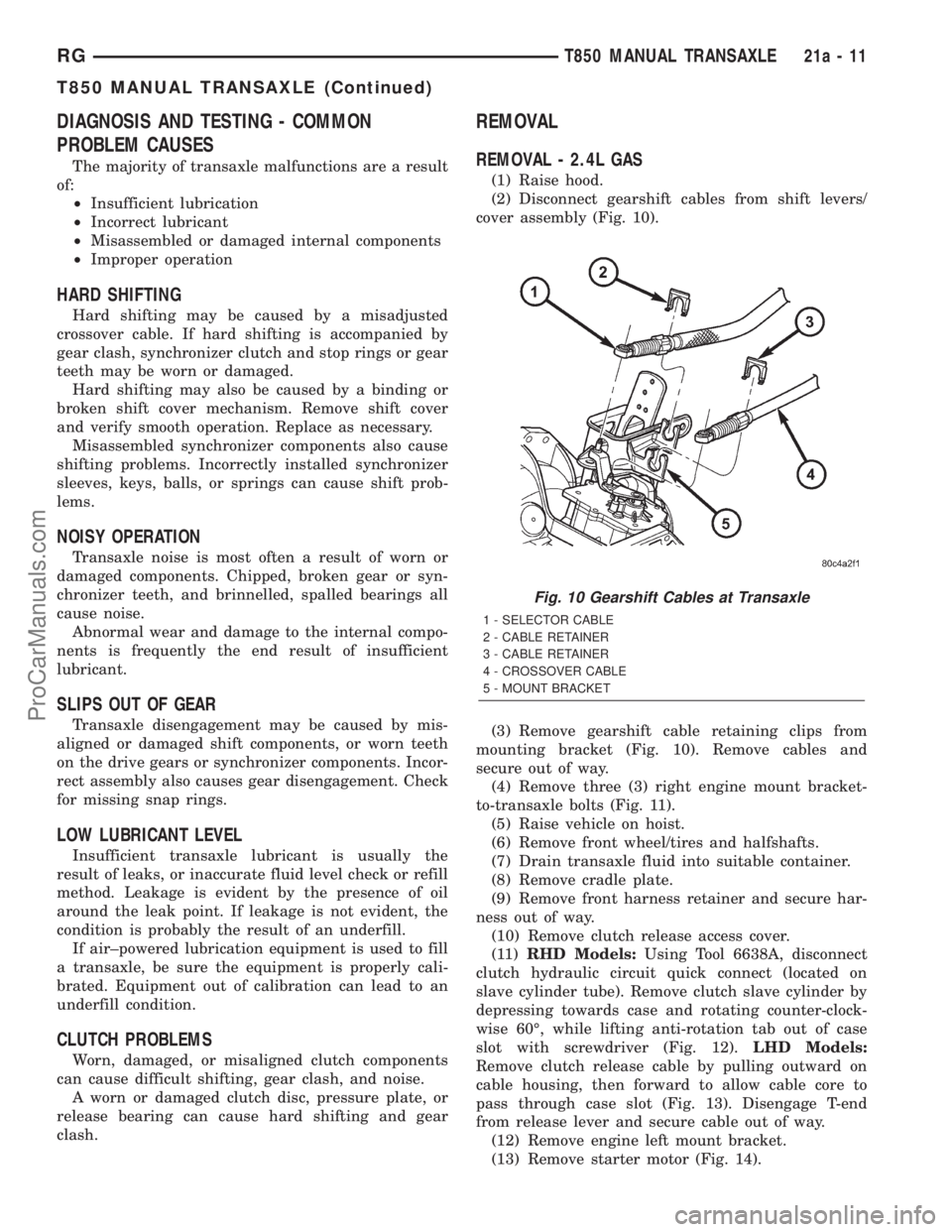
(1) Raise hood.
(2) Disconnect gearshift cables from shift levers/
cover assembly (Fig. 10).
(3) Remove gearshift cable retaining clips from
mounting bracket (Fig. 10). Remove cables and
secure out of way.
(4) Remove three (3) right engine mount bracket-
to-transaxle bolts (Fig. 11).
(5) Raise vehicle on hoist.
(6) Remove front wheel/tires and halfshafts.
(7) Drain transaxle fluid into suitable container.
(8) Remove cradle plate.
(9) Remove front harness retainer and secure har-
ness out of way.
(10) Remove clutch release access cover.
(11)RHD Models:Using Tool 6638A, disconnect
clutch hydraulic circuit quick connect (located on
slave cylinder tube). Remove clutch slave cylinder by
depressing towards case and rotating counter-clock-
wise 60É, while lifting anti-rotation tab out of case
slot with screwdriver (Fig. 12).LHD Models:
Remove clutch release cable by pulling outward on
cable housing, then forward to allow cable core to
pass through case slot (Fig. 13). Disengage T-end
from release lever and secure cable out of way.
(12) Remove engine left mount bracket.
(13) Remove starter motor (Fig. 14).
Fig. 10 Gearshift Cables at Transaxle
1 - SELECTOR CABLE
2 - CABLE RETAINER
3 - CABLE RETAINER
4 - CROSSOVER CABLE
5 - MOUNT BRACKET
RGT850 MANUAL TRANSAXLE21a-11
T850 MANUAL TRANSAXLE (Continued)
ProCarManuals.com