2001 DODGE TOWN AND COUNTRY clock
[x] Cancel search: clockPage 1866 of 2321
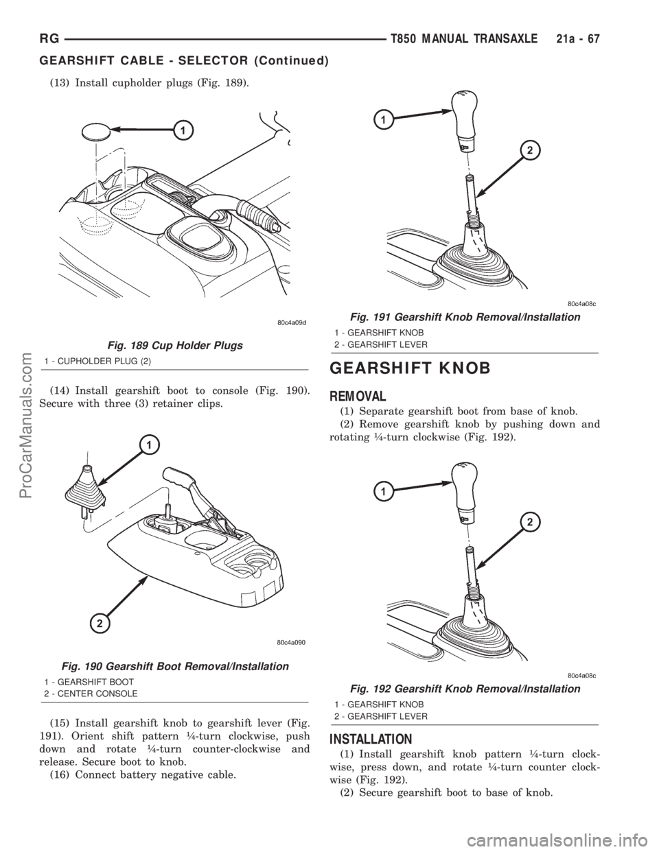
(13) Install cupholder plugs (Fig. 189).
(14) Install gearshift boot to console (Fig. 190).
Secure with three (3) retainer clips.
(15) Install gearshift knob to gearshift lever (Fig.
191). Orient shift pattern ò-turn clockwise, push
down and rotate ò-turn counter-clockwise and
release. Secure boot to knob.
(16) Connect battery negative cable.
GEARSHIFT KNOB
REMOVAL
(1) Separate gearshift boot from base of knob.
(2) Remove gearshift knob by pushing down and
rotating ò-turn clockwise (Fig. 192).
INSTALLATION
(1) Install gearshift knob pattern ò-turn clock-
wise, press down, and rotate ò-turn counter clock-
wise (Fig. 192).
(2) Secure gearshift boot to base of knob.
Fig. 189 Cup Holder Plugs
1 - CUPHOLDER PLUG (2)
Fig. 190 Gearshift Boot Removal/Installation
1 - GEARSHIFT BOOT
2 - CENTER CONSOLE
Fig. 191 Gearshift Knob Removal/Installation
1 - GEARSHIFT KNOB
2 - GEARSHIFT LEVER
Fig. 192 Gearshift Knob Removal/Installation
1 - GEARSHIFT KNOB
2 - GEARSHIFT LEVER
RGT850 MANUAL TRANSAXLE21a-67
GEARSHIFT CABLE - SELECTOR (Continued)
ProCarManuals.com
Page 1867 of 2321
GEARSHIFT MECHANISM
REMOVAL
(1) Disconnect battery negative cable.
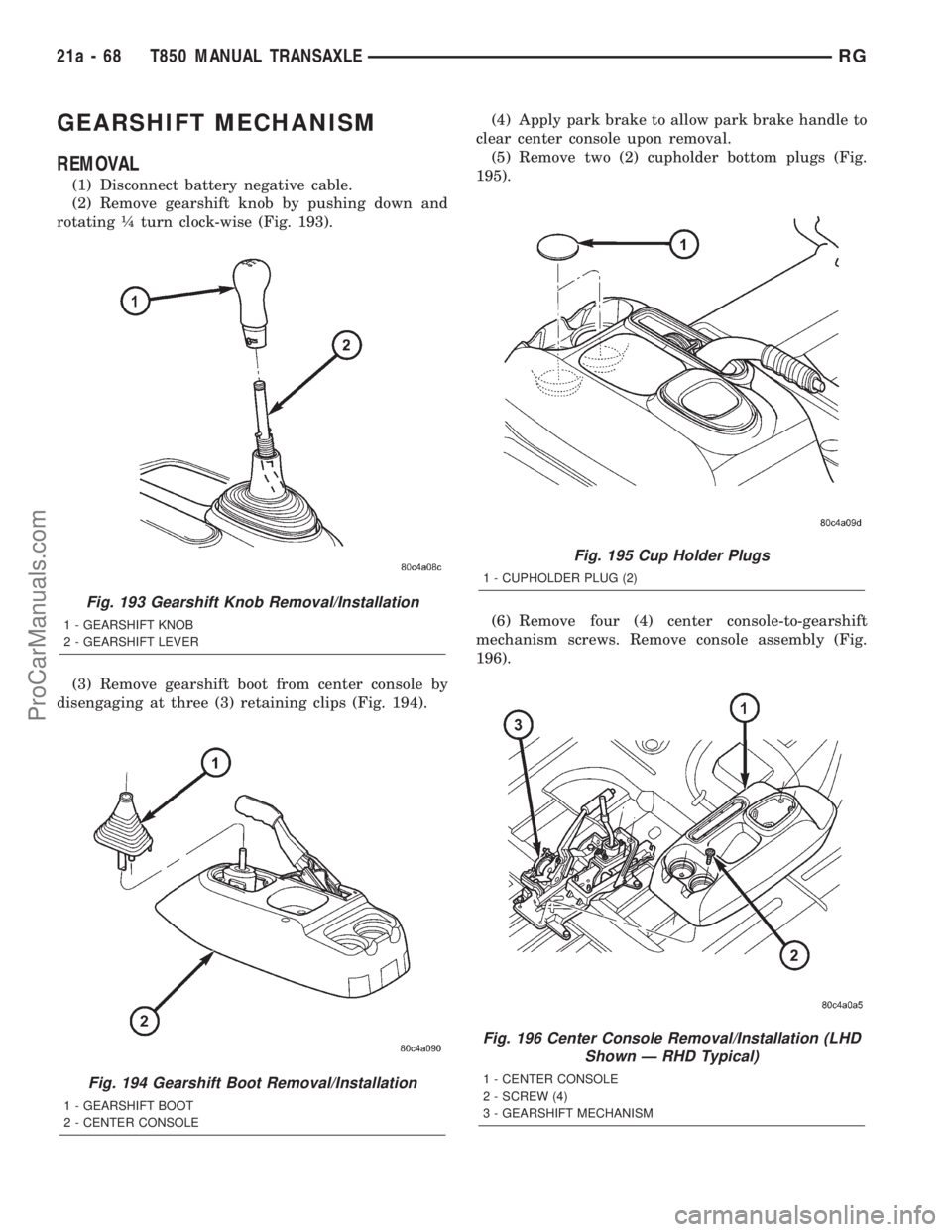
(2) Remove gearshift knob by pushing down and
rotating ò turn clock-wise (Fig. 193).
(3) Remove gearshift boot from center console by
disengaging at three (3) retaining clips (Fig. 194).(4) Apply park brake to allow park brake handle to
clear center console upon removal.
(5) Remove two (2) cupholder bottom plugs (Fig.
195).
(6) Remove four (4) center console-to-gearshift
mechanism screws. Remove console assembly (Fig.
196).
Fig. 193 Gearshift Knob Removal/Installation
1 - GEARSHIFT KNOB
2 - GEARSHIFT LEVER
Fig. 194 Gearshift Boot Removal/Installation
1 - GEARSHIFT BOOT
2 - CENTER CONSOLE
Fig. 195 Cup Holder Plugs
1 - CUPHOLDER PLUG (2)
Fig. 196 Center Console Removal/Installation (LHD
Shown Ð RHD Typical)
1 - CENTER CONSOLE
2 - SCREW (4)
3 - GEARSHIFT MECHANISM
21a - 68 T850 MANUAL TRANSAXLERG
ProCarManuals.com
Page 1871 of 2321
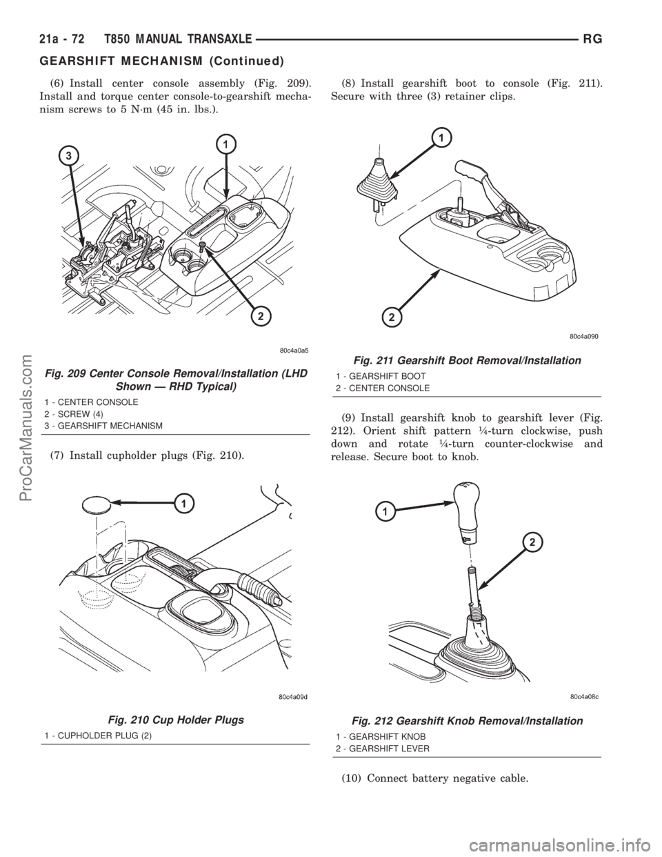
(6) Install center console assembly (Fig. 209).
Install and torque center console-to-gearshift mecha-
nism screws to 5 N´m (45 in. lbs.).
(7) Install cupholder plugs (Fig. 210).(8) Install gearshift boot to console (Fig. 211).
Secure with three (3) retainer clips.
(9) Install gearshift knob to gearshift lever (Fig.
212). Orient shift pattern ò-turn clockwise, push
down and rotate ò-turn counter-clockwise and
release. Secure boot to knob.
(10) Connect battery negative cable.
Fig. 209 Center Console Removal/Installation (LHD
Shown Ð RHD Typical)
1 - CENTER CONSOLE
2 - SCREW (4)
3 - GEARSHIFT MECHANISM
Fig. 210 Cup Holder Plugs
1 - CUPHOLDER PLUG (2)
Fig. 211 Gearshift Boot Removal/Installation
1 - GEARSHIFT BOOT
2 - CENTER CONSOLE
Fig. 212 Gearshift Knob Removal/Installation
1 - GEARSHIFT KNOB
2 - GEARSHIFT LEVER
21a - 72 T850 MANUAL TRANSAXLERG
GEARSHIFT MECHANISM (Continued)
ProCarManuals.com
Page 1896 of 2321
TIRES/WHEELS
TABLE OF CONTENTS
page page
TIRES/WHEELS
DIAGNOSIS AND TESTING..................1
TIRE AND WHEEL VIBRATION..............1
STANDARD PROCEDURE...................4
TIRE AND WHEEL BALANCE...............4
TIRE AND WHEEL MATCH MOUNTING.......6
TIRE AND WHEEL ROTATION..............6
REMOVAL...............................7
INSTALLATION............................7
TIRES
DESCRIPTION............................8
DIAGNOSIS AND TESTING..................9
TIRE NOISE............................9
TIRE/VEHICLE LEAD.....................9
TIRE WEAR PATTERNS..................11
TREAD WEAR INDICATORS...............11
STANDARD PROCEDURE..................11
TIRE INFLATION PRESSURES.............11
TIRE PRESSURE FOR HIGH SPEED
OPERATION...........................12TIRE LEAK REPAIRING..................12
CLEANING..............................13
WHEELS
DESCRIPTION...........................13
DIAGNOSIS AND TESTING.................13
WHEEL INSPECTION....................13
CLEANING..............................14
SPECIFICATIONS........................14
WHEEL COVER
DESCRIPTION...........................14
REMOVAL..............................14
INSTALLATION...........................14
WHEEL MOUNTING STUDS - FRONT
REMOVAL..............................15
INSTALLATION...........................16
WHEEL MOUNTING STUDS - REAR
REMOVAL..............................16
INSTALLATION...........................17
TIRES/WHEELS
DIAGNOSIS AND TESTING - TIRE AND WHEEL
VIBRATION
Tire and wheel imbalance, runout and force varia-
tion can cause vehicles to exhibit steering wheel
vibration.
VISUAL INSPECTION
Visual inspection of the vehicle is recommended
prior to road testing or performing any other proce-
dure. Raise vehicle on a suitable hoist. Refer to
Hoisting in Lubrication and Maintenance.
Inspect for the following:
²Verify correct (OEM) wheel and tire, as well as
correct wheel weights. Aluminum wheels require
unique wheel weights. They are designed to fit the
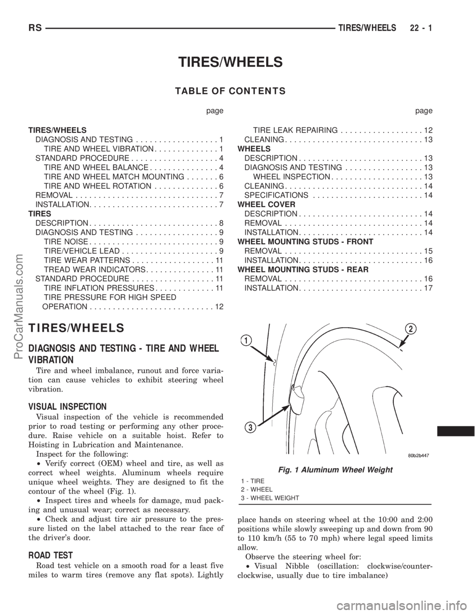
contour of the wheel (Fig. 1).
²Inspect tires and wheels for damage, mud pack-
ing and unusual wear; correct as necessary.
²Check and adjust tire air pressure to the pres-
sure listed on the label attached to the rear face of
the driver's door.
ROAD TEST
Road test vehicle on a smooth road for a least five
miles to warm tires (remove any flat spots). Lightlyplace hands on steering wheel at the 10:00 and 2:00
positions while slowly sweeping up and down from 90
to 110 km/h (55 to 70 mph) where legal speed limits
allow.
Observe the steering wheel for:
²Visual Nibble (oscillation: clockwise/counter-
clockwise, usually due to tire imbalance)
Fig. 1 Aluminum Wheel Weight
1 - TIRE
2 - WHEEL
3 - WHEEL WEIGHT
RSTIRES/WHEELS22-1
ProCarManuals.com
Page 1902 of 2321
When wheels and tires are being installed, extra
care is needed to ensure that this direction of rota-
tion is maintained.
Refer to Owner's Manual for rotation schedule.
REMOVAL - TIRE AND WHEEL ASSEMBLY
(ALUMINUM WHEEL)
(1) Raise the vehicle so the tire and wheel assem-
bly clears ground level.
(2) Remove the 5 wheel mounting nuts from the
studs.
(3) Remove the tire and wheel from the hub.
REMOVAL - TIRE AND WHEEL ASSEMBLY
(STEEL WHEEL)
(1) Raise the vehicle so the tire and wheel assem-
bly clears ground level.
(2) Noting the location of the valve stem in rela-
tionship to the wheel mounting nuts, remove the
three wheel mounting nuts securing the wheel cover
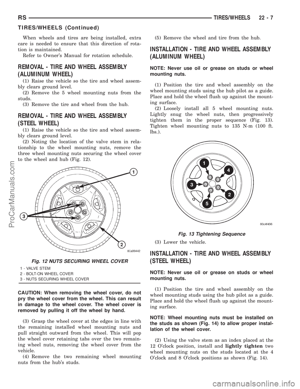
to the wheel and hub (Fig. 12).
CAUTION: When removing the wheel cover, do not
pry the wheel cover from the wheel. This can result
in damage to the wheel cover. The wheel cover is
removed by pulling it off the wheel by hand.
(3) Grasp the wheel cover at the edges in line with
the remaining installed wheel mounting nuts and
pull straight outward from the wheel. This will pop
the wheel cover retaining tabs over the two remain-
ing wheel nuts, removing the wheel cover from the
vehicle.
(4) Remove the two remaining wheel mounting
nuts from the hub's studs.(5) Remove the wheel and tire from the hub.
INSTALLATION - TIRE AND WHEEL ASSEMBLY
(ALUMINUM WHEEL)
NOTE: Never use oil or grease on studs or wheel
mounting nuts.
(1) Position the tire and wheel assembly on the
wheel mounting studs using the hub pilot as a guide.
Place and hold the wheel flush up against the mount-
ing surface.
(2) Loosely install all 5 wheel mounting nuts.
Lightly snug the wheel nuts, then progressively
tighten them in the proper sequence (Fig. 13).
Tighten wheel mounting nuts to 135 N´m (100 ft.
lbs.).
(3) Lower the vehicle.
INSTALLATION - TIRE AND WHEEL ASSEMBLY
(STEEL WHEEL)
NOTE: Never use oil or grease on studs or wheel
mounting nuts.
(1) Position the tire and wheel assembly on the
wheel mounting studs using the hub pilot as a guide.
Place and hold the wheel flush up against the mount-
ing surface.
NOTE: Wheel mounting nuts must be installed on
the studs as shown (Fig. 14) to allow proper instal-
lation of the wheel cover.
(2) Using the valve stem as an index placed at the
12 O'clock position, install andlightly tightentwo
wheel mounting nuts on the studs located at the 4
O'clock and 8 O'clock positions as shown (Fig. 14).
Fig. 12 NUTS SECURING WHEEL COVER
1 - VALVE STEM
2 - BOLT-ON WHEEL COVER
3 - NUTS SECURING WHEEL COVER
Fig. 13 Tightening Sequence
RSTIRES/WHEELS22-7
TIRES/WHEELS (Continued)
ProCarManuals.com
Page 2084 of 2321
(8) Install center roller channel end cover (Fig. 16).
(9) Install center stop on sliding door. (Refer to 23
- BODY/DOORS - SLIDING/STOP BUMPER -
INSTALLATION)
(10) Place upper roller stop bumper in position on
upper roller arm.
(11) Install screw to hold upper roller arm stop
bumper to upper roller arm (Fig. 14).
(12) Remove masking tape from body surfaces.
(13) Verify door operation and fit. Adjust as neces-
sary. (Refer to 23 - BODY/DOORS - SLIDING/SLID-
ING DOOR - ADJUSTMENTS)
SLIDING DOOR ADJUSTMENTS
NOTE: For power sliding door procedures refer to
POWER SLIDING DOOR SYSTEM in the ELECTRI-
CAL section.
PRELIMINARY CHECKS
(1) Close the sliding door, visually checking C-post
striker alignment entry into latch. Striker at this
point must not affect alignment. Striker should go
straight into the latching mechanism.
(2) On vehicles with left sliding doors, check the
fuel door blocker striker entry into latch. Striker at
this point must not affect alignment.
(3) Check C-post and B-post for door to aperture
gaps and door to door gaps. All gaps should be 5 mm
1 mm.
(4) Check door for height using character lines as
a reference. Also check roof contour as a controlling
factor.
Using the procedures noted below, adjust the side
door in the order the individual steps are called out.
DOOR FLUSHNESS ADJUSTMENT
(1) Check sliding door flushness at the C-pillar
striker.
(2) Adjust the C-pillar striker in or out untill the
door is flush.
(3) Check upper B-pillar flushness to A-pillar
cover.
(4) Loosen one nut on upper hinge and adjust door
in or out untill the door is flush.
(5) Check flushness at upper C-pillar.
(6) If upper C-pillar flushness is out of specifica-
tion use a heavy rubber malet on the door assembly
until door is in spec.
DOOR GAP ADJUSTMENT - UP/DOWN
UP/DOWN ADJUSTMENT
(1) Visually inspect the sliding door for fitting low
at the top of the door by checking the alignment of
the top contour of the door to the quarter panel.(2) Fully open the sliding door.
(3) Verify that all center hinge bolts are tight.
(4) Adjust the rear of the sliding door up by turn-
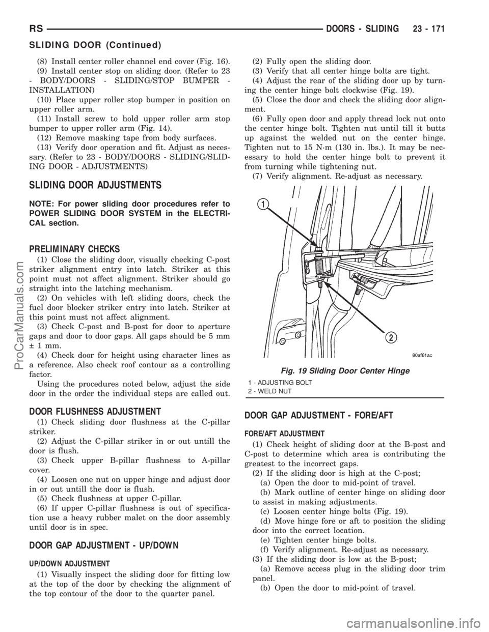
ing the center hinge bolt clockwise (Fig. 19).
(5) Close the door and check the sliding door align-
ment.
(6) Fully open door and apply thread lock nut onto
the center hinge bolt. Tighten nut until till it butts
up against the welded nut on the center hinge.
Tighten nut to 15 N´m (130 in. lbs.). It may be nec-
essary to hold the center hinge bolt to prevent it
from turning while tightening nut.
(7) Verify alignment. Re-adjust as necessary.
DOOR GAP ADJUSTMENT - FORE/AFT
FORE/AFT ADJUSTMENT
(1) Check height of sliding door at the B-post and
C-post to determine which area is contributing the
greatest to the incorrect gaps.
(2) If the sliding door is high at the C-post;
(a) Open the door to mid-point of travel.
(b) Mark outline of center hinge on sliding door
to assist in making adjustments.
(c) Loosen center hinge bolts (Fig. 19).
(d) Move hinge fore or aft to position the sliding
door into the correct location.
(e) Tighten center hinge bolts.
(f) Verify alignment. Re-adjust as necessary.
(3) If the sliding door is low at the B-post;
(a) Remove access plug in the sliding door trim
panel.
(b) Open the door to mid-point of travel.
Fig. 19 Sliding Door Center Hinge
1 - ADJUSTING BOLT
2 - WELD NUT
RSDOORS - SLIDING23 - 171
SLIDING DOOR (Continued)
ProCarManuals.com
Page 2155 of 2321
UNDER SEAT STORAGE BIN
GUIDE
REMOVAL
(1) Remove under seat storage bin. (Refer to 23 -
BODY/SEATS/UNDER SEAT STORAGE BIN -
REMOVAL).
(2) Remove screws attaching storage bin track
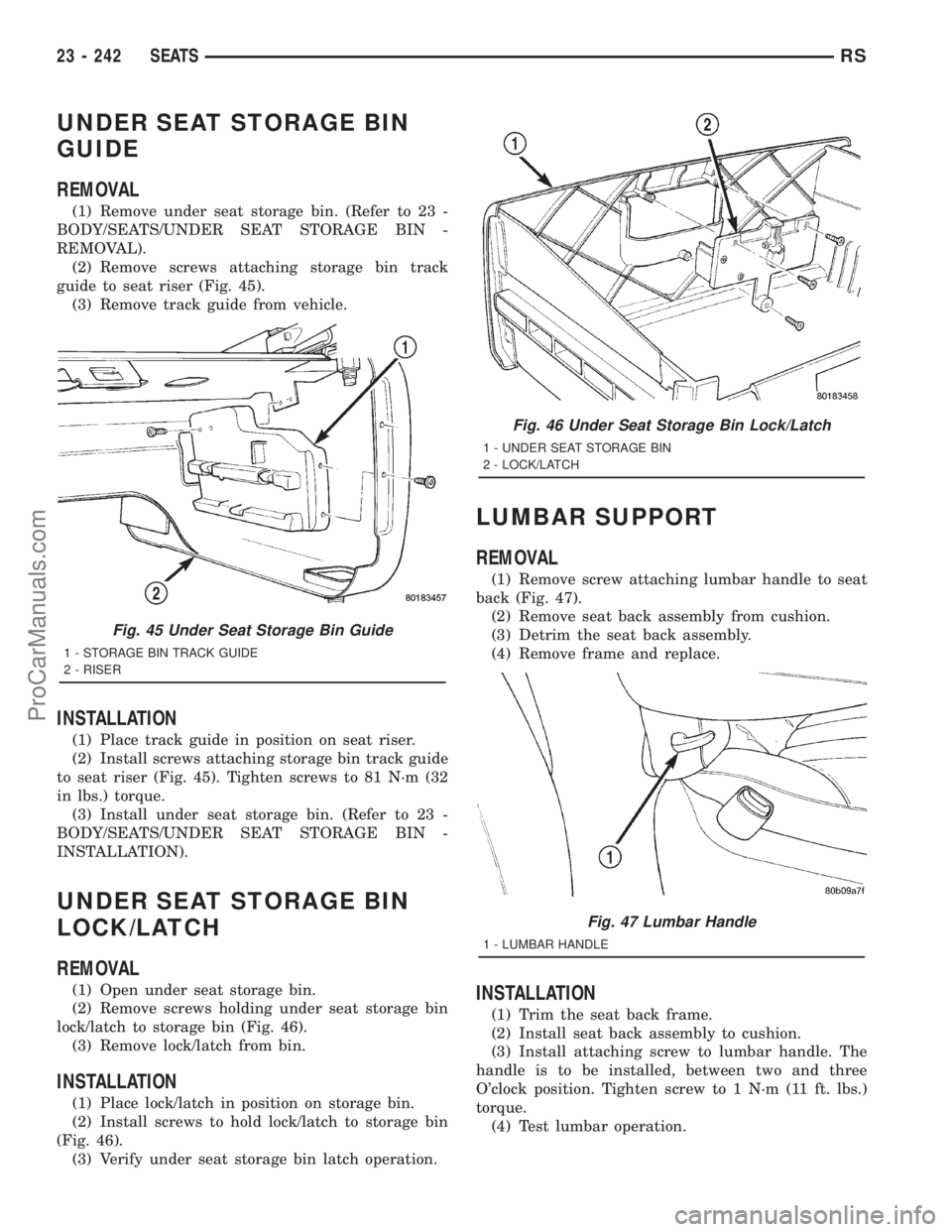
guide to seat riser (Fig. 45).
(3) Remove track guide from vehicle.
INSTALLATION
(1) Place track guide in position on seat riser.
(2) Install screws attaching storage bin track guide
to seat riser (Fig. 45). Tighten screws to 81 N´m (32
in lbs.) torque.
(3) Install under seat storage bin. (Refer to 23 -
BODY/SEATS/UNDER SEAT STORAGE BIN -
INSTALLATION).
UNDER SEAT STORAGE BIN
LOCK/LATCH
REMOVAL
(1) Open under seat storage bin.
(2) Remove screws holding under seat storage bin
lock/latch to storage bin (Fig. 46).
(3) Remove lock/latch from bin.
INSTALLATION
(1) Place lock/latch in position on storage bin.
(2) Install screws to hold lock/latch to storage bin
(Fig. 46).
(3) Verify under seat storage bin latch operation.
LUMBAR SUPPORT
REMOVAL
(1) Remove screw attaching lumbar handle to seat
back (Fig. 47).
(2) Remove seat back assembly from cushion.
(3) Detrim the seat back assembly.
(4) Remove frame and replace.
INSTALLATION
(1) Trim the seat back frame.
(2) Install seat back assembly to cushion.
(3) Install attaching screw to lumbar handle. The
handle is to be installed, between two and three
O'clock position. Tighten screw to 1 N´m (11 ft. lbs.)
torque.
(4) Test lumbar operation.
Fig. 45 Under Seat Storage Bin Guide
1 - STORAGE BIN TRACK GUIDE
2 - RISER
Fig. 46 Under Seat Storage Bin Lock/Latch
1 - UNDER SEAT STORAGE BIN
2 - LOCK/LATCH
Fig. 47 Lumbar Handle
1 - LUMBAR HANDLE
23 - 242 SEATSRS
ProCarManuals.com
Page 2228 of 2321
OPERATION
The compressor is driven by the engine through an
electric clutch, drive pulley and belt arrangement.
The compressor is lubricated by refrigerant oil that is
circulated throughout the refrigerant system with the
refrigerant. The compressor draws in low-pressure
refrigerant vapor from the evaporator through its
suction port. It then compresses the refrigerant into
a high-pressure, high-temperature refrigerant vapor.
The compressor pumps high-pressure refrigerant
vapor to the condenser through the compressor dis-
charge port. The mechanical high pressure relief
valve is designed to vent refrigerant from the system
to protect against damage to the compressor or other
system components, caused by condenser air flow
restrictions or an overcharge of refrigerant. The valve
only vents enough refrigerant to reduce the system
pressure, then re-seats itself. The valve opens at a
discharge pressure of 3445 to 4135 kPA (500 to 600
psi) or above, and closes when a minimum discharge
pressure of 2756 kPa (400 psi) is reached.
DIAGNOSIS AND TESTING - COMPRESSOR
NOISE
Excessive noise while the air conditioning compres-
sor is operating can be caused by loose compressor
mounts, a loose compressor clutch, or high operating
pressures in the refrigerant system. Verify compres-
sor drive belt condition, proper compressor mounting,
correct refrigerant charge level, and compressor head
pressure before compressor repair is performed.
With the close tolerances within the compressor, it
is possible to experience a temporary lockup. The
longer the compressor is inactive, the more likely the
condition is to occur. This condition is the result of
normal refrigerant migration within the refrigerant
system caused by ambient temperature changes. The
refrigerant migration may wash the refrigerant oil
out of the compressor.
NOTE: Prior to a vehicle being removed from ser-
vice or stored for more than two weeks, the com-
pressor should be operated to ensure adequate
refrigerant oil distribution throughout the system
components. Turn on the air conditioner for a min-
imum of five minutes with outside air and the high-
est blower speed selected.
BELT NOISE
If the compressor drive belt slips at initial start-up,
it does not necessarily mean the compressor has
failed. The following procedure can be used to iden-
tify a compressor drive belt noise problem.
²Start the vehicle and run at idle.²Turn the air conditioner On and listen for belt
squeal.
²If belt squeal is heard, turn the air conditioner
Off immediately.
If the belt squeal stops when the air conditioner is
turned Off, perform the following repair procedures.
(1) Using an appropriate sized oil filter wrench or
a strap wrench, grasp the outer diameter of the com-
pressor clutch hub. While facing the compressor,
rotate the hub clockwise, then counterclockwise. If
the hub rotates, proceed to the next step. If the hub
will not rotate, the compressor is internally damaged,
and must be replaced.
(2) Turn the hub clockwise five complete revolu-
tions and remove the tool.
(3) Start the vehicle and run at idle.
(4) Turn the air conditioner On. Observe the com-
pressor and the system for normal operation, noting
cooling performance and noise levels. Operate for five
minutes before turning the air conditioner Off. If
acceptable cooling performance is observed during
compressor operation, the compressor does not need
to be replaced.
(5) Inspect the drive belt for wear, damage, and
proper tension. (Refer to 7 - COOLING/ACCESSORY
DRIVE/DRIVE BELTS - DIAGNOSIS AND TEST-
ING).
REMOVAL - COMPRESSOR
WARNING: REFER TO THE APPLICABLE WARN-
INGS AND CAUTIONS FOR THIS SYSTEM BEFORE
PERFORMING THE FOLLOWING OPERATION.
(Refer to 24 - HEATING & AIR CONDITIONING/
PLUMBING - FRONT - WARNING - A/C PLUMBING)
and (Refer to 24 - HEATING & AIR CONDITIONING/
PLUMBING - FRONT - CAUTION - A/C PLUMBING).
(1) Recover the refrigerant from the refrigerant
system. (Refer to 24 - HEATING & AIR CONDI-
TIONING/PLUMBING - FRONT/REFRIGERANT -
STANDARD PROCEDURE - REFRIGERANT
RECOVERY).
(2) Disconnect and isolate the battery negative
cable.
(3) Remove the nut that secures the suction line
fitting to the top of the compressor.
(4) Disconnect the suction line fitting from the
compressor suction port.
(5) Remove the seal from the suction line fitting
and discard.
(6) Install plugs in, or tape over the opened suc-
tion line fitting and the compressor suction port.
(7) Remove the nut that secures the discharge line
fitting to the top of the compressor.
(8) Disconnect the discharge line fitting from the
compressor discharge port.
RSPLUMBING - FRONT24-65
COMPRESSOR (Continued)
ProCarManuals.com