2001 DODGE TOWN AND COUNTRY clock
[x] Cancel search: clockPage 1530 of 2321
TEST ONE (SELECTOR IN 1)
(1) Attach gauges to line and low-reverse ports.
(2) Operate engine at 1000 rpm for test.
(3) Move selector lever on transaxle all the way
rearward (1 position).
(4) Read pressures on both gauges as throttle lever
on transaxle is moved from full clockwise position to
full counterclockwise position.
(5) Line pressure should read 52 to 58 psi with
throttle lever clockwise. Pressure should gradually
increase to 80 to 88 psi.as lever is moved counter-
clockwise.
(6) Low/reverse pressure should read the same as
line pressure, within 3 psi.
(7) This tests pump output, pressure regulation,
and condition of rear clutch and rear servo hydraulic
circuits.
TEST TWO (SELECTOR IN 2)
(1) Attach one gauge to line pressure port, and tee
another gauge into lower cooler line fitting. This will
allow lubrication pressure readings to be taken.
(2) Operate engine at 1000 rpm for test.
(3) Move selector lever on transaxle one detent for-
ward from full rearward position. This is selector 2
position.
(4) Read pressures on both gauges as throttle lever
on transaxle is moved from full clockwise position to
full counterclockwise position.
(5) Line pressure should read 52 to 58 psi with
throttle lever clockwise. Pressure should gradually
increase to 80 to 88 psi. as lever is moved counter-
clockwise.
(6) Lubrication pressure should be 10 to 25 psi
with lever clockwise and 10 to 35 psi with lever at
full counterclockwise.(7) This tests pump output, pressure regulation,
and condition of rear clutch and lubrication hydraulic
circuits.
TEST THREE (SELECTOR IN D)
(1) Attach gauges to line and kickdown release
ports.
(2) Operate engine at 1600 rpm for test.
(3) Move selector lever on transaxle two detents
forward from full rearward position. This is selector
D position.
(4) Read pressures on both gauges as throttle lever
on transaxle is moved from full clockwise to the full
counterclockwise position.
(5) Line pressure should read 52 to 58 psi with
throttle lever clockwise. Pressure should gradually
increase to 80 to 88 psi. as lever is moved counter-
clockwise.
(6) Kickdown release is pressurized only in direct
drive and should be same as line pressure within 3
psi, up to kickdown point.
(7) This tests pump output, pressure regulation,
and condition of rear clutch, front clutch, and
hydraulic circuits.
TEST FOUR (SELECTOR IN REVERSE)
(1) Attach 300 psi gauge (C-3292SP) to low-reverse
port.
(2) Operate engine at 1600 rpm for test.
(3) Move selector lever on transaxle four detents
forward from full rearward position. This is selector
R position.
(4) Low/reverse pressure should read 180 to 220
psi with throttle lever clockwise. Pressure should
gradually increase to 260 to 300 psi. as lever is
moved counterclockwise.
(5) This tests pump output, pressure regulation,
and condition of front clutch and rear servo hydraulic
circuits.
(6) Move selector lever on transaxle to D position
to check that low/reverse pressure drops to zero.
(7) This tests for leakage into rear servo, due to
case porosity, which can cause reverse band burn out.
TEST RESULT INDICATIONS
(1) If proper line pressure, minimum to maximum,
is found in any one test, the pump and pressure reg-
ulator are working properly.
(2) Low pressure in D, 1, and 2 but correct pres-
sure in R, indicates rear clutch circuit leakage.
(3) Low pressure in D and R, but correct pressure
in 1 indicates front clutch circuit leakage.
(4) Low pressure in R and 1, but correct pressure
in 2 indicates rear servo circuit leakage.
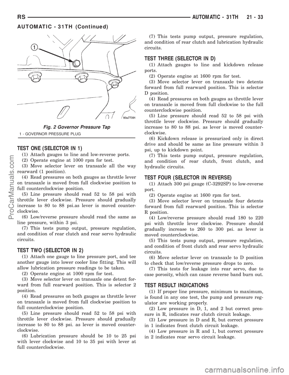
Fig. 2 Governor Pressure Tap
1 - GOVERNOR PRESSURE PLUG
RSAUTOMATIC - 31TH21-33
AUTOMATIC - 31TH (Continued)
ProCarManuals.com
Page 1619 of 2321
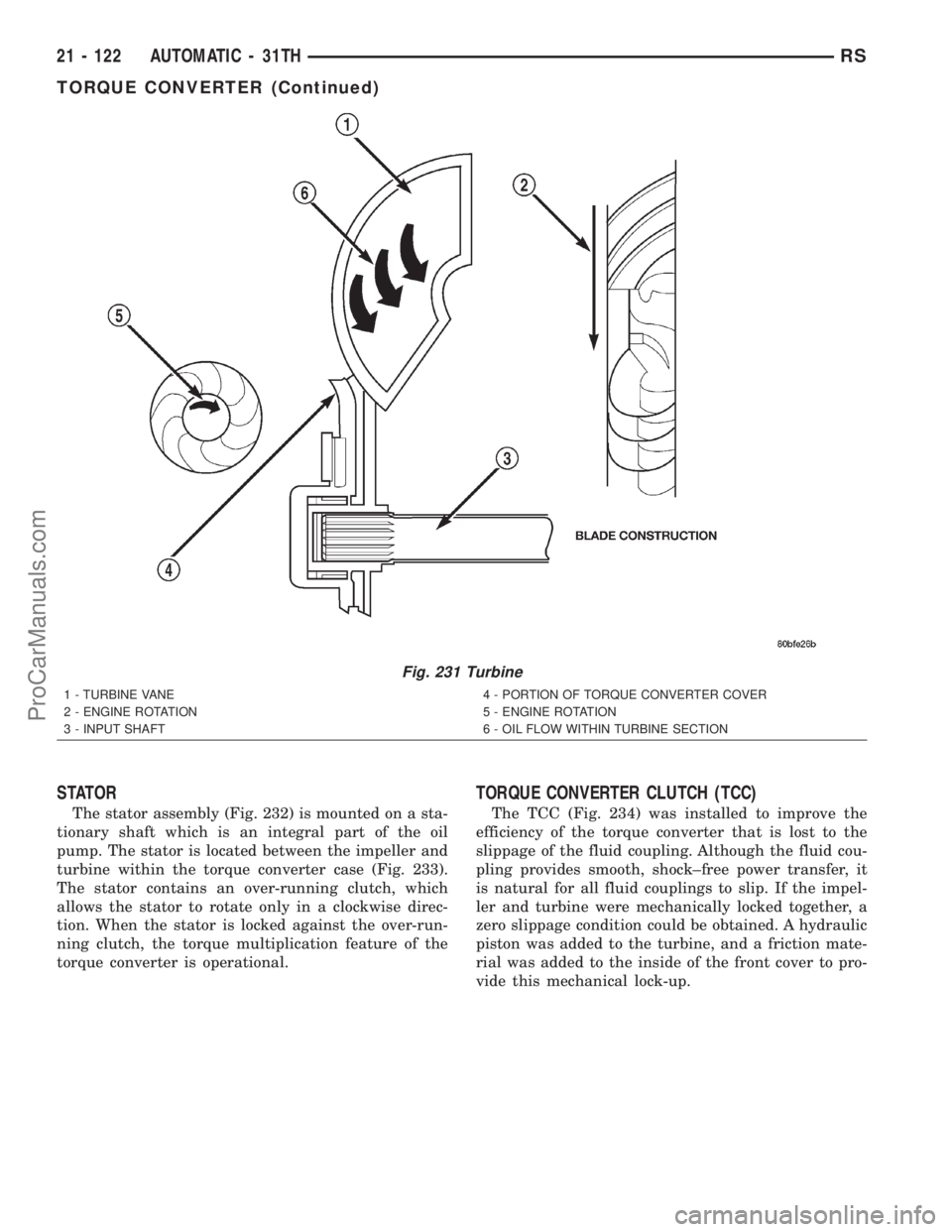
STATOR
The stator assembly (Fig. 232) is mounted on a sta-
tionary shaft which is an integral part of the oil
pump. The stator is located between the impeller and
turbine within the torque converter case (Fig. 233).
The stator contains an over-running clutch, which
allows the stator to rotate only in a clockwise direc-
tion. When the stator is locked against the over-run-
ning clutch, the torque multiplication feature of the
torque converter is operational.
TORQUE CONVERTER CLUTCH (TCC)
The TCC (Fig. 234) was installed to improve the
efficiency of the torque converter that is lost to the
slippage of the fluid coupling. Although the fluid cou-
pling provides smooth, shock±free power transfer, it
is natural for all fluid couplings to slip. If the impel-
ler and turbine were mechanically locked together, a
zero slippage condition could be obtained. A hydraulic
piston was added to the turbine, and a friction mate-
rial was added to the inside of the front cover to pro-
vide this mechanical lock-up.
Fig. 231 Turbine
1 - TURBINE VANE
2 - ENGINE ROTATION
3 - INPUT SHAFT4 - PORTION OF TORQUE CONVERTER COVER
5 - ENGINE ROTATION
6 - OIL FLOW WITHIN TURBINE SECTION
21 - 122 AUTOMATIC - 31THRS
TORQUE CONVERTER (Continued)
ProCarManuals.com
Page 1620 of 2321
OPERATION
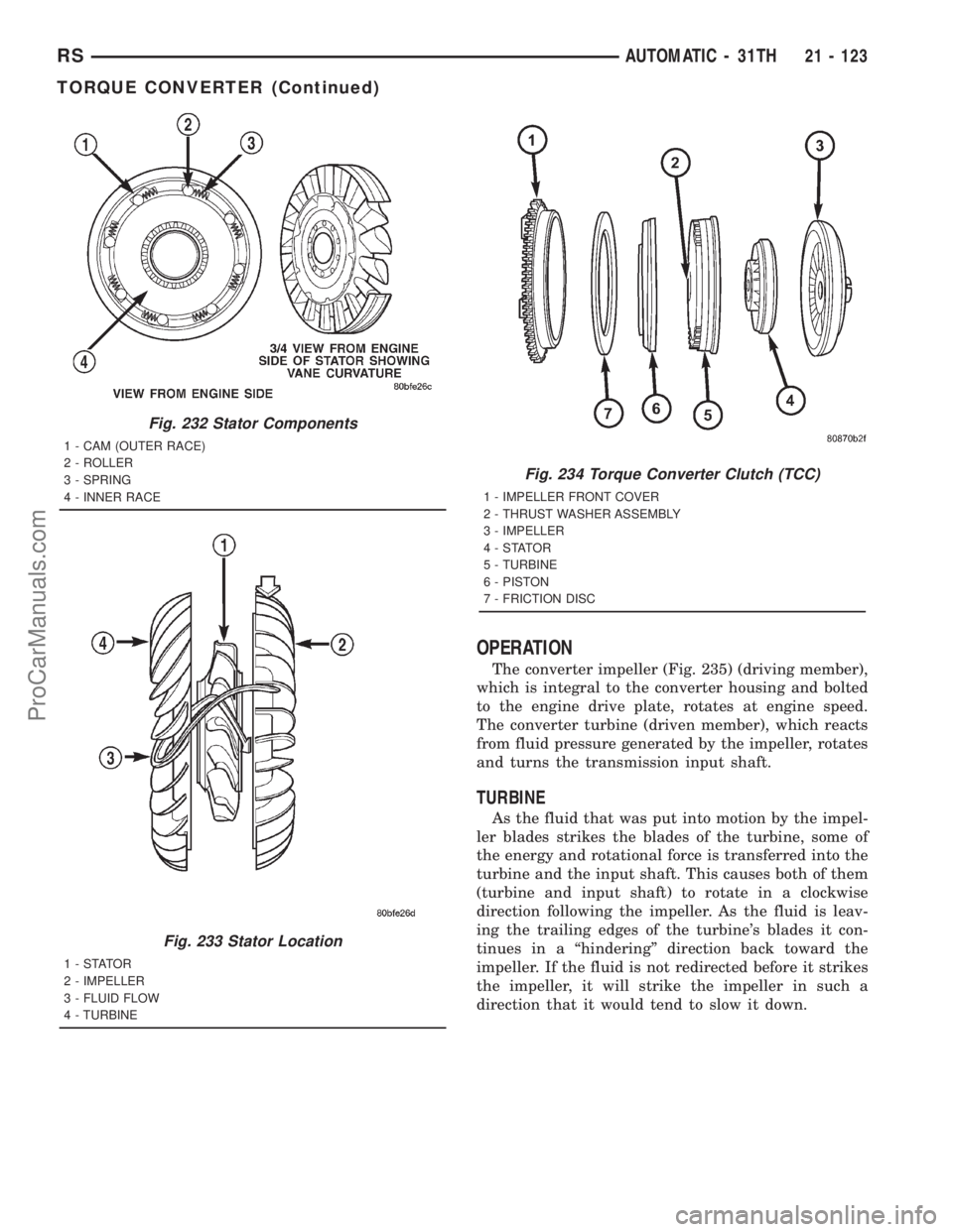
The converter impeller (Fig. 235) (driving member),
which is integral to the converter housing and bolted
to the engine drive plate, rotates at engine speed.
The converter turbine (driven member), which reacts
from fluid pressure generated by the impeller, rotates
and turns the transmission input shaft.
TURBINE
As the fluid that was put into motion by the impel-
ler blades strikes the blades of the turbine, some of
the energy and rotational force is transferred into the
turbine and the input shaft. This causes both of them
(turbine and input shaft) to rotate in a clockwise
direction following the impeller. As the fluid is leav-
ing the trailing edges of the turbine's blades it con-
tinues in a ªhinderingº direction back toward the
impeller. If the fluid is not redirected before it strikes
the impeller, it will strike the impeller in such a
direction that it would tend to slow it down.
Fig. 232 Stator Components
1 - CAM (OUTER RACE)
2 - ROLLER
3 - SPRING
4 - INNER RACE
Fig. 233 Stator Location
1-STATOR
2 - IMPELLER
3 - FLUID FLOW
4 - TURBINE
Fig. 234 Torque Converter Clutch (TCC)
1 - IMPELLER FRONT COVER
2 - THRUST WASHER ASSEMBLY
3 - IMPELLER
4-STATOR
5 - TURBINE
6 - PISTON
7 - FRICTION DISC
RSAUTOMATIC - 31TH21 - 123
TORQUE CONVERTER (Continued)
ProCarManuals.com
Page 1621 of 2321
STATOR
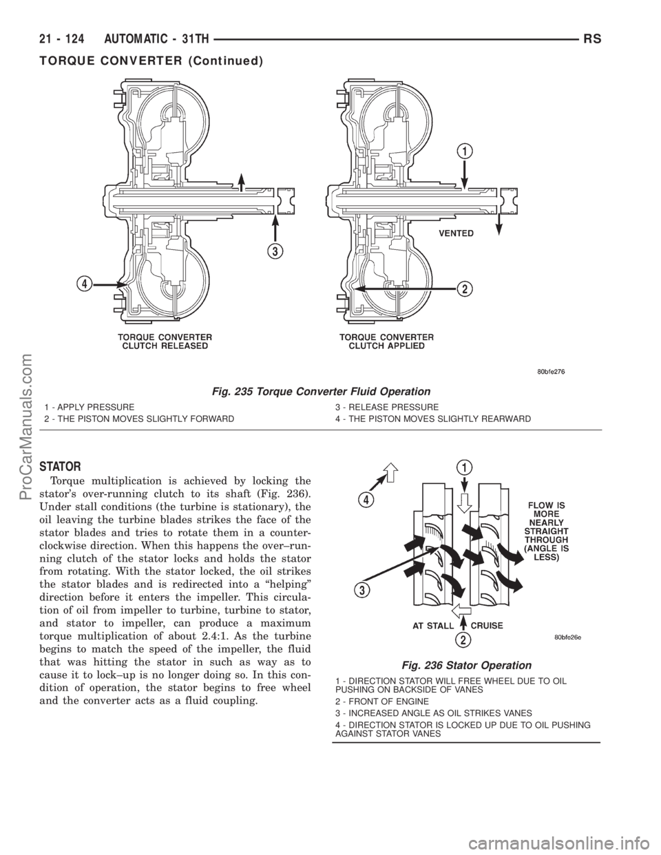
Torque multiplication is achieved by locking the
stator's over-running clutch to its shaft (Fig. 236).
Under stall conditions (the turbine is stationary), the
oil leaving the turbine blades strikes the face of the
stator blades and tries to rotate them in a counter-
clockwise direction. When this happens the over±run-
ning clutch of the stator locks and holds the stator
from rotating. With the stator locked, the oil strikes
the stator blades and is redirected into a ªhelpingº
direction before it enters the impeller. This circula-
tion of oil from impeller to turbine, turbine to stator,
and stator to impeller, can produce a maximum
torque multiplication of about 2.4:1. As the turbine
begins to match the speed of the impeller, the fluid
that was hitting the stator in such as way as to
cause it to lock±up is no longer doing so. In this con-
dition of operation, the stator begins to free wheel
and the converter acts as a fluid coupling.
Fig. 235 Torque Converter Fluid Operation
1 - APPLY PRESSURE
2 - THE PISTON MOVES SLIGHTLY FORWARD3 - RELEASE PRESSURE
4 - THE PISTON MOVES SLIGHTLY REARWARD
Fig. 236 Stator Operation
1 - DIRECTION STATOR WILL FREE WHEEL DUE TO OIL
PUSHING ON BACKSIDE OF VANES
2 - FRONT OF ENGINE
3 - INCREASED ANGLE AS OIL STRIKES VANES
4 - DIRECTION STATOR IS LOCKED UP DUE TO OIL PUSHING
AGAINST STATOR VANES
21 - 124 AUTOMATIC - 31THRS
TORQUE CONVERTER (Continued)
ProCarManuals.com
Page 1628 of 2321
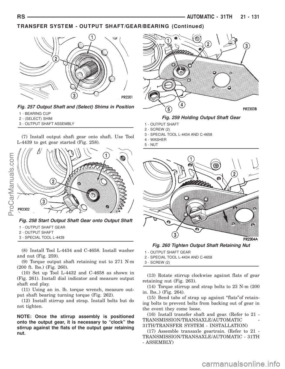
(7) Install output shaft gear onto shaft. Use Tool
L-4439 to get gear started (Fig. 258).
(8) Install Tool L-4434 and C-4658. Install washer
and nut (Fig. 259).
(9) Torque output shaft retaining nut to 271 N´m
(200 ft. lbs.) (Fig. 260).
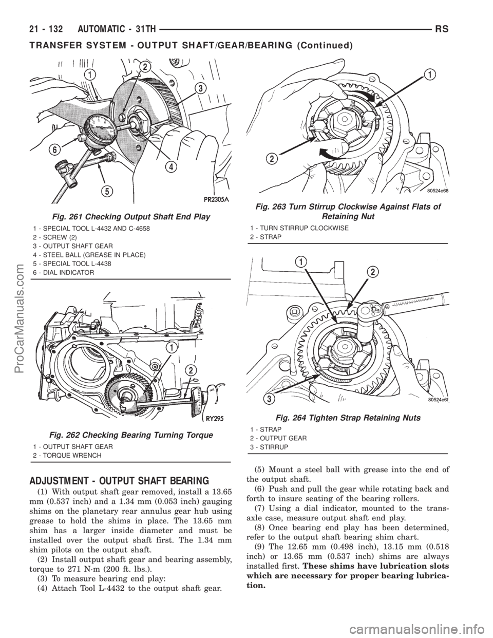
(10) Set up Tool L-4432 and C-4658 as shown in
(Fig. 261). Install dial indicator and measure output
shaft end play.
(11) Using an in. lb. torque wrench, measure out-
put shaft bearing turning torque (Fig. 262).
(12) Install stirrup and strap. Install bolts but do
not tighten.
NOTE: Once the stirrup assembly is positioned
onto the output gear, it is necessary to ªclockº the
stirrup against the flats of the output gear retaining
nut.(13) Rotate stirrup clockwise against flats of gear
retaining nut (Fig. 263).
(14) Torque stirrup and strap bolts to 23 N´m (200
in. lbs..) (Fig. 264).
(15) Bend tabs of strap up against ªflatsºof retain-
ing bolts to prevent bolts from backing out of gear in
the event they come loose.
(16) Install transfer shaft and gear. (Refer to 21 -
TRANSMISSION/TRANSAXLE/AUTOMATIC -
31TH/TRANSFER SYSTEM - INSTALLATION)
(17) Assemble transaxle geartrain. (Refer to 21 -
TRANSMISSION/TRANSAXLE/AUTOMATIC - 31TH
- ASSEMBLY)
Fig. 257 Output Shaft and (Select) Shims in Position
1 - BEARING CUP
2 - (SELECT) SHIM
3 - OUTPUT SHAFT ASSEMBLY
Fig. 258 Start Output Shaft Gear onto Output Shaft
1 - OUTPUT SHAFT GEAR
2 - OUTPUT SHAFT
3 - SPECIAL TOOL L-4439
Fig. 259 Holding Output Shaft Gear
1 - OUTPUT SHAFT
2 - SCREW (2)
3 - SPECIAL TOOL L-4434 AND C-4658
4 - WASHER
5 - NUT
Fig. 260 Tighten Output Shaft Retaining Nut
1 - OUTPUT SHAFT GEAR
2 - SPECIAL TOOL L-4434 AND C-4658
3 - SCREW (2)
RSAUTOMATIC - 31TH21 - 131
TRANSFER SYSTEM - OUTPUT SHAFT/GEAR/BEARING (Continued)
ProCarManuals.com
Page 1629 of 2321
ADJUSTMENT - OUTPUT SHAFT BEARING
(1) With output shaft gear removed, install a 13.65
mm (0.537 inch) and a 1.34 mm (0.053 inch) gauging
shims on the planetary rear annulus gear hub using
grease to hold the shims in place. The 13.65 mm
shim has a larger inside diameter and must be
installed over the output shaft first. The 1.34 mm
shim pilots on the output shaft.
(2) Install output shaft gear and bearing assembly,
torque to 271 N´m (200 ft. lbs.).
(3) To measure bearing end play:
(4) Attach Tool L-4432 to the output shaft gear.(5) Mount a steel ball with grease into the end of
the output shaft.
(6) Push and pull the gear while rotating back and
forth to insure seating of the bearing rollers.
(7) Using a dial indicator, mounted to the trans-
axle case, measure output shaft end play.
(8) Once bearing end play has been determined,
refer to the output shaft bearing shim chart.
(9) The 12.65 mm (0.498 inch), 13.15 mm (0.518
inch) or 13.65 mm (0.537 inch) shims are always
installed first.These shims have lubrication slots
which are necessary for proper bearing lubrica-
tion.
Fig. 261 Checking Output Shaft End Play
1 - SPECIAL TOOL L-4432 AND C-4658
2 - SCREW (2)
3 - OUTPUT SHAFT GEAR
4 - STEEL BALL (GREASE IN PLACE)
5 - SPECIAL TOOL L-4438
6 - DIAL INDICATOR
Fig. 262 Checking Bearing Turning Torque
1 - OUTPUT SHAFT GEAR
2 - TORQUE WRENCH
Fig. 263 Turn Stirrup Clockwise Against Flats of
Retaining Nut
1 - TURN STIRRUP CLOCKWISE
2 - STRAP
Fig. 264 Tighten Strap Retaining Nuts
1 - STRAP
2 - OUTPUT GEAR
3 - STIRRUP
21 - 132 AUTOMATIC - 31THRS
TRANSFER SYSTEM - OUTPUT SHAFT/GEAR/BEARING (Continued)
ProCarManuals.com
Page 1638 of 2321
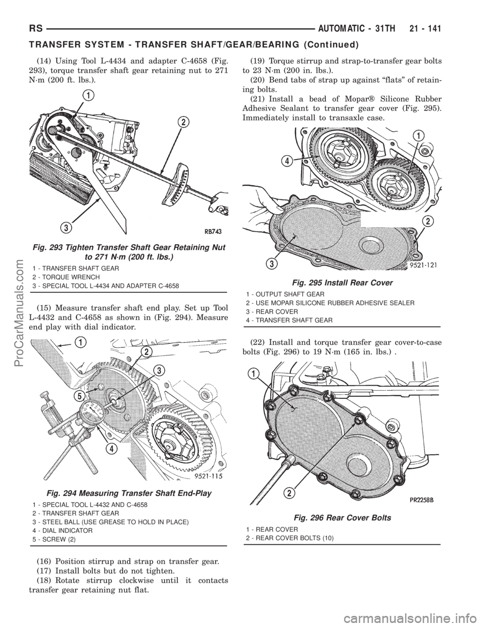
(14) Using Tool L-4434 and adapter C-4658 (Fig.
293), torque transfer shaft gear retaining nut to 271
N´m (200 ft. lbs.).
(15) Measure transfer shaft end play. Set up Tool
L-4432 and C-4658 as shown in (Fig. 294). Measure
end play with dial indicator.
(16) Position stirrup and strap on transfer gear.
(17) Install bolts but do not tighten.
(18) Rotate stirrup clockwise until it contacts
transfer gear retaining nut flat.(19) Torque stirrup and strap-to-transfer gear bolts
to 23 N´m (200 in. lbs.).
(20) Bend tabs of strap up against ªflatsº of retain-
ing bolts.
(21) Install a bead of Moparž Silicone Rubber
Adhesive Sealant to transfer gear cover (Fig. 295).
Immediately install to transaxle case.
(22) Install and torque transfer gear cover-to-case
bolts (Fig. 296) to 19 N´m (165 in. lbs.) .
Fig. 293 Tighten Transfer Shaft Gear Retaining Nut
to 271 N´m (200 ft. lbs.)
1 - TRANSFER SHAFT GEAR
2 - TORQUE WRENCH
3 - SPECIAL TOOL L-4434 AND ADAPTER C-4658
Fig. 294 Measuring Transfer Shaft End-Play
1 - SPECIAL TOOL L-4432 AND C-4658
2 - TRANSFER SHAFT GEAR
3 - STEEL BALL (USE GREASE TO HOLD IN PLACE)
4 - DIAL INDICATOR
5 - SCREW (2)
Fig. 295 Install Rear Cover
1 - OUTPUT SHAFT GEAR
2 - USE MOPAR SILICONE RUBBER ADHESIVE SEALER
3 - REAR COVER
4 - TRANSFER SHAFT GEAR
Fig. 296 Rear Cover Bolts
1 - REAR COVER
2 - REAR COVER BOLTS (10)
RSAUTOMATIC - 31TH21 - 141
TRANSFER SYSTEM - TRANSFER SHAFT/GEAR/BEARING (Continued)
ProCarManuals.com
Page 1654 of 2321
HYDRAULIC CONTROL PRESSURE
ADJUSTMENTS
LINE PRESSURE
An incorrect throttle pressure setting will cause
incorrect line pressure readings even though line
pressure adjustment is correct. Always inspect and
correct throttle pressure adjustment before adjusting
the line pressure.
The approximate adjustment for line pressure is
1-5/16 inches, measured from valve body to inner
edge of adjusting nut. However, due to manufactur-
ing tolerances, the adjustment can be varied to
obtain specified line pressure.
The adjusting screw may be turned with an Allen
wrench. One complete turn of adjusting screw
changes closed throttle line pressure approximately
1-2/3 psi. Turning adjusting screw counterclockwise
increases pressure, and clockwise decreases pressure.
THROTTLE PRESSURE
Throttle pressures cannot be tested accurately;
therefore, the adjustment should be measured if a
malfunction is evident.
(1) Insert gauge pin of Tool C-3763 between the
throttle lever cam and kickdown valve.
(2) By pushing in on tool, compress kickdown
valve against its spring so throttle valve is com-
pletely bottomed inside the valve body.
(3) While compressing spring, turn throttle lever
stop screw with adapter C-4553. Turn until head of
screw touches throttle lever tang, with throttle lever
cam touching tool and throttle valve bottomed. Be
sure adjustment is made with spring fully com-
pressed and valve bottomed in the valve body.
VEHICLE SPEED SENSOR/
PINION GEAR
REMOVAL
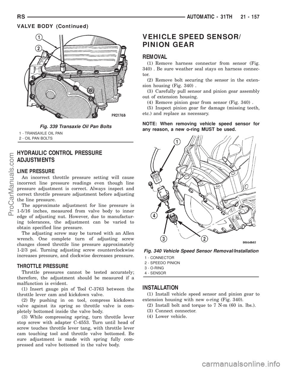
(1) Remove harness connector from sensor (Fig.
340) . Be sure weather seal stays on harness connec-
tor.
(2) Remove bolt securing the sensor in the exten-
sion housing (Fig. 340) .
(3) Carefully pull sensor and pinion gear assembly
out of extension housing.
(4) Remove pinion gear from sensor (Fig. 340) .
(5) Inspect pinion gear for damage (missing teeth,
etc.) and replace as necessary.
NOTE: When removing vehicle speed sensor for
any reason, a new o-ring MUST be used.
INSTALLATION
(1) Install vehicle speed sensor and pinion gear to
extension housing with new o-ring (Fig. 340).
(2) Install bolt and torque to 7 N´m (60 in. lbs.).
(3) Connect connector.
(4) Lower vehicle.
Fig. 339 Transaxle Oil Pan Bolts
1 - TRANSAXLE OIL PAN
2 - OIL PAN BOLTS
Fig. 340 Vehicle Speed Sensor Removal/Installation
1 - CONNECTOR
2 - SPEEDO PINION
3 - O-RING
4 - SENSOR
RSAUTOMATIC - 31TH21 - 157
VALVE BODY (Continued)
ProCarManuals.com