2001 DODGE TOWN AND COUNTRY torque
[x] Cancel search: torquePage 209 of 2321
WHEEL CYLINDERS
REMOVAL
(1) Using a brake pedal depressor, move and
secure brake pedal to a position past its first 1 inch
of travel. This will prevent brake fluid from draining
out of master cylinder when brake tube is remove
from wheel cylinder.
(2) Raise vehicle. (Refer to LUBRICATION &
MAINTENANCE/HOISTING - STANDARD PROCE-
DURE).
(3) Remove wheel and tire assembly.
(4) Disconnect brake tube from rear of wheel cylin-
der. Cap open ends
(5) Remove brake drum.
(6) Remove brake shoes from brake support plate
(Discard if contaminated).(Refer to 5 - BRAKES/HY-
DRAULIC/MECHANICAL/BRAKE PADS/SHOES -
REMOVAL)
(7) Remove the 2 bolts attaching the wheel cylin-
der to the brake support plate.
(8) Remove the wheel cylinder from the brake sup-
port plate.
INSPECTION
With brake drums removed, inspect the wheel cyl-
inder boots for evidence of a brake fluid leak. Visu-
ally check the boots for cuts, tears, or heat cracks. If
any of these conditions exist, the wheel cylinders
should be completely cleaned, inspected and new
parts installed.
If a wheel cylinder is leaking and the brake lining
material is saturated with brake fluid, the brake
shoes must be replaced.
INSTALLATION
(1) Apply sealant such as Mopar Gasket-In-A-Tube
or equivalent around the wheel cylinder opening in
the brake support plate.
(2) Install wheel cylinder onto brake support.
Install and tighten the wheel cylinder to brake sup-
port plate attaching bolts to 8 N´m (75 in. lbs.)
torque.
(3) Install brake tube into wheel cylinder. Tighten
tube nut to a torque of 17 N´m (145 in. lbs.) torque.
(4) Install the rear brake shoes on the brake sup-
port plate. (Refer to 5 - BRAKES/HYDRAULIC/ME-
CHANICAL/BRAKE PADS/SHOES -
INSTALLATION).
(5) Install brake drum.
(6) Install wheel and tire. Install and tighten
wheel lug nuts to 135 N´m (100 ft. lbs.).
(7) Adjust drum brake shoes. (Refer to 5 -
BRAKES/HYDRAULIC/MECHANICAL/BRAKE
PADS/SHOES - ADJUSTMENTS)
(8) Remove brake pedal depressor tool.(9) Bleed the brake system as necessary. (Refer to
5 - BRAKES - BASE - STANDARD PROCEDURE).
(10) Lower vehicle.
PARKING BRAKE
DESCRIPTION
The parking brake system is operated by a foot
operated parking brake lever. The parking brake
lever is mounted on the body of the vehicle to the left
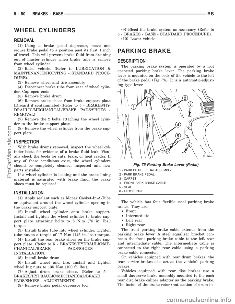
of the brake pedal (Fig. 75). It is a automatic-adjust-
ing type lever.
The vehicle has four flexible steel parking brake
cables. They are:
²Front
²Intermediate
²Left rear
²Right rear
The front parking brake cable extends from the
parking brake lever. A steel equalizer bracket con-
nects the front parking brake cable to the left rear
and intermediate cable. The intermediate cable is
connected to the right rear cable using a parking
brake cable connector.
On vehicles equipped with rear drum brakes, the
rear service brakes also act as the vehicle's parking
brakes.
Vehicles equipped with rear disc brakes use a
small duo-servo brake assembly mounted to the each
rear disc brake caliper adapter as the parking brake.
The inside of the brake rotor (hat section of drum-in-
Fig. 75 Parking Brake Lever (Pedal)
1 - PARK BRAKE PEDAL ASSEMBLY
2 - PARK BRAKE PEDAL
3 - CARPET
4 - FRONT PARK BRAKE CABLE
5 - SEAL
6 - FLOOR PAN
5 - 50 BRAKES - BASERS
ProCarManuals.com
Page 217 of 2321
INSTALLATION
(1) Install the trailing brake shoe on the adapter.
NOTE: When the hold down pin is installed, the
long part of the hold down pin is to be positioned
strait up and down. This will ensure that the hold
down pin is correctly engaged with the adapter.
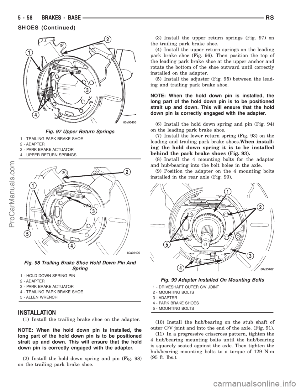
(2) Install the hold down spring and pin (Fig. 98)
on the trailing park brake shoe.(3) Install the upper return springs (Fig. 97) on
the trailing park brake shoe.
(4) Install the upper return springs on the leading
park brake shoe (Fig. 96). Then position the top of
the leading park brake shoe at the upper anchor and
rotate the bottom of the shoe outward until correctly
installed on the adapter.
(5) Install the adjuster (Fig. 95) between the lead-
ing and trailing park brake shoe.
NOTE: When the hold down pin is installed, the
long part of the hold down pin is to be positioned
strait up and down. This will ensure that the hold
down pin is correctly engaged with the adapter.
(6) Install the hold down spring and pin (Fig. 94)
on the leading park brake shoe.
(7) Install the lower return spring (Fig. 93) on the
leading and trailing park brake shoes.When install-
ing the hold down spring it is to be installed
behind the park brake shoes (Fig. 93).
(8) Install the 4 mounting bolts for the adapter
and hub/bearing into the bolt holes in the axle.
(9) Position the adapter on the 4 mounting bolts
installed in the rear axle (Fig. 99).
(10) Install the hub/bearing on the stub shaft of
outer C/V joint and into the end of the axle. (Fig. 91).
(11) In a progressive crisscross pattern, tighten the
4 hub/bearing mounting bolts until the hub/bearing
is squarely seated against the axle. Then tighten the
hub/bearing mounting bolts to a torque of 129 N´m
(95 ft. lbs.).
Fig. 97 Upper Return Springs
1 - TRAILING PARK BRAKE SHOE
2 - ADAPTER
3 - PARK BRAKE ACTUATOR
4 - UPPER RETURN SPRINGS
Fig. 98 Trailing Brake Shoe Hold Down Pin And
Spring
1 - HOLD DOWN SPRING PIN
2 - ADAPTER
3 - PARK BRAKE ACTUATOR
4 - TRAILING PARK BRAKE SHOE
5 - ALLEN WRENCHFig. 99 Adapter Installed On Mounting Bolts
1 - DRIVESHAFT OUTER C/V JOINT
2 - MOUNTING BOLTS
3 - ADAPTER
4 - PARK BRAKE SHOES
5 - MOUNTING BOLTS
5 - 58 BRAKES - BASERS
SHOES (Continued)
ProCarManuals.com
Page 218 of 2321

(12) Install the wheel speed sensor on the hub/
bearing and adapter. Install the wheel speed sensor
attaching bolt (Fig. 89). Tighten the wheel speed sen-
sor attaching bolt to a torque of 12 N´m (105 in. lbs).
(13) Install the park brake cable into its mounting
hole in the adapter.Be sure all the locking tabs
on the park brake cable retainer are expanded
out to ensure the cable will not pull out of the
adapter.
(14) Install the end of the park brake cable on the
park brake actuator lever (Fig. 87).
NOTE: The horseshoe clip must be installed and
installed properly when the park brake cable is
installed in the adapter. The purpose of the horse-
shoe clip is to prevent park brake cable retainer
from moving in the adapter. If horseshoe clip is not
installed the park brake cable retainer will rattle in
the adapter.
(15) Install aNEWhorseshoe clip on the park
brake cable retainer (Fig. 87). The horseshoe clip is
installed between the retainer for the park brake
cable and the adapter. Horseshoe clip must be
installed with the curved end of the clip pointing
straight up and the edge of the curved end facing
toward the rear of the vehicle (Fig. 87).
(16) Remove the locking pliers (Fig. 83) from the
front park brake cable.
(17) Adjust the park brake drum-in-hat brake
shoes. (Refer to 5 - BRAKES/PARKING BRAKE/
SHOES - ADJUSTMENTS).
(18) Install the rotor on the hub/bearing.
(19) Carefully lower caliper and brake shoes over
rotor and onto the adapter using the reverse proce-
dure for removal (Fig. 85).
CAUTION: When installing guide pin bolts extreme
caution should be taken not to crossthread the cal-
iper guide pin bolts.
(20) Install the caliper guide pin bolts (Fig. 84).
Tighten the guide pin bolts to a torque of 22 N´m
(192 in. lbs.).
(21) Clean all foreign material off the threads of
the outer C/V joint stub shaft. Install the washer and
hub nut (Fig. 82) on the stub shaft of the outer C/V
joint.
(22) Set the parking brake.
(23) Tighten the hub nut to a torque of 244 N´m
(180 ft. lbs.).
(24) Install the spring washer (Fig. 81) on the stub
shaft of the outer C/V joint.
(25) Install the nut retainer and cotter pin (Fig.
80) on the stub shaft of the outer C/V joint.
(26) Install the wheel and tire assembly. Tighten
the wheel mounting stud nuts in proper sequenceuntil all nuts are torqued to half specification. Then
repeat the tightening sequence to the full specified
torque of 135 N´m (100 ft. lbs.).
(27) Lower vehicle.
(28) Fully apply and release the park brake pedal
one time. This will seat and correctly adjust the park
brake cables.
CAUTION: Before moving vehicle, pump the brake
pedal several times to insure the vehicle has a firm
brake pedal to adequately stop vehicle.
(29) Road test the vehicle and make several stops
to wear off any foreign material on the brakes and to
seat the brake shoe linings.
ADJUSTMENT - PARKING BRAKE SHOES
CAUTION: Before adjusting the park brake shoes be
sure that the park brake pedal is in the fully
released position. If park brake pedal is not in the
fully released position, the park brake shoes can
not be accurately adjusted.
(1) Raise vehicle.
(2) Remove tire and wheel.
(3) Remove disc brake caliper from caliper adapter
(Fig. 100). (Refer to 5 - BRAKES/HYDRAULIC/ME-
CHANICAL/DISC BRAKE CALIPERS - REMOVAL).
(4) Remove rotor from hub/bearing.
Fig. 100 Disc Brake Caliper
1 - DISC BRAKE CALIPER
2 - ADAPTER
3 - AXLE
4 - GUIDE PIN BOLTS
5 - DRIVESHAFT (AWD MODELS ONLY)
RSBRAKES - BASE5-59
SHOES (Continued)
ProCarManuals.com
Page 219 of 2321
NOTE: When measuring the brake drum diameter,
the diameter should be measured in the center of
the area in which the park brake shoes contact the
surface of the brake drum.
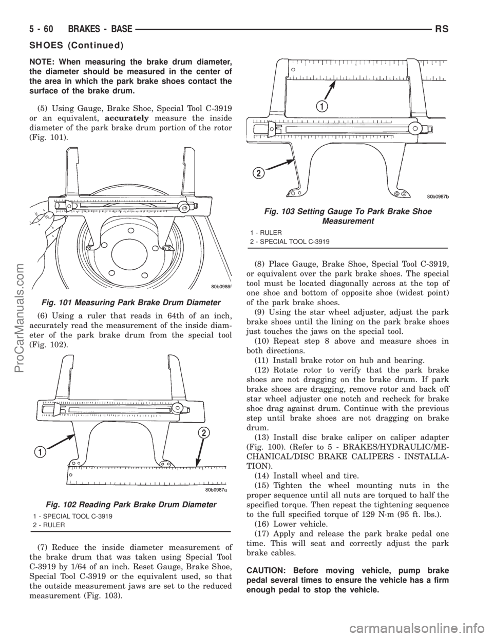
(5) Using Gauge, Brake Shoe, Special Tool C-3919
or an equivalent,accuratelymeasure the inside
diameter of the park brake drum portion of the rotor
(Fig. 101).
(6) Using a ruler that reads in 64th of an inch,
accurately read the measurement of the inside diam-
eter of the park brake drum from the special tool
(Fig. 102).
(7) Reduce the inside diameter measurement of
the brake drum that was taken using Special Tool
C-3919 by 1/64 of an inch. Reset Gauge, Brake Shoe,
Special Tool C-3919 or the equivalent used, so that
the outside measurement jaws are set to the reduced
measurement (Fig. 103).(8) Place Gauge, Brake Shoe, Special Tool C-3919,
or equivalent over the park brake shoes. The special
tool must be located diagonally across at the top of
one shoe and bottom of opposite shoe (widest point)
of the park brake shoes.
(9) Using the star wheel adjuster, adjust the park
brake shoes until the lining on the park brake shoes
just touches the jaws on the special tool.
(10) Repeat step 8 above and measure shoes in
both directions.
(11) Install brake rotor on hub and bearing.
(12) Rotate rotor to verify that the park brake
shoes are not dragging on the brake drum. If park
brake shoes are dragging, remove rotor and back off
star wheel adjuster one notch and recheck for brake
shoe drag against drum. Continue with the previous
step until brake shoes are not dragging on brake
drum.
(13) Install disc brake caliper on caliper adapter
(Fig. 100). (Refer to 5 - BRAKES/HYDRAULIC/ME-
CHANICAL/DISC BRAKE CALIPERS - INSTALLA-
TION).
(14) Install wheel and tire.
(15) Tighten the wheel mounting nuts in the
proper sequence until all nuts are torqued to half the
specified torque. Then repeat the tightening sequence
to the full specified torque of 129 N´m (95 ft. lbs.).
(16) Lower vehicle.
(17) Apply and release the park brake pedal one
time. This will seat and correctly adjust the park
brake cables.
CAUTION: Before moving vehicle, pump brake
pedal several times to ensure the vehicle has a firm
enough pedal to stop the vehicle.
Fig. 101 Measuring Park Brake Drum Diameter
Fig. 102 Reading Park Brake Drum Diameter
1 - SPECIAL TOOL C-3919
2 - RULER
Fig. 103 Setting Gauge To Park Brake Shoe
Measurement
1 - RULER
2 - SPECIAL TOOL C-3919
5 - 60 BRAKES - BASERS
SHOES (Continued)
ProCarManuals.com
Page 229 of 2321
CAUTION: If welding work is to be performed on the
vehicle, using an electric arc welder, the CAB con-
nector should be disconnected during the welding
operation.
CAUTION: Many components of the ABS System
are not serviceable and must be replaced as an
assembly. Do not disassemble any component
which is not designed to be serviced.
CAUTION: Only the recommended jacking or hoist-
ing positions for this vehicle are to be used when-
ever it is necessary to lift a vehicle. Failure to raise
a vehicle from the recommended locations could
result in lifting a vehicle by the hydraulic control
unit mounting bracket. Lifting a vehicle by the
hydraulic control unit mounting bracket will result
in damage to the mounting bracket and the hydrau-
lic control unit.
CAUTION: Brake fluid will damage painted surfaces.
If brake fluid is spilled on any painted surface,
wash off with water immediately.
STANDARD PROCEDURE - ANTILOCK BRAKE
SYSTEM BLEEDING
The base brake's hydraulic system must be bled
anytime air enters the hydraulic system. The ABS
though, particularly the ICU (HCU), should only be
bled when the HCU is replaced or removed from the
vehicle. The ABS must always be bled anytime it is
suspected that the HCU has ingested air. Under
most circumstances that require the bleeding of the
brakes hydraulic system, only the base brake
hydraulic system needs to be bled.
It is important to note that excessive air in the
brake system will cause a soft or spongy feeling
brake pedal.
During the brake bleeding procedure, be sure the
brake fluid level remains close to the FULL level in
the master cylinder fluid reservoir. Check the fluid
level periodically during the bleeding procedure and
add DOT 3 brake fluid as required.
The ABS must be bled as two independent braking
systems. The non-ABS portion of the brake systemwith ABS is to be bled the same as any non-ABS sys-
tem.
The ABS portion of the brake system must be bled
separately. Use the following procedure to properly
bleed the brake hydraulic system including the ABS.
BLEEDING
When bleeding the ABS system, the following
bleeding sequence must be followed to insure com-
plete and adequate bleeding.
(1) Make sure all hydraulic fluid lines are installed
and properly torqued.
(2) Connect the DRBIIItscan tool to the diagnos-
tics connector. The diagnostic connector is located
under the lower steering column cover to the left of
the steering column.
(3) Using the DRB, check to make sure the CAB
does not have any fault codes stored. If it does, clear
them using the DRB.
WARNING: WHEN BLEEDING THE BRAKE SYSTEM
WEAR SAFETY GLASSES. A CLEAR BLEED TUBE
MUST BE ATTACHED TO THE BLEEDER SCREWS
AND SUBMERGED IN A CLEAR CONTAINER FILLED
PART WAY WITH CLEAN BRAKE FLUID. DIRECT
THE FLOW OF BRAKE FLUID AWAY FROM YOUR-
SELF AND THE PAINTED SURFACES OF THE VEHI-
CLE. BRAKE FLUID AT HIGH PRESSURE MAY
COME OUT OF THE BLEEDER SCREWS WHEN
OPENED.
(4) Bleed the base brake system using the stan-
dard pressure or manual bleeding procedure. (Refer
to 5 - BRAKES - BASE - STANDARD PROCEDURE)
(5) Using the DRB, select ANTILOCK BRAKES,
followed by MISCELLANEOUS, then BLEED
BRAKES. Follow the instructions displayed. When
the scan tool displays TEST COMPLETED, discon-
nect the scan tool and proceed.
(6) Bleed the base brake system a second time.
Check brake fluid level in the reservoir periodically
to prevent emptying, causing air to enter the hydrau-
lic system.
(7) Fill the master cylinder reservoir to the full
level.
(8) Test drive the vehicle to be sure the brakes are
operating correctly and that the brake pedal does not
feel spongy.
5 - 70 BRAKES - ABSRS
BRAKES - ABS (Continued)
ProCarManuals.com
Page 230 of 2321

SPECIFICATIONS
SPECIFICATIONS - ABS FASTENER TORQUE
(Refer to 5 - BRAKES - BASE - SPECIFICA-
TIONS)
TONE WHEEL RUNOUT
DESCRIPTION SPECIFICATION
Front Tone Wheel
Maximum Runout0.15 mm (0.006 in.)
Rear Tone Wheel
Maximum Runout0.15 mm (0.006 in.)
WHEEL SPEED SENSOR AIR GAP
DESCRIPTION SPECIFICATION
Front Sensor0.35 ± 1.20 mm
0.014 ± 0.047 in.
Rear Sensor0.40 ± 1.20 mm
0.016 ± 0.047 in.
FRONT WHEEL SPEED
SENSOR
REMOVAL - WHEEL SPEED SENSOR (FRONT)
(1) Raise vehicle. (Refer to LUBRICATION &
MAINTENANCE/HOISTING - STANDARD PROCE-
DURE)
(2) Remove the tire and wheel assembly.
(3) Remove the sensor cable routing clamp screws.
CAUTION: When disconnecting the wheel speed
sensor from vehicle wiring harness, be careful not
to damage pins on connector
(4) Remove speed sensor cable grommets from
intermediate bracket on strut.
(5) Disconnect speed sensor cable from vehicle wir-
ing harness behind fender well shield.
(6) Remove the wheel speed sensor head mounting
bolt (Fig. 1).
(7) Remove sensor head from steering knuckle. If
sensor has seized due to corrosion,DO NOT USE
PLIERS ON SENSOR HEAD.Use a hammer and a
punch and tap edge of sensor ear, rocking the sensor
side-to-side until free.
(8) Remove front wheel speed sensor from vehicle.
INSTALLATION - WHEEL SPEED SENSOR
(FRONT)
CAUTION: Proper installation of wheel speed sen-
sor cables is critical to continued system operation.
Be sure that cables are installed in retainers. Fail-
ure to install cables in retainers as shown in this
section may result in contact with moving parts and
over extension of cables, resulting in an open cir-
cuit.
(1) Connect the front wheel speed sensor cable to
the vehicle wiring harness connector. Be sure speed
sensor cable connector is fully seated and locked into
vehicle wiring harness connector.
(2) Install the bolts attaching the routing clamps
to the body of the vehicle. Tighten the bolts to a
torque of 11 N´m (95 in. lbs.).
(3) Insert speed sensor cable grommets into inter-
mediate bracket on strut.
(4) Install the wheel speed sensor head mounting
bolt (Fig. 1). Tighten the bolt to a torque of 12 N´m
(105 in. lbs.)
(5) Install the wheel and tire assembly on vehicle.
(6) Lower vehicle.
(7) Road test vehicle to ensure proper operation of
the base and ABS brake systems.
Fig. 1 Front Wheel Speed Sensor Attaching Bolt
1 - MOUNTING BOLT
2 - WHEEL SPEED SENSOR
3 - DRIVESHAFT
4 - TONE WHEEL
5 - STEERING KNUCKLE
RSBRAKES - ABS5-71
BRAKES - ABS (Continued)
ProCarManuals.com
Page 231 of 2321

REAR WHEEL SPEED SENSOR
-AWD
REMOVAL - WHEEL SPEED SENSOR
(REAR-AWD)
(1) Raise vehicle. (Refer to LUBRICATION &
MAINTENANCE/HOISTING - STANDARD PROCE-
DURE)
CAUTION: When disconnecting speed sensor cable
from vehicle wiring harness be careful not to dam-
age pins on the electrical connectors. Also, inspect
connectors for any signs of previous damage.
(2) Remove grommet from floor pan of vehicle and
disconnect speed sensor cable connector from vehicle
wiring harness (Fig. 2).
CAUTION: When removing rear wheel speed sensor
cable from routing clips, be sure not to damage the
routing clips. Routing clips that are molded onto
the brake hose will require replacement of the brake
hose if damaged during removal or installation of
the speed sensor cable.
(3) Carefully remove speed sensor cable from
press-in routing clips along brake hose and tubing.
(4) Remove bolt securing wheel speed sensor cable
metal clip to rear of axle. Remove metal clip from
cable if necessary.
CAUTION: If speed sensor head has seized due to
corrosion, do not use pliers on speed sensor head
in an attempt to remove it. Use a hammer and apunch and tap mounting flange edge side-to-side,
rocking the sensor until free.
(5) Remove wheel speed sensor head attaching
bolt.
(6) Remove wheel speed sensor head from the axle,
and remove sensor from vehicle.
INSTALLATION - WHEEL SPEED SENSOR
(REAR-AWD)
CAUTION: Proper installation of wheel speed sen-
sor cables is critical to continued system operation.
Be sure that cables are installed in retainers. Fail-
ure to install cables in retainers as indicated may
result in contact with moving parts or over-exten-
sion of cables, resulting in an open circuit.
(1) Install wheel speed sensor head in axle flange.
CAUTION: Prior to installing the speed sensor head
attaching bolt, the plastic anti-rotation pin must be
fully seated into the bearing flange.
(2) Install wheel speed sensor head attaching bolt.
Tighten bolt to a torque 12 N´m (105 in. lbs.).
(3) Check the air gap between the face of the
wheel speed sensor and the top surface of the tone
wheel. (Refer to 5 - BRAKES - SPECIFICATIONS)
CAUTION: When installing wheel speed sensor
cable in the routing clips on rear brake flex hose,
be sure not to damage the routing clips. Routing
clips are molded onto the hose and will require
replacement of the brake hose if damaged.
(4) Install speed sensor cable under leaf spring
onto brake hose and tubing utilizing routing clips to
secure it in place.
(5) Install metal routing clip on speed sensor cable
and mount it to rear of axle with mounting bolt.
Tighten mounting bolt to 16 N´m (140 in. lbs.).
(6) Connect wheel speed sensor cable to vehicle
wiring harness (Fig. 2).Be sure speed sensor cable
connector is fully seated and locked into vehi-
cle wiring harness connector.
(7) Install speed sensor cable grommet into the
floor pan, being sure the grommet is fully seated into
the access hole.
(8) Lower vehicle.
(9) Road test vehicle to ensure proper operation of
the base and ABS braking systems.
Fig. 2 WHEEL SPEED SENSOR CONNECTOR
1 - CONNECTOR
2 - FLOOR PAN
3 - GROMMET
5 - 72 BRAKES - ABSRS
ProCarManuals.com
Page 236 of 2321
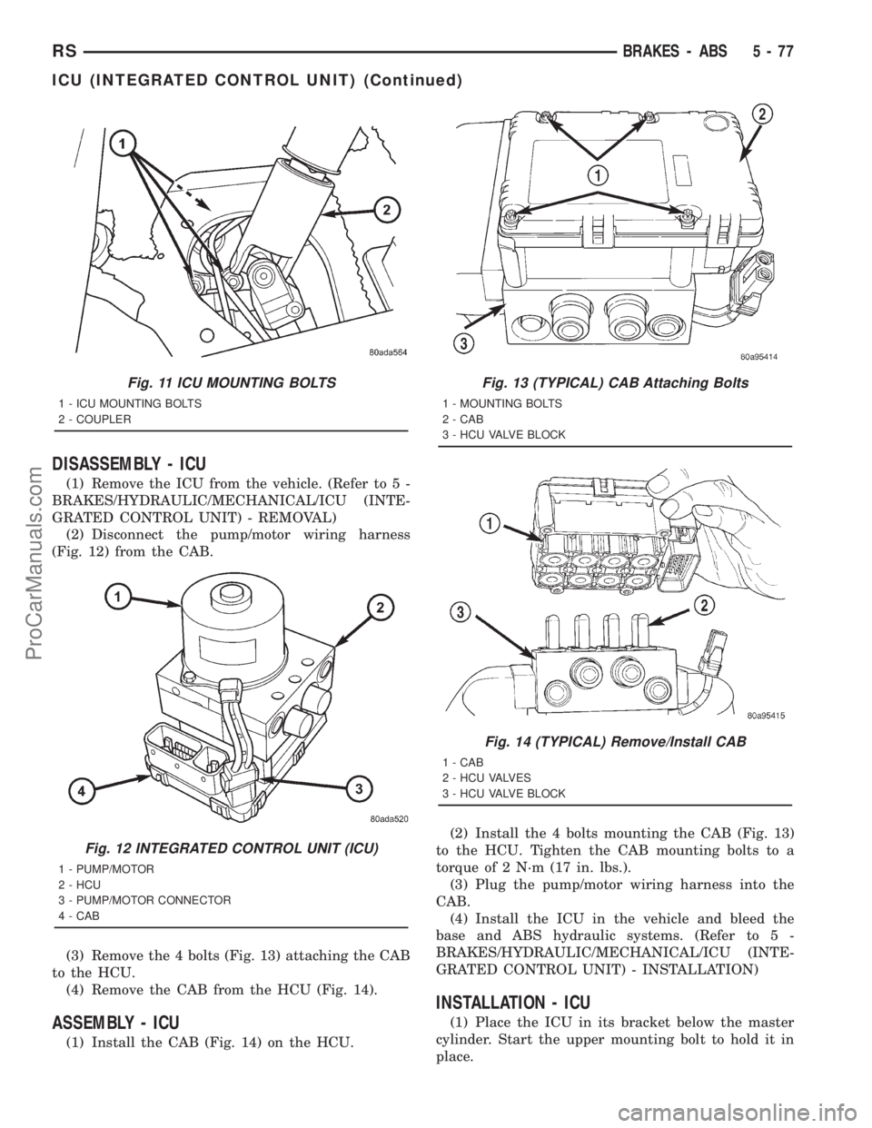
DISASSEMBLY - ICU
(1) Remove the ICU from the vehicle. (Refer to 5 -
BRAKES/HYDRAULIC/MECHANICAL/ICU (INTE-
GRATED CONTROL UNIT) - REMOVAL)
(2) Disconnect the pump/motor wiring harness
(Fig. 12) from the CAB.
(3) Remove the 4 bolts (Fig. 13) attaching the CAB
to the HCU.
(4) Remove the CAB from the HCU (Fig. 14).
ASSEMBLY - ICU
(1) Install the CAB (Fig. 14) on the HCU.(2) Install the 4 bolts mounting the CAB (Fig. 13)
to the HCU. Tighten the CAB mounting bolts to a
torque of 2 N´m (17 in. lbs.).
(3) Plug the pump/motor wiring harness into the
CAB.
(4) Install the ICU in the vehicle and bleed the
base and ABS hydraulic systems. (Refer to 5 -
BRAKES/HYDRAULIC/MECHANICAL/ICU (INTE-
GRATED CONTROL UNIT) - INSTALLATION)
INSTALLATION - ICU
(1) Place the ICU in its bracket below the master
cylinder. Start the upper mounting bolt to hold it in
place.
Fig. 11 ICU MOUNTING BOLTS
1 - ICU MOUNTING BOLTS
2 - COUPLER
Fig. 12 INTEGRATED CONTROL UNIT (ICU)
1 - PUMP/MOTOR
2 - HCU
3 - PUMP/MOTOR CONNECTOR
4 - CAB
Fig. 13 (TYPICAL) CAB Attaching Bolts
1 - MOUNTING BOLTS
2 - CAB
3 - HCU VALVE BLOCK
Fig. 14 (TYPICAL) Remove/Install CAB
1 - CAB
2 - HCU VALVES
3 - HCU VALVE BLOCK
RSBRAKES - ABS5-77
ICU (INTEGRATED CONTROL UNIT) (Continued)
ProCarManuals.com