2001 DODGE TOWN AND COUNTRY torque
[x] Cancel search: torquePage 382 of 2321

²Output Shaft Speed Sensor
Some examples ofindirect inputsto the TCM
are:
²Engine/Body Identification
²Manifold Pressure
²Target Idle
²Torque Reduction Confirmation
²Speed Control ON/OFF Switch
²Engine Coolant Temperature
²Ambient/Battery Temperature
²Brake Switch Status
²DRB Communication
Based on the information received from these var-
ious inputs, the TCM determines the appropriate
shift schedule and shift points, depending on the
present operating conditions and driver demand.
This is possible through the control of various direct
and indirect outputs.
Some examples of TCMdirect outputsare:
²Transmission Control Relay
²Solenoids (LR/CC, 2/4, OD and UD)
²Vehicle Speed (to PCM)
²Torque Reduction Request (to PCM)
An example of a TCMindirect outputis:
²Transmission Temperature (to PCM)
In addition to monitoring inputs and controlling
outputs, the TCM has other important responsibili-
ties and functions:
²Storing and maintaining Clutch Volume Indices
(CVI)
²Storing and selecting appropriate Shift Sched-
ules
²System self-diagnostics²Diagnostic capabilities (with DRB scan tool)
CLUTCH VOLUME INDEX (CVI)
An important function of the TCM is to monitor
Clutch Volume Index (CVI). CVIs represent the vol-
ume of fluid needed to compress a clutch pack.
The TCM monitors gear ratio changes by monitor-
ing the Input and Output Speed Sensors. The Input,
or Turbine Speed Sensor sends an electrical signal to
the TCM that represents input shaft rpm. The Out-
put Speed Sensor provides the TCM with output
shaft speed information.
By comparing the two inputs, the TCM can deter-
mine transaxle gear ratio. This is important to the
CVI calculation because the TCM determines CVIs
by monitoring how long it takes for a gear change to
occur (Fig. 14).
Gear ratios can be determined by using the DRB
Scan Tool and reading the Input/Output Speed Sen-
sor values in the ªMonitorsº display. Gear ratio can
be obtained by dividing the Input Speed Sensor value
by the Output Speed Sensor value.
For example, if the input shaft is rotating at 1000
rpm and the output shaft is rotating at 500 rpm,
then the TCM can determine that the gear ratio is
Fig. 13 Transmission Control Module (TCM)
Location
1 - TRANSMISSION CONTROL MODULE (TCM)
Fig. 14 Example of CVI Calculation
1 - OUTPUT SPEED SENSOR
2 - OUTPUT SHAFT
3 - CLUTCH PACK
4 - SEPARATOR PLATE
5 - FRICTION DISCS
6 - INPUT SHAFT
7 - INPUT SPEED SENSOR
8 - PISTON AND SEAL
RSELECTRONIC CONTROL MODULES8E-25
TRANSMISSION CONTROL MODULE (Continued)
ProCarManuals.com
Page 384 of 2321

Schedule Condition Expected Operation
HotOil temperature at start-up above
80É F± Normal operation (upshift,
kickdowns, and coastdowns)
± Full EMCC, no PEMCC except to
engage FEMCC (except at closed
throttle at speeds above 70-83 mph)
OverheatOil temperature above 240É F or
engine coolant temperature above
244É F± Delayed 2-3 upshift (25-32 mph)
± Delayed 3-4 upshift (41-48 mph)
± 3rd gear FEMCC from 30-48 mph
± 3rd gear PEMCC from 27-31 mph
Super OverheatOil temperature above 260É F ± All9Overheat9shift schedule
features apply
± 2nd gear PEMCC above 22 mph
± Above 22 mph the torque
converter will not unlock unless the
throttle is closed or if a wide open
throttle 2nd PEMCC to 1 kickdown
is made
STANDARD PROCEDURE - PINION FACTOR
SETTING
NOTE: This procedure must be performed if the
Transmission Control Module (TCM) has been
replaced with a NEW or replacement unit. Failure to
perform this procedure will result in an inoperative
or improperly calibrated speedometer.
The vehicle speed readings for the speedometer are
taken from the output speed sensor. The TCM must
be calibrated to the different combinations of equip-
ment (final drive and tires) available. Pinion Factor
allows the technician to set the Transmission Control
Module initial setting so that the speedometer read-
ings will be correct. To properly read and/or reset the
Pinion Factor, it is necessary to use a DRB scan tool.
(1) Plug the DRB scan tool into the diagnostic con-
nector located under the instrument panel.
(2) Select the Transmission menu.
(3) Select the Miscellaneous menu.
(4) Select Pinion Factor. Then follow the instruc-
tions on the DRB scan tool screen.
STANDARD PROCEDURE - QUICK LEARN
PROCEDURE
The quick learn procedure requires the use of the
DRB scan tool. This program allows the electronic
transaxle system to recalibrate itself. This will pro-
vide the best possible transaxle operation.NOTE: The quick learn procedure should be per-
formed if any of the following procedures are per-
formed:
²Transaxle Assembly Replacement
²Transmission Control Module Replacement
²Solenoid/Pressure Switch Assembly Replacement
²Clutch Plate and/or Seal Replacement
²Valve Body Replacement or Recondition
To perform the Quick Learn Procedure, the follow-
ing conditions must be met:
²The brakes must be applied
²The engine speed must be above 500 rpm
²The throttle angle (TPS) must be less than 3
degrees
²The shift lever position must stay until
prompted to shift to overdrive
²The shift lever position must stay in overdrive
after the Shift to Overdrive prompt until the DRB
indicates the procedure is complete
²The calculated oil temperature must be above
60É and below 200É
(1) Plug the DRB scan tool into the diagnostic con-
nector. The connector is located under the instrument
panel.
(2) Go to the Transmission screen.
(3) Go to the Miscellaneous screen.
(4) Select Quick Learn Procedure. Follow the
instructions of the DRB to perform the Quick Learn
Procedure.
RSELECTRONIC CONTROL MODULES8E-27
TRANSMISSION CONTROL MODULE (Continued)
ProCarManuals.com
Page 385 of 2321

STANDARD PROCEDURE - TCC BREAK-IN
VIEW/RESTART PROCEDURE
The Transmission Control Module (TCM) employs
a strategy which modifies torque converter clutch
(TCC) operation. This strategy conditions the torque
converter clutch disc for optimum converter clutch
engagement and feel throughout the life of the trans-
axle. The cycle inhibits FEMCC until six hours of
PEMCC operation have taken place, or the vehicle
has been driven 6,035 km (3750 miles). The cycle
automatically terminates when either the time or
mileage has been achieved, however, the mileage
may vary slightly from vehicle to vehicle.
The TCC break-in cycle must be restarted using
the DRB Scan Tool, and upon:
²Replacement of TCM on vehicle with less than
6,035 km (3750 miles) or less than 6 hours of
PEMCC operation
²Replacement of torque converter assembly at
any vehicle mileage
NOTE: Failure to restart the TCC Break-In Cycle
upon TCM replacement in vehicles with less than
six hours of PEMCC or less than 6,035 km (3750
miles), or upon torque converter replacement at any
mileage, may result in vehicle shudder during cer-
tain operating conditions.
Procedure
The DRB Scan Tool is required to view and/or
restart the TCC Break-In cycle.
(1) Connect the DRB Scan Tool to the vehicle diag-
nostic connector.
(2) Navigate to ªTCC Break-Inº via Transmission/
Transmission Control Module/Miscellaneous.
(3) View or Start TCC Break-In as prompted by
DRB menu.
REMOVAL
NOTE: If transmission control module is being
replaced with a new or replacement unit, the Pinion
Factor and Quick Learn procedures must be per-
formed. (Refer to 8 - ELECTRICAL/ELECTRONIC
CONTROL MODULES/TRANSMISSION CONTROL
MODULE - STANDARD PROCEDURE) (Refer to 8 -
ELECTRICAL/ELECTRONIC CONTROL MODULES/
TRANSMISSION CONTROL MODULE - STANDARD
PROCEDURE) If vehicle has less than 6,035 km
(3750 miles), the Torque Converter Clutch (TCC)
Break-In Strategy reset procedure must also be per-
formed. (Refer to 8 - ELECTRICAL/ELECTRONIC
CONTROL MODULES/TRANSMISSION CONTROL
MODULE - STANDARD PROCEDURE)(1) Disconnect battery negative cable.
(2) Raise vehicle on hoist.
(3) Remove left front tire/wheel assembly.
(4) Pull back splash shield to gain access to TCM
location.
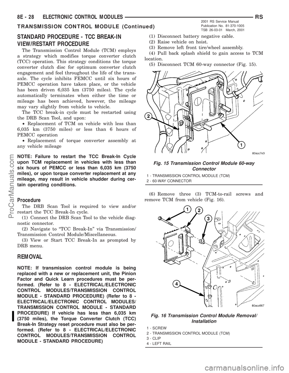
(5) Disconnect TCM 60-way connector (Fig. 15).
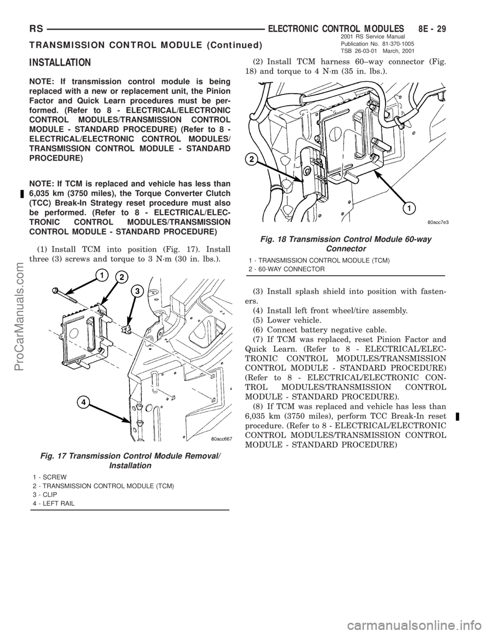
(6) Remove three (3) TCM-to-rail screws and
remove TCM from vehicle (Fig. 16).
Fig. 15 Transmission Control Module 60-way
Connector
1 - TRANSMISSION CONTROL MODULE (TCM)
2 - 60-WAY CONNECTOR
Fig. 16 Transmission Control Module Removal/
Installation
1 - SCREW
2 - TRANSMISSION CONTROL MODULE (TCM)
3 - CLIP
4 - LEFT RAIL
8E - 28 ELECTRONIC CONTROL MODULESRS
TRANSMISSION CONTROL MODULE (Continued)
2001 RS Service Manual
Publication No. 81-370-1005
TSB 26-03-01 March, 2001
ProCarManuals.com
Page 386 of 2321

INSTALLATION
NOTE: If transmission control module is being
replaced with a new or replacement unit, the Pinion
Factor and Quick Learn procedures must be per-
formed. (Refer to 8 - ELECTRICAL/ELECTRONIC
CONTROL MODULES/TRANSMISSION CONTROL
MODULE - STANDARD PROCEDURE) (Refer to 8 -
ELECTRICAL/ELECTRONIC CONTROL MODULES/
TRANSMISSION CONTROL MODULE - STANDARD
PROCEDURE)
NOTE: If TCM is replaced and vehicle has less than
6,035 km (3750 miles), the Torque Converter Clutch
(TCC) Break-In Strategy reset procedure must also
be performed. (Refer to 8 - ELECTRICAL/ELEC-
TRONIC CONTROL MODULES/TRANSMISSION
CONTROL MODULE - STANDARD PROCEDURE)
(1) Install TCM into position (Fig. 17). Install
three (3) screws and torque to 3 N´m (30 in. lbs.).(2) Install TCM harness 60±way connector (Fig.
18) and torque to 4 N´m (35 in. lbs.).
(3) Install splash shield into position with fasten-
ers.
(4) Install left front wheel/tire assembly.
(5) Lower vehicle.
(6) Connect battery negative cable.
(7) If TCM was replaced, reset Pinion Factor and
Quick Learn. (Refer to 8 - ELECTRICAL/ELEC-
TRONIC CONTROL MODULES/TRANSMISSION
CONTROL MODULE - STANDARD PROCEDURE)
(Refer to 8 - ELECTRICAL/ELECTRONIC CON-
TROL MODULES/TRANSMISSION CONTROL
MODULE - STANDARD PROCEDURE).
(8) If TCM was replaced and vehicle has less than
6,035 km (3750 miles), perform TCC Break-In reset
procedure. (Refer to 8 - ELECTRICAL/ELECTRONIC
CONTROL MODULES/TRANSMISSION CONTROL
MODULE - STANDARD PROCEDURE)
Fig. 17 Transmission Control Module Removal/
Installation
1 - SCREW
2 - TRANSMISSION CONTROL MODULE (TCM)
3 - CLIP
4 - LEFT RAIL
Fig. 18 Transmission Control Module 60-way
Connector
1 - TRANSMISSION CONTROL MODULE (TCM)
2 - 60-WAY CONNECTOR
RSELECTRONIC CONTROL MODULES8E-29
TRANSMISSION CONTROL MODULE (Continued)
2001 RS Service Manual
Publication No. 81-370-1005
TSB 26-03-01 March, 2001
ProCarManuals.com
Page 403 of 2321

REMOVAL - BATTERY
WARNING: A SUITABLE PAIR OF HEAVY DUTY
RUBBER GLOVES SHOULD BE WORN WHEN
REMOVING OR SERVICING A BATTERY.
WARNING: SAFETY GLASSES SHOULD BE WORN
WHEN REMOVING OR SERVICING A BATTERY.
WARNING: REMOVE METALLIC JEWELRY TO
AVOID INJURY BY ACCIDENTAL ARCING OF BAT-
TERY CURRENT.
(1) Verify that the ignition switch and all accesso-
ries are OFF.
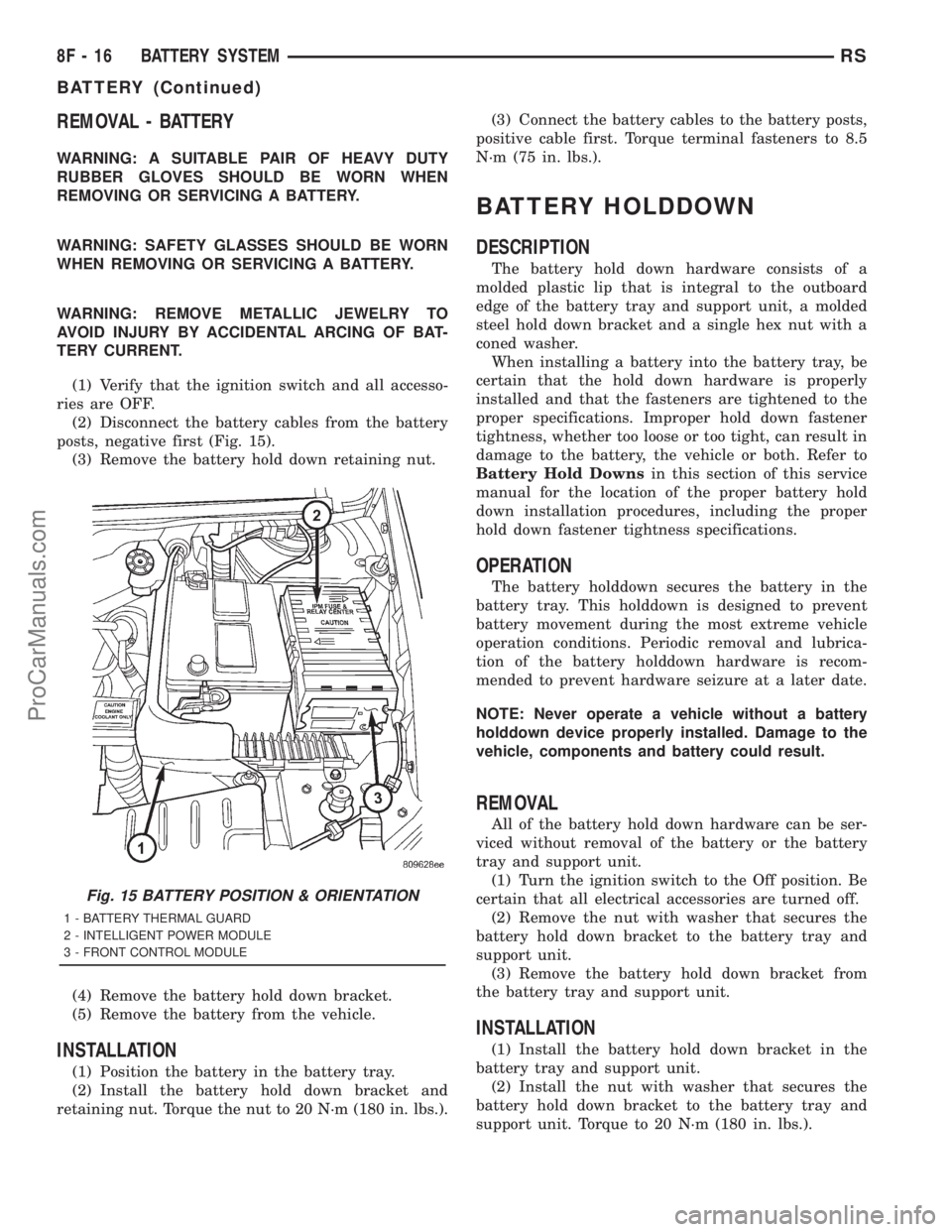
(2) Disconnect the battery cables from the battery
posts, negative first (Fig. 15).
(3) Remove the battery hold down retaining nut.
(4) Remove the battery hold down bracket.
(5) Remove the battery from the vehicle.
INSTALLATION
(1) Position the battery in the battery tray.
(2) Install the battery hold down bracket and
retaining nut. Torque the nut to 20 N´m (180 in. lbs.).(3) Connect the battery cables to the battery posts,
positive cable first. Torque terminal fasteners to 8.5
N´m (75 in. lbs.).
BATTERY HOLDDOWN
DESCRIPTION
The battery hold down hardware consists of a
molded plastic lip that is integral to the outboard
edge of the battery tray and support unit, a molded
steel hold down bracket and a single hex nut with a
coned washer.
When installing a battery into the battery tray, be
certain that the hold down hardware is properly
installed and that the fasteners are tightened to the
proper specifications. Improper hold down fastener
tightness, whether too loose or too tight, can result in
damage to the battery, the vehicle or both. Refer to
Battery Hold Downsin this section of this service
manual for the location of the proper battery hold
down installation procedures, including the proper
hold down fastener tightness specifications.
OPERATION
The battery holddown secures the battery in the
battery tray. This holddown is designed to prevent
battery movement during the most extreme vehicle
operation conditions. Periodic removal and lubrica-
tion of the battery holddown hardware is recom-
mended to prevent hardware seizure at a later date.
NOTE: Never operate a vehicle without a battery
holddown device properly installed. Damage to the
vehicle, components and battery could result.
REMOVAL
All of the battery hold down hardware can be ser-
viced without removal of the battery or the battery
tray and support unit.
(1) Turn the ignition switch to the Off position. Be
certain that all electrical accessories are turned off.
(2) Remove the nut with washer that secures the
battery hold down bracket to the battery tray and
support unit.
(3) Remove the battery hold down bracket from
the battery tray and support unit.
INSTALLATION
(1) Install the battery hold down bracket in the
battery tray and support unit.
(2) Install the nut with washer that secures the
battery hold down bracket to the battery tray and
support unit. Torque to 20 N´m (180 in. lbs.).
Fig. 15 BATTERY POSITION & ORIENTATION
1 - BATTERY THERMAL GUARD
2 - INTELLIGENT POWER MODULE
3 - FRONT CONTROL MODULE
8F - 16 BATTERY SYSTEMRS
BATTERY (Continued)
ProCarManuals.com
Page 409 of 2321

DIAGNOSIS AND TESTING - ON-BOARD
DIAGNOSTIC SYSTEM
The Powertrain Control Module (PCM) monitors
critical input and output circuits of the charging sys-
tem, making sure they are operational. A Diagnostic
Trouble Code (DTC) is assigned to each input and
output circuit monitored by the OBD system. Some
circuits are checked continuously and some are
checked only under certain conditions.
If the OBD system senses that a monitored circuit
is bad, it will put a DTC into electronic memory. The
DTC will stay in electronic memory as long as the
circuit continues to be bad. The PCM is programmed
to clear the memory after 50 engine starts if the
problem does not occur again.
DIAGNOSTIC TROUBLE CODES
A DTC description can be read using the DRBt
scan tool. Refer to the appropriate Powertrain Diag-
nostic Procedures manual for information.
A DTC does not identify which component in a cir-
cuit is bad. Thus, a DTC should be treated as a
symptom, not as the cause for the problem. In some
cases, because of the design of the diagnostic test
procedure, a DTC can be the reason for another DTC
to be set. Therefore, it is important that the test pro-cedures be followed in sequence, to understand what
caused a DTC to be set.
ERASING DIAGNOSTIC TROUBLE CODES
The DRBIIItScan Tool must be used to erase a
DTC.
SPECIFICATIONS
GENERATOR
Type Engine Minimun Test
Amperage
Denso 2.4 L 135 Amp
Denso 3.3/3.8L 135 Amp or 160
Amp
Test Specification:
1. Engine RPM : 2500 RPM620 RPM
2. Voltage Output : 14.0 V60.5 V
3. Field Current : 5 amps60.1 amps
Part number is located on the side of the generator.
TORQUE
DESCRIPTION N´m Ft. Lbs. In. Lbs.
Battery Hold Down Clamp
Bolt20 14.7 180
Generator B+ Nut 12.4 9.2 110
Battery Terminal Nut 4 35
Generator Mounting Bolt
2.4L28.2 20.8 250
Starter Solenoid Battery
Nut 3.3/3.8L54.2 40
Generator Decoupler 109.8 81
8F - 22 CHARGINGRS
CHARGING (Continued)
ProCarManuals.com
Page 413 of 2321

INSTALLATION
(1) Install the Generator Decoupler to the genera-
tor shaft.
(2) Use Special Tool #8433 (Fig. 6) to tighten the
Generator Decoupler. Refer to the torque chart for
the proper torque.
(3) Install the Air Box, refer to the Engine section
for more information.
(4) Raise vehicle and support.
(5) Install accessory drive belt, refer to the Cooling
System section for proper procedures (Fig. 5).
(6) Install the right front lower splash shield.
(7) Lower vehicle.
(8) Connect battery negative cable.
VOLTAGE REGULATOR
DESCRIPTION
The Electronic Voltage Regulator (EVR) is not a
separate component. It is actually a voltage regulat-
ing circuit located within the Powertrain Control
Module (PCM). The EVR is not serviced separately. If
replacement is necessary, the PCM must be replaced.
OPERATION
The amount of DC current produced by the gener-
ator is controlled by EVR circuitry contained within
the PCM. This circuitry is connected in series with
the generators second rotor field terminal and its
ground.
Voltage is regulated by cycling the ground path to
control the strength of the rotor magnetic field. The
EVR circuitry monitors system line voltage (B+) and
battery temperature or inlet air temperature sensor
(refer to Battery Temperature Sensor or Inlet Air
Temperature Sensor for more information). It then
determines a target charging voltage. If sensed bat-
tery voltage is 325 mv or lower than the target volt-
age, the PCM grounds the field winding until sensed
battery volage is 325 mv above target voltage. A cir-
cuit in the PCM cycles the ground side of the gener-
ator field up to 250 times per second (250Hz), but
has the capability to ground the field control wire
100% of the time (full field) to achieve the target
voltage. If the charging rate cannot be monitored
(limp-in), a duty cycle of 25% is used by the PCM in
order to have some generator output. Also refer to
Charging System Operation for additional informa-
tion.
REMOVAL
The electronic voltage regulator is not a serviced
separately. If replacement is necessary, the PCM
must be replaced.
Fig. 6 SPECIAL TOOL 8433 AND DECOUPLER
8F - 26 CHARGINGRS
GENERATOR DECOUPLER PULLEY (Continued)
ProCarManuals.com
Page 416 of 2321

CONDITION POSSIBLE CAUSE CORRECTION
3. STARTER ASSEMBLY
FAULTY.3. IF ALL OTHER STARTING SYSTEM COMPONENTS AND
CIRCUITS CHECK OK, REPLACE STARTER ASSEMBLY.
4. ENGINE SEIZED. 4. REFER TO THE ENGINE SECTION, FOR DIAGNOSTIC AND
SERVICE PROCEDURES.
5. LOOSE
CONNECTION AT
BATTERY, PDC,
STARTER, OR ENGINE
GROUND.5. INSPECT FOR LOOSE CONNECTIONS.
6. FAULTY TEETH ON
RING GEAR.6. ROTATE FLYWHEEL 360É, AND INSPECT TEETHAND RING
GEAR REPLACED IF DAMAGED.
STARTER
ENGAGES,
SPINS OUT
BEFORE
ENGINE
STARTS.1. BROKEN TEETH ON
STARTER RING GEAR.1. REMOVE STARTER. INSPECT RING GEAR AND REPLACE
IF NECESSARY.
2. STARTER ASSEMBLY
FAULTY.2. IF ALL OTHER STARTING SYSTEM COMPONENTS AND
CIRCUITS CHECK OK, REPLACE STARTER ASSEMBLY.
STARTER DOES
NOT
DISENGAGE.1. STARTER
IMPROPERLY
INSTALLED.1. INSTALL STARTER. TIGHTEN STARTER MOUNTING
HARDWARE TO CORRECT TORQUE SPECIFICATIONS.
2. STARTER RELAY
FAULTY.2. REFER TO RELAY TEST, IN THIS SECTION. REPLACE
RELAY, IF NECESSARY.
3. IGNITION SWITCH
FAULTY.3. REFER TO IGNITION SWITCH TEST, IN THE STEERING
SECTION.. REPLACE SWITCH, IF NECESSARY.
4. STARTER ASSEMBLY
FAULTY.4. IF ALL OTHER STARTING SYSTEM COMPONENTS AND
CIRCUITS CHECK OK, REPLACE STARTER ASSEMBLY.
5. FAULTY TEETH ON
RING GEAR.5. ROTATE FLYWHEEL 360É, AND INSPECT TEETH AND RING
GEAR REPLACED IF DAMAGED.
CONTROL CIRCUIT TEST
The starter control circuit has:
²Starter motor with integral solenoid
²Starter relay
²Transmission range sensor, or Park/Neutral
Position switch with automatic transmissions
²Ignition switch
²Battery
²All related wiring and connections
²Powertrain Control Module (PCM)
CAUTION: Before performing any starter tests, the
ignition and fuel systems must be disabled.
²To disable ignition and fuel systems, disconnect
the Automatic Shutdown Relay (ASD). The ASD relay
is located in the Power Distribution Center (PDC).
Refer to the PDC cover for the proper relay location.
STARTER SOLENOID
WARNING: CHECK TO ENSURE THAT THE TRANS-
MISSION IS IN THE PARK POSITION WITH THE
PARKING BRAKE APPLIED.
(1) Verify battery condition. Battery must be in
good condition with a full charge before performing
any starter tests. Refer to Battery Tests.
(2) Perform Starter Solenoid test BEFORE per-
forming the starter relay test.
(3) Perform a visual inspection of the starter/
starter solenoid for corrosion, loose connections or
faulty wiring.
(4) Locate and remove the starter relay from the
Power Distribution Center (PDC). Refer to the PDC
label for relay identification and location.
RSSTARTING8F-29
STARTING (Continued)
ProCarManuals.com