2001 DODGE TOWN AND COUNTRY door lock
[x] Cancel search: door lockPage 1915 of 2321
Before removing the glass, check the availability of
replacement components.
SEATS
Seat modules are made up of a seat frame, seat
cushion, seat back cushion, a covering material, and
the electrical components used for power operation, if
equipped. Some seat systems also contain seat belt
components and supplemental restraint systems.
Seat assemblies transport the occupants in comfort
and safety. Seat assemblies also help position occu-
pants correctly in the event of airbag deployment.
Seat cushions, coverings, and electrical components
are serviceable. Refer to the appropriate group in
this manual.
EXTERIOR COMPONENTS
Exterior sheet metal components make up the
exterior of the vehicle. Some exterior metal systems
are welded assemblies, such as doors and hoods.
Some exterior trim items are made of composite.
The exterior is finished in various metal stampings
and composite moldings. These assemblies give the
vehicle a finished appearance and protect the occu-
pants from the elements. Some components are part
of the energy absorbing system used to protect the
occupants in collisions. The exterior sheet metal is
repairable and adjustable for fit and finish. Welded
and bonded component systems are adjustable as a
system. Trim components made of composite are
stamped with the type of material used.
DaimlerChrysler uses various fasteners to retain
trim items. At times, it is not possible to remove trim
items without damaging the fastener. If it is not pos-
sible to remove an item without damaging a compo-
nent, cut or break the fasteners and use new ones
when installing the component.
SAFETY PRECAUTIONS AND WARNINGS
WARNING:
EYE PROTECTION SHOULD BE USED WHEN SER-
VICING GLASS COMPONENTS. PERSONAL INJURY
CAN RESULT.
USE A OSHA APPROVED BREATHING FILTER
WHEN SPRAYING PAINT OR SOLVENTS IN A CON-
FINED AREA. PERSONAL INJURY CAN RESULT.
AVOID PROLONGED SKIN CONTACT WITH PETRO-
LEUM OR ALCOHOL BASED CLEANING SOLVENTS.
PERSONAL INJURY CAN RESULT.
DO NOT STAND UNDER A HOISTED VEHICLE THAT
IS NOT PROPERLY SUPPORTED ON SAFETY
STANDS. PERSONAL INJURY CAN RESULT.
CAUTION:
When holes must be drilled or punched in an innerbody panel, verify depth of space to the outer body
panel, electrical wiring, or other components. Dam-
age to vehicle can result.
Do not weld exterior panels unless combustible
material on the interior of vehicle is removed from
the repair area. Fire or hazardous conditions, can
result.
Always have a fire extinguisher ready for use when
welding.
Disconnect the negative battery cable clamp when
servicing electrical components that are live when
the ignition is OFF. Damage to electrical system can
result.
Do not use abrasive chemicals or compounds on
painted surfaces. Damage to finish can result.
Do not use harsh alkaline based cleaning solvents
on painted or upholstered surfaces. Damage to fin-
ish or color can result.
Do not hammer or pound on plastic trim panel
when servicing interior trim. Plastic panels can
break.
DIAGNOSIS AND TESTING - WATER LEAKS
Water leaks can be caused by poor sealing,
improper body component alignment, body seam
porosity, missing plugs, or blocked drain holes. Cen-
trifugal and gravitational force can cause water to
drip from a location away from the actual leak point,
making leak detection difficult. All body sealing
points should be water tight in normal wet-driving
conditions. Water flowing downward from the front of
the vehicle should not enter the passenger or luggage
compartment. Moving sealing surfaces will not
always seal water tight under all conditions. At
times, side glass or door seals will allow water to
enter the passenger compartment during high pres-
sure washing or hard driving rain (severe) condi-
tions. Overcompensating on door or glass
adjustments to stop a water leak that occurs under
severe conditions can cause premature seal wear and
excessive closing or latching effort. After completing
a repair, water test vehicle to verify leak has stopped
before returning vehicle to use.
VISUAL INSPECTION BEFORE WATER LEAK TESTS
Verify that floor and body plugs are in place, body
drains are clear, and body components are properly
aligned and sealed. If component alignment or seal-
ing is necessary, refer to the appropriate section of
this group for proper procedures.
WATER LEAK TESTS
WARNING: DO NOT USE ELECTRIC SHOP LIGHTS
OR TOOLS IN WATER TEST AREA. PERSONAL
INJURY CAN RESULT.
23 - 2 BODYRS
BODY (Continued)
ProCarManuals.com
Page 1922 of 2321
(4) Allow the repaired area to cool and verify the
repair.
(5) Install trim panel.
SPECIFICATIONS
BODY LUBRICATION SPECIFICATIONS
LUBRICATION REQUIREMENTS
Body mechanisms and linkages should be
inspected, cleaned, and lubricated, as required, to
maintain ease of operation and to provide protectionagainst rust and wear. When performing other under
hood services, the hood latch release mechanism and
safety catch should be inspected, cleaned, and lubri-
cated. During the winter season, external door lock
cylinders should be lubricated to assure proper oper-
ation when exposed to water and ice.
Prior to the application of any lubricant, the parts
concerned should be wiped clean to remove dust and
grit. If necessary, a suitable solvent can be used to
clean the item to be lubricated. After lubricating a
component, any excess oil or grease should be
removed.
LUBRICANT APPLICATION
DOOR LOCK CYLINDERS
(1) Apply a small amount of lubricant directly into
the lock cylinder.
(2) Apply a small amount of lubricant to the key.
(3) Insert key into lock cylinder and cycle the
mechanism from the locked to the unlocked position.
NOTE: Do not add more lubricant.
(4) Cycle the lock cylinder mechanism several
times to allow the lubricant to flow throughout the
cylinder.
(5) Wipe all lubricant from exterior of lock cylinder
and key.
ALL OTHER BODY MECHANISMS
(1) Clean component as described above.
(2) Apply specified lubricant to all pivoting and
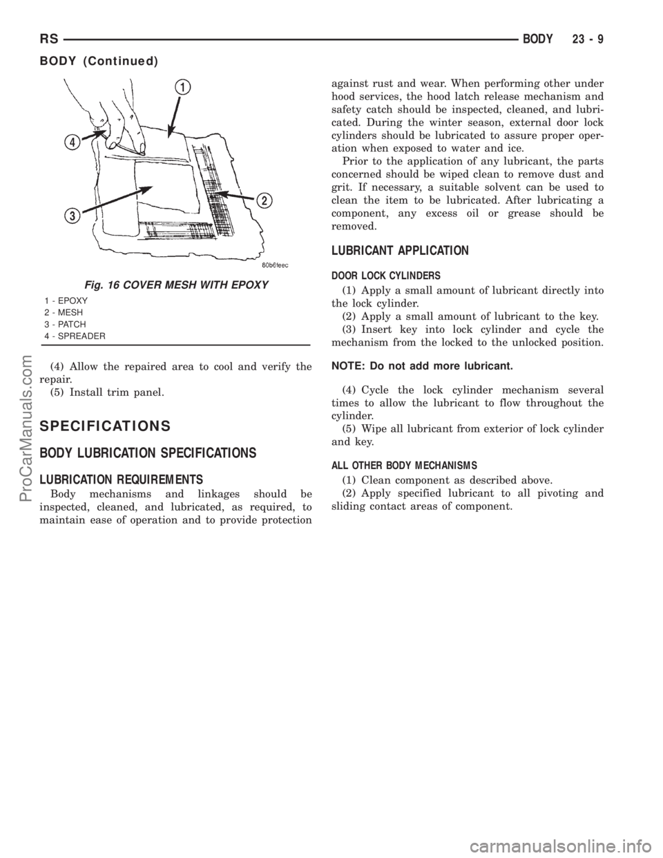
sliding contact areas of component.Fig. 16 COVER MESH WITH EPOXY
1 - EPOXY
2 - MESH
3 - PATCH
4 - SPREADER
RSBODY23-9
BODY (Continued)
ProCarManuals.com
Page 1923 of 2321
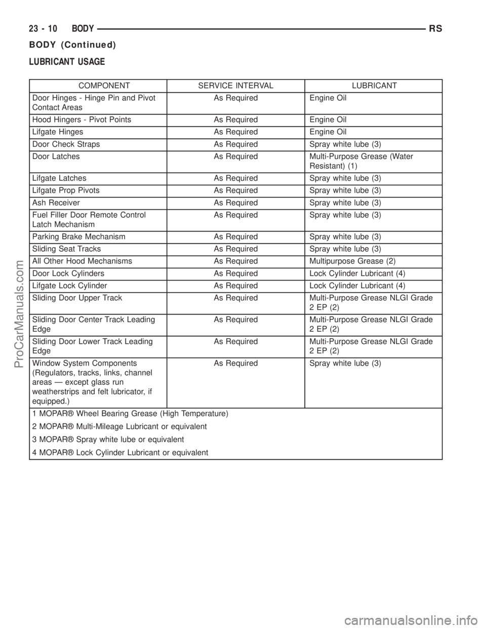
LUBRICANT USAGE
COMPONENT SERVICE INTERVAL LUBRICANT
Door Hinges - Hinge Pin and Pivot
Contact AreasAs Required Engine Oil
Hood Hingers - Pivot Points As Required Engine Oil
Lifgate Hinges As Required Engine Oil
Door Check Straps As Required Spray white lube (3)
Door Latches As Required Multi-Purpose Grease (Water
Resistant) (1)
Lifgate Latches As Required Spray white lube (3)
Lifgate Prop Pivots As Required Spray white lube (3)
Ash Receiver As Required Spray white lube (3)
Fuel Filler Door Remote Control
Latch MechanismAs Required Spray white lube (3)
Parking Brake Mechanism As Required Spray white lube (3)
Sliding Seat Tracks As Required Spray white lube (3)
All Other Hood Mechanisms As Required Multipurpose Grease (2)
Door Lock Cylinders As Required Lock Cylinder Lubricant (4)
Lifgate Lock Cylinder As Required Lock Cylinder Lubricant (4)
Sliding Door Upper Track As Required Multi-Purpose Grease NLGI Grade
2 EP (2)
Sliding Door Center Track Leading
EdgeAs Required Multi-Purpose Grease NLGI Grade
2 EP (2)
Sliding Door Lower Track Leading
EdgeAs Required Multi-Purpose Grease NLGI Grade
2 EP (2)
Window System Components
(Regulators, tracks, links, channel
areas Ð except glass run
weatherstrips and felt lubricator, if
equipped.)As Required Spray white lube (3)
1 MOPARž Wheel Bearing Grease (High Temperature)
2 MOPARž Multi-Mileage Lubricant or equivalent
3 MOPARž Spray white lube or equivalent
4 MOPARž Lock Cylinder Lubricant or equivalent
23 - 10 BODYRS
BODY (Continued)
ProCarManuals.com
Page 2065 of 2321
DOOR - FRONT
TABLE OF CONTENTS
page page
APPLIQUE
REMOVAL.............................152
INSTALLATION..........................152
CHECK STRAP
REMOVAL.............................152
INSTALLATION..........................153
DOOR
REMOVAL.............................153
INSTALLATION..........................154
DOOR GLASS
REMOVAL.............................155
INSTALLATION..........................155
FRAME CLOSEOUT MOLDING
REMOVAL.............................155
INSTALLATION..........................156
HINGE
REMOVAL.............................156
INSTALLATION..........................156
LATCH
REMOVAL.............................156
INSTALLATION..........................157
LATCH STRIKER
REMOVAL.............................157INSTALLATION..........................157
LOCK CYLINDER
REMOVAL.............................157
INSTALLATION..........................157
TRIM PANEL
REMOVAL.............................158
INSTALLATION..........................158
TRIM PANEL REFLECTOR
REMOVAL.............................159
INSTALLATION..........................159
WATERSHIELD
REMOVAL.............................159
INSTALLATION..........................159
WINDOW CRANK
REMOVAL.............................159
INSTALLATION..........................159
WINDOW REGULATOR
REMOVAL.............................160
INSTALLATION..........................160
EXTERIOR HANDLE
REMOVAL.............................161
INSTALLATION..........................161
APPLIQUE
REMOVAL
(1) Roll door glass down.
(2) Remove outer door belt molding.
(3) Disengage clips holding front edge of applique
to door frame.
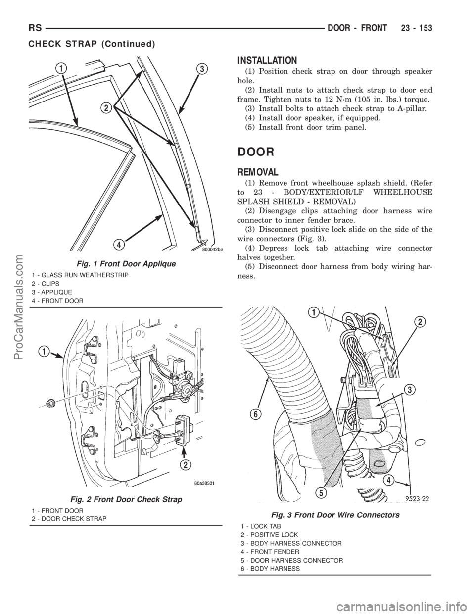
(4) Remove applique from vehicle (Fig. 1) .
INSTALLATION
(1) Position applique on vehicle.
(2)
Hook rear edge of applique over rear edge of door
frame and seat applique bottom edge on sheet metal.
(3) Engage clips to hold front edge of applique to
door frame.
(4) Install outer door belt molding.
CHECK STRAP
REMOVAL
(1) Remove front door watershield. (Refer to 23 -
BODY/DOOR - FRONT/WATERSHIELD -
REMOVAL)
(2) Remove bolts attaching door check strap to
A-pillar (Fig. 4).
(3) Remove nuts attaching check strap to door end
frame (Fig. 2).
(4) Remove check strap from door through speaker
hole.
23 - 152 DOOR - FRONTRS
ProCarManuals.com
Page 2066 of 2321
INSTALLATION
(1) Position check strap on door through speaker
hole.
(2) Install nuts to attach check strap to door end
frame. Tighten nuts to 12 N´m (105 in. lbs.) torque.
(3) Install bolts to attach check strap to A-pillar.
(4) Install door speaker, if equipped.
(5) Install front door trim panel.
DOOR
REMOVAL
(1) Remove front wheelhouse splash shield. (Refer
to 23 - BODY/EXTERIOR/LF WHEELHOUSE
SPLASH SHIELD - REMOVAL)
(2) Disengage clips attaching door harness wire
connector to inner fender brace.
(3) Disconnect positive lock slide on the side of the
wire connectors (Fig. 3).
(4) Depress lock tab attaching wire connector
halves together.
(5) Disconnect door harness from body wiring har-
ness.
Fig. 3 Front Door Wire Connectors
1 - LOCK TAB
2 - POSITIVE LOCK
3 - BODY HARNESS CONNECTOR
4 - FRONT FENDER
5 - DOOR HARNESS CONNECTOR
6 - BODY HARNESS
Fig. 1 Front Door Applique
1 - GLASS RUN WEATHERSTRIP
2 - CLIPS
3 - APPLIQUE
4 - FRONT DOOR
Fig. 2 Front Door Check Strap
1 - FRONT DOOR
2 - DOOR CHECK STRAP
RSDOOR - FRONT23 - 153
CHECK STRAP (Continued)
ProCarManuals.com
Page 2067 of 2321
(6) Remove bolts attaching door check strap to
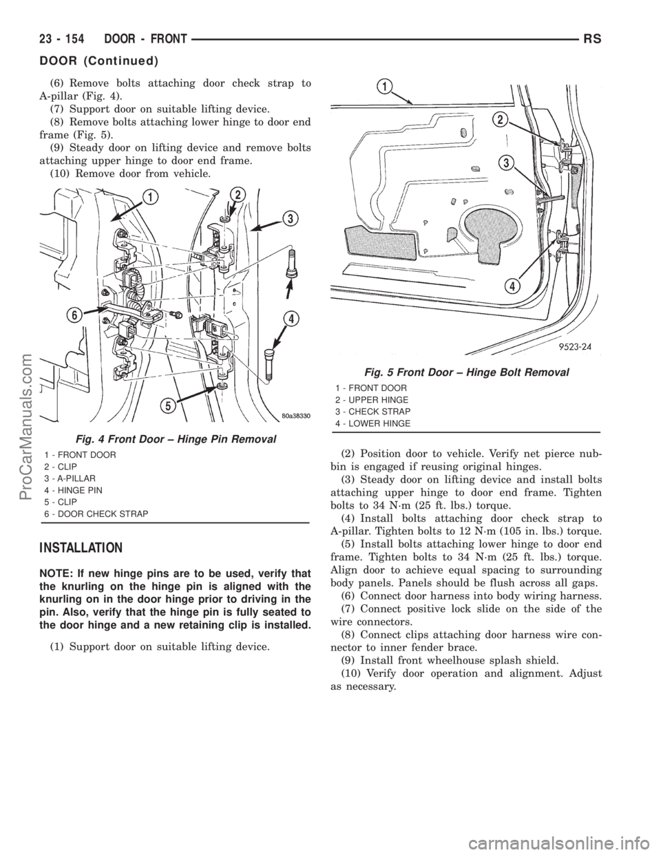
A-pillar (Fig. 4).
(7) Support door on suitable lifting device.
(8) Remove bolts attaching lower hinge to door end
frame (Fig. 5).
(9) Steady door on lifting device and remove bolts
attaching upper hinge to door end frame.
(10) Remove door from vehicle.
INSTALLATION
NOTE: If new hinge pins are to be used, verify that
the knurling on the hinge pin is aligned with the
knurling on in the door hinge prior to driving in the
pin. Also, verify that the hinge pin is fully seated to
the door hinge and a new retaining clip is installed.
(1) Support door on suitable lifting device.(2) Position door to vehicle. Verify net pierce nub-
bin is engaged if reusing original hinges.
(3) Steady door on lifting device and install bolts
attaching upper hinge to door end frame. Tighten
bolts to 34 N´m (25 ft. lbs.) torque.
(4) Install bolts attaching door check strap to
A-pillar. Tighten bolts to 12 N´m (105 in. lbs.) torque.
(5) Install bolts attaching lower hinge to door end
frame. Tighten bolts to 34 N´m (25 ft. lbs.) torque.
Align door to achieve equal spacing to surrounding
body panels. Panels should be flush across all gaps.
(6) Connect door harness into body wiring harness.
(7) Connect positive lock slide on the side of the
wire connectors.
(8) Connect clips attaching door harness wire con-
nector to inner fender brace.
(9) Install front wheelhouse splash shield.
(10) Verify door operation and alignment. Adjust
as necessary.
Fig. 4 Front Door ± Hinge Pin Removal
1 - FRONT DOOR
2 - CLIP
3 - A-PILLAR
4 - HINGE PIN
5 - CLIP
6 - DOOR CHECK STRAP
Fig. 5 Front Door ± Hinge Bolt Removal
1 - FRONT DOOR
2 - UPPER HINGE
3 - CHECK STRAP
4 - LOWER HINGE
23 - 154 DOOR - FRONTRS
DOOR (Continued)
ProCarManuals.com
Page 2069 of 2321
INSTALLATION ± A-PILLAR, HEADER, OR
B-PILLAR
(1) Position closeout molding in window frame.
(2) Insert closeout molding into window frame
channel starting at the corners and working inward.
(3) Verify door glass operation.
HINGE
REMOVAL
(1) Release front door latch and open door.
(2) Support door on suitable lifting device.
(3) Remove bolts holding front door to door hinge.
(4) Remove bolts holding hinge to pillar.
(5) Remove door hinge from vehicle.
INSTALLATION
CAUTION: When installing a new hinge, make sure
that the head of each hinge pin is fully seated into
the door hinge. Also, remove the plastic shipping
clip and replace it with the correct metal retaining
clip once the hinge pin is seated.
(1) Paint hinge prior to installation, if necessary.
(2) Position door hinge on vehicle.
(3) Install bolts to hold hinge to pillar.
(4) Install bolts to hold front door to door hinge.
(5)
Align door to achieve equal spacing to surround-
ing body panels. Panels should be flush across all gaps.
(6) Verify door alignment and operation. Adjust as
necessary.
LATCH
REMOVAL
(1) Roll door glass up.
(2) Remove front door trim panel. (Refer to 23 -
BODY/DOOR - FRONT/TRIM PANEL - REMOVAL)
(3) Remove watershield as necessary to gain access
to the outside door handle.
(4) Through access hole at rear of inner door
panel, disconnect wire connector from power door
lock motor, if equipped.
(5) Disengage clips holding linkage to door latch.
(6) Remove linkages from door latch.
(7) Remove screws attaching door latch to door end
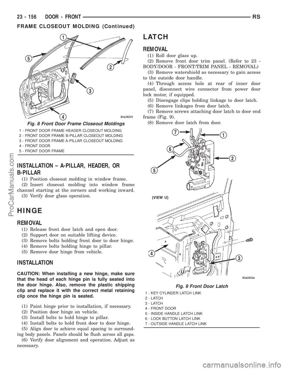
frame (Fig. 9).
(8) Remove door latch from door.
Fig. 8 Front Door Frame Closeout Moldings
1 - FRONT DOOR FRAME HEADER CLOSEOUT MOLDING
2 - FRONT DOOR FRAME B-PILLAR CLOSEOUT MOLDING
3 - FRONT DOOR FRAME A-PILLAR CLOSEOUT MOLDING
4 - FRONT DOOR
5 - FRONT DOOR FRAME
Fig. 9 Front Door Latch
1 - KEY CYLINDER LATCH LINK
2-LATCH
3-LATCH
4 - FRONT DOOR
5 - INSIDE HANDLE LATCH LINK
6 - LOCK BUTTON LATCH LINK
7 - OUTSIDE HANDLE LATCH LINK
23 - 156 DOOR - FRONTRS
FRAME CLOSEOUT MOLDING (Continued)
ProCarManuals.com
Page 2070 of 2321
INSTALLATION
NOTE: The screws attaching the door latch to the
door end frame have nylon patches on the threads.
All screws must be replaced when the latch has
been removed.
(1) Place door latch in position on door end frame.
(2) Install screws attaching door latch to door end
frame. Tighten screws to 10 N´m (90 in. lbs.) torque.
(3) Insert linkage into door latch.
(4) Engage clips attaching linkage to door latch.
(5) Connect wire connector into power door lock
motor, if equipped.
(6) Insert a hex wrench through the elongated hole
located in the door shut face above the latch.
(7) Loosen allen head screw.
(8) Pull outward on the outside door handle and
release.
(9) Tighten allen head screw.
(10)
Verify door latch and power door lock operation.
(11) Install watershield and front door trim panel.
LATCH STRIKER
REMOVAL
(1) Mark outline of door striker on B-pillar to aid
in installation.
(2) Remove screws attaching door latch striker to
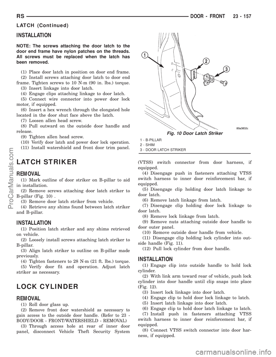
B-pillar (Fig. 10) .
(3) Remove door latch striker from vehicle.
(4) Retrieve any shims found between latch striker
and B-pillar.
INSTALLATION
(1) Position latch striker and any shims retrieved
on vehicle.
(2) Loosely install screws attaching latch striker to
B-pillar.
(3) Align latch striker to outline on B-pillar made
previously.
(4) Tighten fasteners to 28 N´m (21 ft. lbs.) torque.
(5) Verify door fit and operation. Adjust latch
striker as necessary.
LOCK CYLINDER
REMOVAL
(1) Roll door glass up.
(2)
Remove front door watershield as necessary to
gain access to the outside door handle. (Refer to 23 -
BODY/DOOR - FRONT/WATERSHIELD - REMOVAL)
(3) Through access hole at rear of inner door
panel, disconnect Vehicle Theft Security System(VTSS) switch connector from door harness, if
equipped.
(4) Disengage push in fasteners attaching VTSS
switch harness to inner door reinforcement bar, if
equipped.
(5) Disengage clip holding door latch linkage to
door latch.
(6) Remove latch linkage from latch.
(7) Disengage clip holding door lock linkage to
door latch.
(8) Remove lock linkage from latch.
(9) Remove nuts attaching outside door handle to
door outer panel.
(10) Remove outside door handle from vehicle.
(11) Disengage clip holding lock cylinder into out-
side handle (Fig. 11).
(12) Pull lock cylinder from door handle.
INSTALLATION
(1) Engage clip into outside handle to hold lock
cylinder.
(2) With link arm toward rear of vehicle, push lock
cylinder into door handle until clip snaps into place
(Fig. 12).
(3) Insert lock linkage into door latch.
(4) Engage clip to hold door lock linkage to latch.
(5) Insert latch linkage into door latch.
(6) Engage clip to hold door latch linkage to latch.
(7) Install push in fasteners attaching VTSS
switch harness to inner door reinforcement bar, if
equipped.
(8) Connect VTSS switch connector into door har-
ness, if equipped.
Fig. 10 Door Latch Striker
1 - B-PILLAR
2 - SHIM
3 - DOOR LATCH STRIKER
RSDOOR - FRONT23 - 157
LATCH (Continued)
ProCarManuals.com