2001 DODGE TOWN AND COUNTRY door lock
[x] Cancel search: door lockPage 2071 of 2321
(9) Verify door latch operation.
(10) Install watershield and door trim panel.
TRIM PANEL
REMOVAL
(1) Remove the plug and remove screw attaching
door pull cup to inner door panel.
(2) Remove screws attaching trim panel to door
from below map pocket.
(3) If equipped, remove window crank. (Refer to 23
- BODY/DOOR - FRONT/WINDOW CRANK -
REMOVAL)(4) Remove screw holding door trim to door panel
from behind inside latch release handle .
(5) Disengage clips attaching door trim to door
frame around perimeter of panel.
(6) Lift trim panel upward to disengage flange
from inner belt molding at top of door.
(7) Tilt top of trim panel away from door to gain
access to latch linkage.
(8) Disengage clip attaching linkage rod to inside
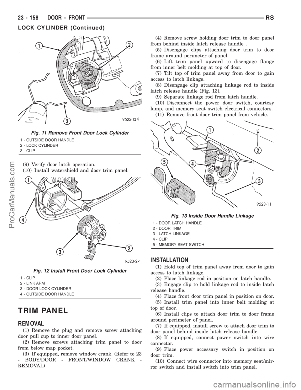
latch release handle (Fig. 13).
(9) Separate linkage rod from latch handle.
(10) Disconnect the power door switch, courtesy
lamp, and memory seat switch electrical connectors.
(11) Remove front door trim panel from vehicle.
INSTALLATION
(1) Hold top of trim panel away from door to gain
access to latch linkage.
(2) Place linkage rod in position on latch handle.
(3) Engage clip to hold linkage rod to inside latch
release handle.
(4) Place front door trim panel in position on door.
(5) Install trim panel into inner belt molding at
top of door.
(6) Install clips to attach door trim to door frame
around perimeter of panel.
(7) If equipped, install screw to attach door trim to
door panel behind inside latch release handle.
(8) If equipped, connect power switch into wire
connector.
(9) Place power accessary switch in position on
door trim.
(10) Connect wire connector into memory seat/mir-
ror switch and install switch into trim panel.
Fig. 11 Remove Front Door Lock Cylinder
1 - OUTSIDE DOOR HANDLE
2 - LOCK CYLINDER
3 - CLIP
Fig. 12 Install Front Door Lock Cylinder
1 - CLIP
2 - LINK ARM
3 - DOOR LOCK CYLINDER
4 - OUTSIDE DOOR HANDLE
Fig. 13 Inside Door Handle Linkage
1 - DOOR LATCH HANDLE
2 - DOOR TRIM
3 - LATCH LINKAGE
4 - CLIP
5 - MEMORY SEAT SWITCH
23 - 158 DOOR - FRONTRS
LOCK CYLINDER (Continued)
ProCarManuals.com
Page 2074 of 2321
EXTERIOR HANDLE
REMOVAL
(1) Roll door glass up.
(2) Remove the watershield. (Refer to 23 - BODY/
DOOR - FRONT/WATERSHIELD - REMOVAL)
(3) Through access hole at rear of inner door
panel, disconnect Vehicle Theft Security System
(VTSS) switch connector from door harness, if
equipped.
(4) Disengage push in fasteners attaching VTSS
switch harness to inner door reinforcement bar, if
equipped.
(5) Disengage clip holding door latch linkage to
door latch.
(6) Remove latch linkage from latch.
(7) Disengage clip holding door lock linkage to
door latch.
(8) Remove lock linkage from latch.
(9) Remove nuts holding outside door handle to
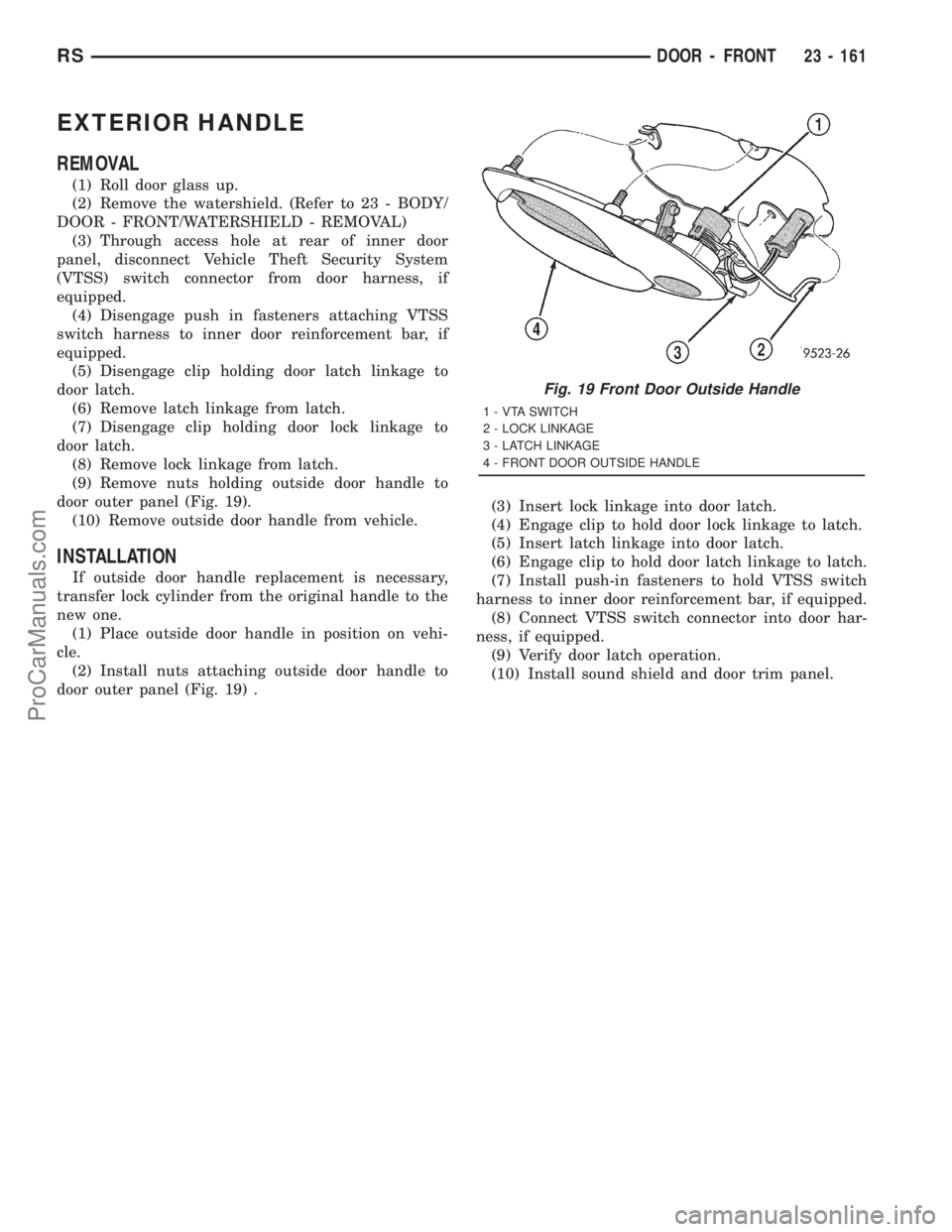
door outer panel (Fig. 19).
(10) Remove outside door handle from vehicle.
INSTALLATION
If outside door handle replacement is necessary,
transfer lock cylinder from the original handle to the
new one.
(1) Place outside door handle in position on vehi-
cle.
(2) Install nuts attaching outside door handle to
door outer panel (Fig. 19) .(3) Insert lock linkage into door latch.
(4) Engage clip to hold door lock linkage to latch.
(5) Insert latch linkage into door latch.
(6) Engage clip to hold door latch linkage to latch.
(7) Install push-in fasteners to hold VTSS switch
harness to inner door reinforcement bar, if equipped.
(8) Connect VTSS switch connector into door har-
ness, if equipped.
(9) Verify door latch operation.
(10) Install sound shield and door trim panel.
Fig. 19 Front Door Outside Handle
1 - VTA SWITCH
2 - LOCK LINKAGE
3 - LATCH LINKAGE
4 - FRONT DOOR OUTSIDE HANDLE
RSDOOR - FRONT23 - 161
ProCarManuals.com
Page 2075 of 2321
DOORS - SLIDING
TABLE OF CONTENTS
page page
CENTER HINGE
REMOVAL.............................162
INSTALLATION..........................162
CENTER STOP TRIM COVER
REMOVAL.............................163
INSTALLATION..........................163
STOP BUMPER
REMOVAL.............................163
INSTALLATION..........................163
HOLD OPEN LATCH
REMOVAL.............................163
INSTALLATION..........................164
HOLD OPEN LATCH STRIKER
REMOVAL.............................164
INSTALLATION..........................164
LATCH / LOCK CONTROL
REMOVAL.............................164
INSTALLATION..........................165
LOWER ROLLER ARM
REMOVAL.............................166
INSTALLATION..........................167
LOWER ROLLER ARM BRACKET
REMOVAL.............................167
INSTALLATION..........................167
REAR LATCH
REMOVAL.............................168
INSTALLATION..........................168
CENTER LATCH STRIKER
REMOVAL.............................168
INSTALLATION..........................168
REAR LATCH STRIKER
REMOVAL.............................169
INSTALLATION..........................169
SLIDING DOOR
REMOVAL.............................169INSTALLATION..........................170
ADJUSTMENTS.........................171
STABILIZER
REMOVAL.............................173
INSTALLATION..........................173
STABILIZER SOCKET
REMOVAL.............................173
INSTALLATION..........................173
TRIM PANEL
REMOVAL.............................174
INSTALLATION..........................174
INSIDE LATCH HANDLE
REMOVAL.............................174
INSTALLATION..........................174
INSIDE LATCH HANDLE BELLCRANK
REMOVAL.............................175
INSTALLATION..........................175
INSIDE LATCH RELEASE MECHANISM
REMOVAL.............................175
INSTALLATION..........................176
EXTERIOR HANDLE
REMOVAL.............................176
INSTALLATION..........................176
UPPER ROLLER
REMOVAL.............................177
INSTALLATION..........................177
OUTSIDE HANDLE CABLE
REMOVAL.............................177
INSTALLATION..........................178
INSIDE HANDLE CABLE
REMOVAL.............................178
INSTALLATION..........................178
HOLD OPEN LATCH CABLE
REMOVAL.............................179
INSTALLATION..........................179
CENTER HINGE
REMOVAL
NOTE: For power sliding door procedures refer to
POWER SLIDING DOOR SYSTEM in the ELECTRI-
CAL section.
(1) Open sliding door to the mid point of its travel.
(2) Support sliding door on a suitable lifting
device.(3) Mark outline of center hinge of inner door
panel to aid installation.
(4) Remove bolts holding center hinge to sliding
door.
(5) Remove center hinge from sliding door.
(6) Roll center hinge to rear of roller channel.
(7) Separate center hinge from vehicle.
INSTALLATION
NOTE: For power sliding door procedures refer to
POWER SLIDING DOOR SYSTEM in the ELECTRI-
CAL section.
23 - 162 DOORS - SLIDINGRS
ProCarManuals.com
Page 2077 of 2321
INSTALLATION
(1) Place hold open latch in position on vehicle.
(2) Connect cable to hold open latch.
(3) Place hold open latch in position on lower arm.
(4) Install nuts to hold the hold open latch to
lower roller arm.
(5) Install sliding door sill plate. (Refer to 23 -
BODY/INTERIOR/SLIDING DOOR SILL PLATE -
INSTALLATION)
(6) Verify sliding door operation.
HOLD OPEN LATCH STRIKER
REMOVAL
NOTE: For power sliding door procedures refer to
POWER SLIDING DOOR SYSTEM in the ELECTRI-
CAL section.
(1) Open sliding door, do not latch open.
(2) Remove sliding door sill plate. (Refer to 23 -
BODY/INTERIOR/SLIDING DOOR SILL PLATE -
REMOVAL)
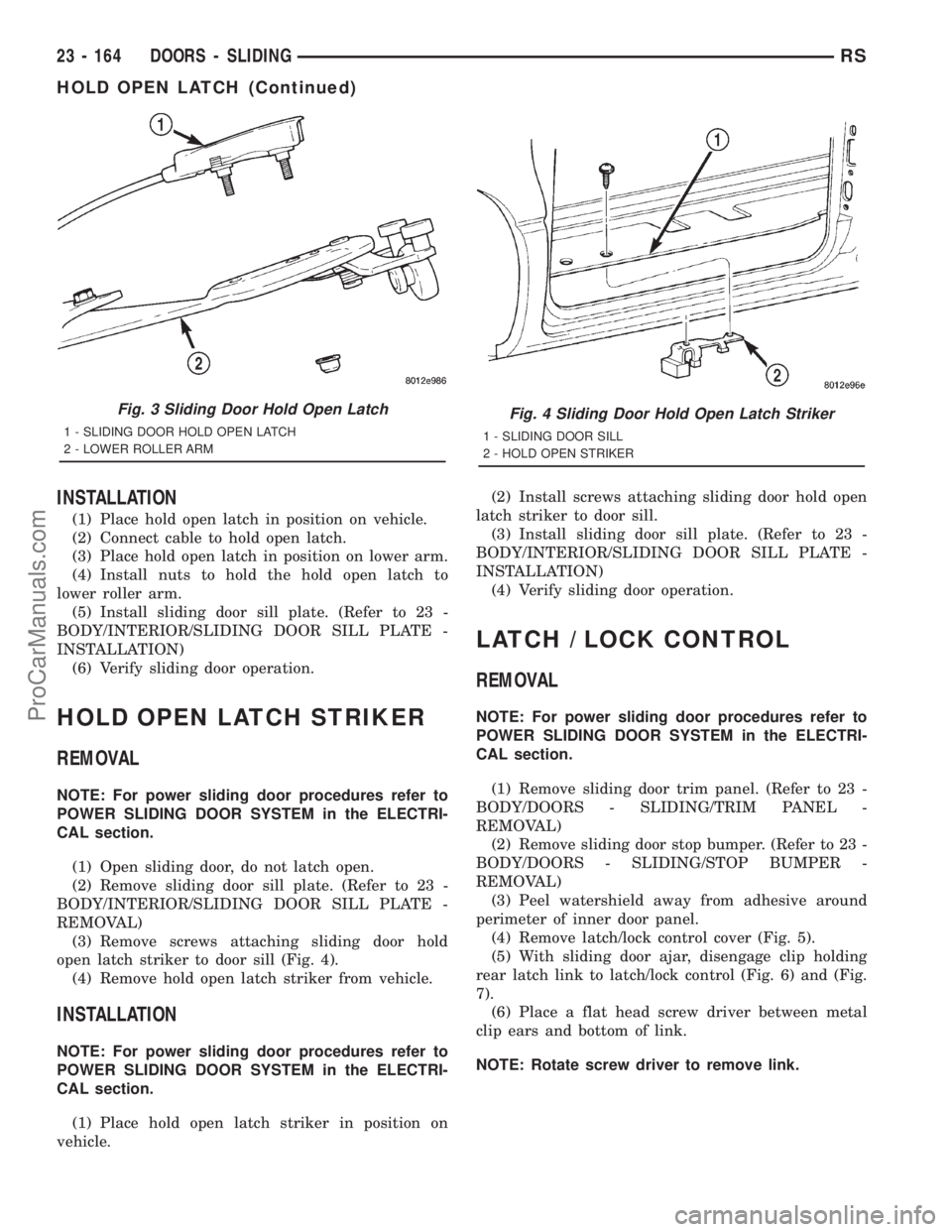
(3) Remove screws attaching sliding door hold
open latch striker to door sill (Fig. 4).
(4) Remove hold open latch striker from vehicle.
INSTALLATION
NOTE: For power sliding door procedures refer to
POWER SLIDING DOOR SYSTEM in the ELECTRI-
CAL section.
(1) Place hold open latch striker in position on
vehicle.(2) Install screws attaching sliding door hold open
latch striker to door sill.
(3) Install sliding door sill plate. (Refer to 23 -
BODY/INTERIOR/SLIDING DOOR SILL PLATE -
INSTALLATION)
(4) Verify sliding door operation.
LATCH / LOCK CONTROL
REMOVAL
NOTE: For power sliding door procedures refer to
POWER SLIDING DOOR SYSTEM in the ELECTRI-
CAL section.
(1) Remove sliding door trim panel. (Refer to 23 -
BODY/DOORS - SLIDING/TRIM PANEL -
REMOVAL)
(2) Remove sliding door stop bumper. (Refer to 23 -
BODY/DOORS - SLIDING/STOP BUMPER -
REMOVAL)
(3) Peel watershield away from adhesive around
perimeter of inner door panel.
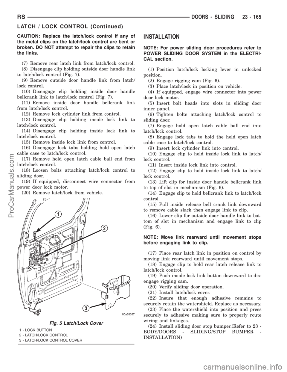
(4) Remove latch/lock control cover (Fig. 5).
(5) With sliding door ajar, disengage clip holding
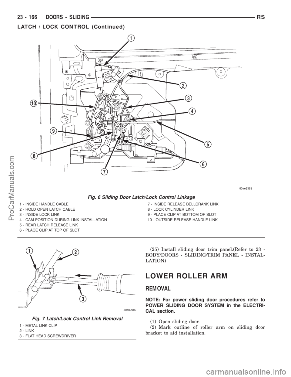
rear latch link to latch/lock control (Fig. 6) and (Fig.
7).
(6) Place a flat head screw driver between metal
clip ears and bottom of link.
NOTE: Rotate screw driver to remove link.
Fig. 3 Sliding Door Hold Open Latch
1 - SLIDING DOOR HOLD OPEN LATCH
2 - LOWER ROLLER ARM
Fig. 4 Sliding Door Hold Open Latch Striker
1 - SLIDING DOOR SILL
2 - HOLD OPEN STRIKER
23 - 164 DOORS - SLIDINGRS
HOLD OPEN LATCH (Continued)
ProCarManuals.com
Page 2078 of 2321
CAUTION: Replace the latch/lock control if any of
the metal clips on the latch/lock control are bent or
broken. DO NOT attempt to repair the clips to retain
the links.
(7) Remove rear latch link from latch/lock control.
(8) Disengage clip holding outside door handle link
to latch/lock control (Fig. 7).
(9) Remove outside door handle link from latch/
lock control.
(10) Disengage clip holding inside door handle
bellcrank link to latch/lock control (Fig. 7).
(11) Remove inside door handle bellcrank link
from latch/lock control.
(12) Remove lock cylinder link from control.
(13) Disengage clip holding inside lock link to
latch/lock control.
(14) Disengage clip holding inside lock link to
latch/lock control.
(15) Remove inside lock link from control.
(16) Disengage lock tabs holding hold open latch
cable case to latch/lock control.
(17) Remove hold open latch cable ball end from
latch/lock control.
(18) Loosen bolts attaching latch/lock control to
sliding door.
(19) If equipped, disconnect wire connector from
power door lock motor.
(20) Remove latch/lock from vehicle.INSTALLATION
NOTE: For power sliding door procedures refer to
POWER SLIDING DOOR SYSTEM in the ELECTRI-
CAL section.
(1) Position latch/lock locking lever in unlocked
position.
(2) Engage rigging cam (Fig. 6).
(3) Place latch/lock in position on vehicle.
(4) If equipped, engage wire connector into power
door lock motor.
(5) Insert bolt heads into slots in sliding door
inner panel.
(6) Tighten bolts attaching latch/lock control to
sliding door.
(7) Engage hold open latch cable ball end into
latch/lock control.
(8) Engage lock tabs to hold the hold open latch
cable case to latch/lock control.
(9) Insert lock cylinder link into control.
(10) Engage clip to hold inside lock link to latch/
lock control.
(11) Insert inside lock link into control.
(12) Engage clip to hold inside lock link to latch/
lock control.
(13) Lift clip for inside door handle bellcrank link
to top of slot in mechanism (Fig. 6).
(14) Engage clip to hold bellcrank link to latch/lock
control.
(15) Pull inside release bell crank link downward
to remove cable slack then engage link to clip.
(16) Lower clip for outside door handle link to bot-
tom of slot in mechanism and engage link to clip
(Fig. 6).
NOTE: Move link rearward until movement stops
before engaging link to clip.
(17) Place rear latch link in position on control by
moving link rearward until movement stops.
(18) Engage clip to hold rear latch release link to
latch/lock control.
(19) Push inside lock link button downward to dis-
engage rigging cam.
(20) Verify sliding door operation.
(21) Install latch/lock cover.
(22) Insure that enough adhesive remains to
securely retain the watershield. Replace as necessary.
(23) Place the watershield into position and press
securely to adhesive making sure to properly route
wiring and linkages.
(24) Install sliding door stop bumper.(Refer to 23 -
BODY/DOORS - SLIDING/STOP BUMPER -
INSTALLATION)
Fig. 5 Latch/Lock Cover
1 - LOCK BUTTON
2 - LATCH/LOCK CONTROL
3 - LATCH/LOCK CONTROL COVER
RSDOORS - SLIDING23 - 165
LATCH / LOCK CONTROL (Continued)
ProCarManuals.com
Page 2079 of 2321
(25) Install sliding door trim panel.(Refer to 23 -
BODY/DOORS - SLIDING/TRIM PANEL - INSTAL-
LATION)
LOWER ROLLER ARM
REMOVAL
NOTE: For power sliding door procedures refer to
POWER SLIDING DOOR SYSTEM in the ELECTRI-
CAL section.
(1) Open sliding door.
(2) Mark outline of roller arm on sliding door
bracket to aid installation.
Fig. 6 Sliding Door Latch/Lock Control Linkage
1 - INSIDE HANDLE CABLE
2 - HOLD OPEN LATCH CABLE
3 - INSIDE LOCK LINK
4 - CAM POSITION DURING LINK INSTALLATION
5 - REAR LATCH RELEASE LINK
6 - PLACE CLIP AT TOP OF SLOT7 - INSIDE RELEASE BELLCRANK LINK
8 - LOCK CYLINDER LINK
9 - PLACE CLIP AT BOTTOM OF SLOT
10 - OUTSIDE RELEASE HANDLE LINK
Fig. 7 Latch/Lock Control Link Removal
1 - METAL LINK CLIP
2 - LINK
3 - FLAT HEAD SCREWDRIVER
23 - 166 DOORS - SLIDINGRS
LATCH / LOCK CONTROL (Continued)
ProCarManuals.com
Page 2081 of 2321
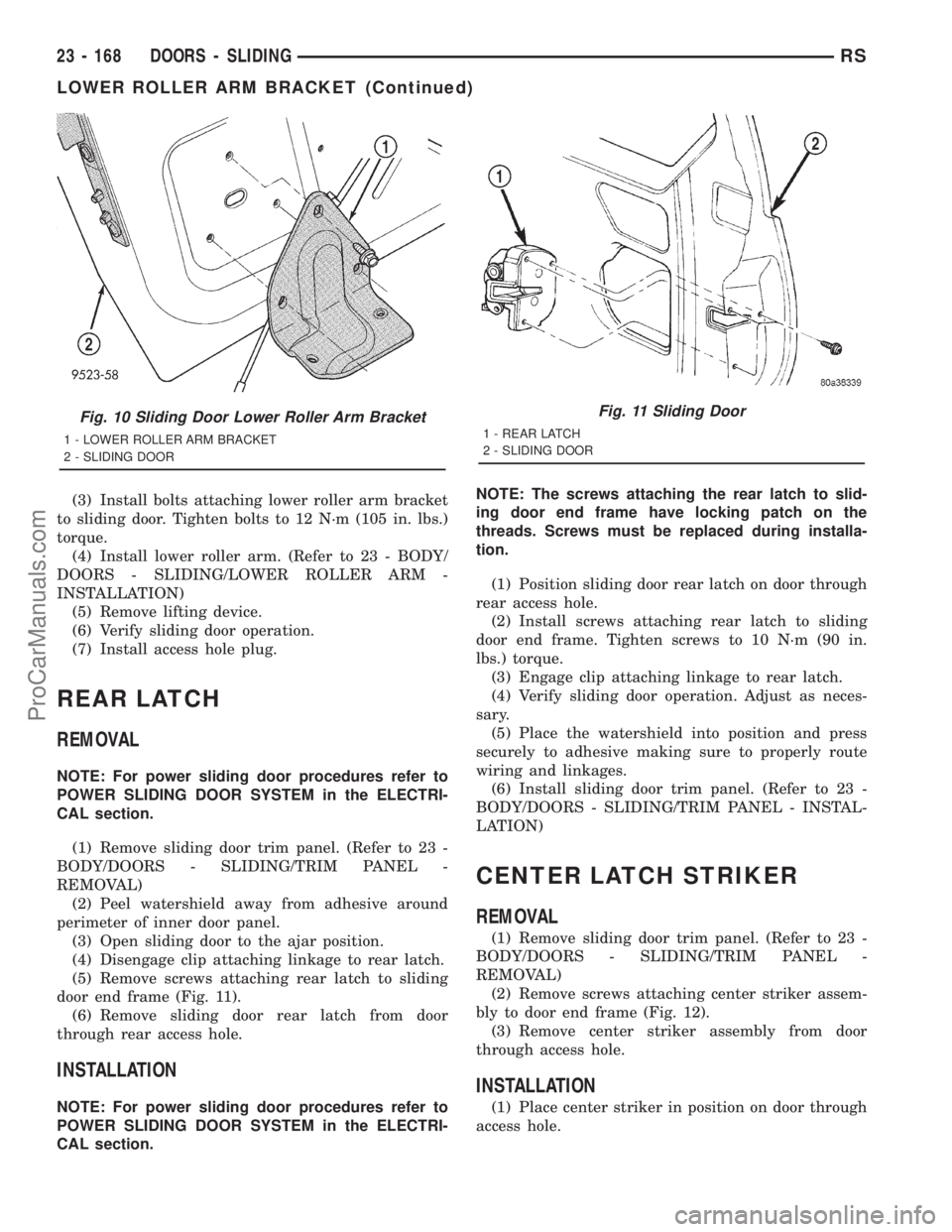
(3) Install bolts attaching lower roller arm bracket
to sliding door. Tighten bolts to 12 N´m (105 in. lbs.)
torque.
(4) Install lower roller arm. (Refer to 23 - BODY/
DOORS - SLIDING/LOWER ROLLER ARM -
INSTALLATION)
(5) Remove lifting device.
(6) Verify sliding door operation.
(7) Install access hole plug.
REAR LATCH
REMOVAL
NOTE: For power sliding door procedures refer to
POWER SLIDING DOOR SYSTEM in the ELECTRI-
CAL section.
(1) Remove sliding door trim panel. (Refer to 23 -
BODY/DOORS - SLIDING/TRIM PANEL -
REMOVAL)
(2) Peel watershield away from adhesive around
perimeter of inner door panel.
(3) Open sliding door to the ajar position.
(4) Disengage clip attaching linkage to rear latch.
(5) Remove screws attaching rear latch to sliding
door end frame (Fig. 11).
(6) Remove sliding door rear latch from door
through rear access hole.
INSTALLATION
NOTE: For power sliding door procedures refer to
POWER SLIDING DOOR SYSTEM in the ELECTRI-
CAL section.NOTE: The screws attaching the rear latch to slid-
ing door end frame have locking patch on the
threads. Screws must be replaced during installa-
tion.
(1) Position sliding door rear latch on door through
rear access hole.
(2) Install screws attaching rear latch to sliding
door end frame. Tighten screws to 10 N´m (90 in.
lbs.) torque.
(3) Engage clip attaching linkage to rear latch.
(4) Verify sliding door operation. Adjust as neces-
sary.
(5) Place the watershield into position and press
securely to adhesive making sure to properly route
wiring and linkages.
(6) Install sliding door trim panel. (Refer to 23 -
BODY/DOORS - SLIDING/TRIM PANEL - INSTAL-
LATION)
CENTER LATCH STRIKER
REMOVAL
(1) Remove sliding door trim panel. (Refer to 23 -
BODY/DOORS - SLIDING/TRIM PANEL -
REMOVAL)
(2) Remove screws attaching center striker assem-
bly to door end frame (Fig. 12).
(3) Remove center striker assembly from door
through access hole.
INSTALLATION
(1) Place center striker in position on door through
access hole.
Fig. 10 Sliding Door Lower Roller Arm Bracket
1 - LOWER ROLLER ARM BRACKET
2 - SLIDING DOOR
Fig. 11 Sliding Door
1 - REAR LATCH
2 - SLIDING DOOR
23 - 168 DOORS - SLIDINGRS
LOWER ROLLER ARM BRACKET (Continued)
ProCarManuals.com
Page 2084 of 2321
(8) Install center roller channel end cover (Fig. 16).
(9) Install center stop on sliding door. (Refer to 23
- BODY/DOORS - SLIDING/STOP BUMPER -
INSTALLATION)
(10) Place upper roller stop bumper in position on
upper roller arm.
(11) Install screw to hold upper roller arm stop
bumper to upper roller arm (Fig. 14).
(12) Remove masking tape from body surfaces.
(13) Verify door operation and fit. Adjust as neces-
sary. (Refer to 23 - BODY/DOORS - SLIDING/SLID-
ING DOOR - ADJUSTMENTS)
SLIDING DOOR ADJUSTMENTS
NOTE: For power sliding door procedures refer to
POWER SLIDING DOOR SYSTEM in the ELECTRI-
CAL section.
PRELIMINARY CHECKS
(1) Close the sliding door, visually checking C-post
striker alignment entry into latch. Striker at this
point must not affect alignment. Striker should go
straight into the latching mechanism.
(2) On vehicles with left sliding doors, check the
fuel door blocker striker entry into latch. Striker at
this point must not affect alignment.
(3) Check C-post and B-post for door to aperture
gaps and door to door gaps. All gaps should be 5 mm
1 mm.
(4) Check door for height using character lines as
a reference. Also check roof contour as a controlling
factor.
Using the procedures noted below, adjust the side
door in the order the individual steps are called out.
DOOR FLUSHNESS ADJUSTMENT
(1) Check sliding door flushness at the C-pillar
striker.
(2) Adjust the C-pillar striker in or out untill the
door is flush.
(3) Check upper B-pillar flushness to A-pillar
cover.
(4) Loosen one nut on upper hinge and adjust door
in or out untill the door is flush.
(5) Check flushness at upper C-pillar.
(6) If upper C-pillar flushness is out of specifica-
tion use a heavy rubber malet on the door assembly
until door is in spec.
DOOR GAP ADJUSTMENT - UP/DOWN
UP/DOWN ADJUSTMENT
(1) Visually inspect the sliding door for fitting low
at the top of the door by checking the alignment of
the top contour of the door to the quarter panel.(2) Fully open the sliding door.
(3) Verify that all center hinge bolts are tight.
(4) Adjust the rear of the sliding door up by turn-
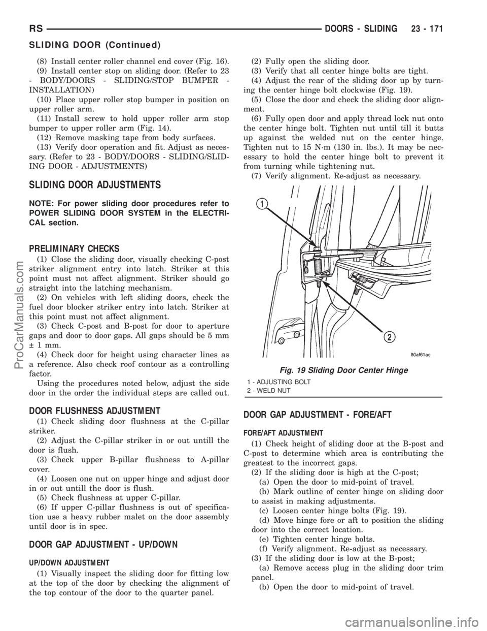
ing the center hinge bolt clockwise (Fig. 19).
(5) Close the door and check the sliding door align-
ment.
(6) Fully open door and apply thread lock nut onto
the center hinge bolt. Tighten nut until till it butts
up against the welded nut on the center hinge.
Tighten nut to 15 N´m (130 in. lbs.). It may be nec-
essary to hold the center hinge bolt to prevent it
from turning while tightening nut.
(7) Verify alignment. Re-adjust as necessary.
DOOR GAP ADJUSTMENT - FORE/AFT
FORE/AFT ADJUSTMENT
(1) Check height of sliding door at the B-post and
C-post to determine which area is contributing the
greatest to the incorrect gaps.
(2) If the sliding door is high at the C-post;
(a) Open the door to mid-point of travel.
(b) Mark outline of center hinge on sliding door
to assist in making adjustments.
(c) Loosen center hinge bolts (Fig. 19).
(d) Move hinge fore or aft to position the sliding
door into the correct location.
(e) Tighten center hinge bolts.
(f) Verify alignment. Re-adjust as necessary.
(3) If the sliding door is low at the B-post;
(a) Remove access plug in the sliding door trim
panel.
(b) Open the door to mid-point of travel.
Fig. 19 Sliding Door Center Hinge
1 - ADJUSTING BOLT
2 - WELD NUT
RSDOORS - SLIDING23 - 171
SLIDING DOOR (Continued)
ProCarManuals.com