2001 DODGE TOWN AND COUNTRY door lock
[x] Cancel search: door lockPage 1101 of 2321
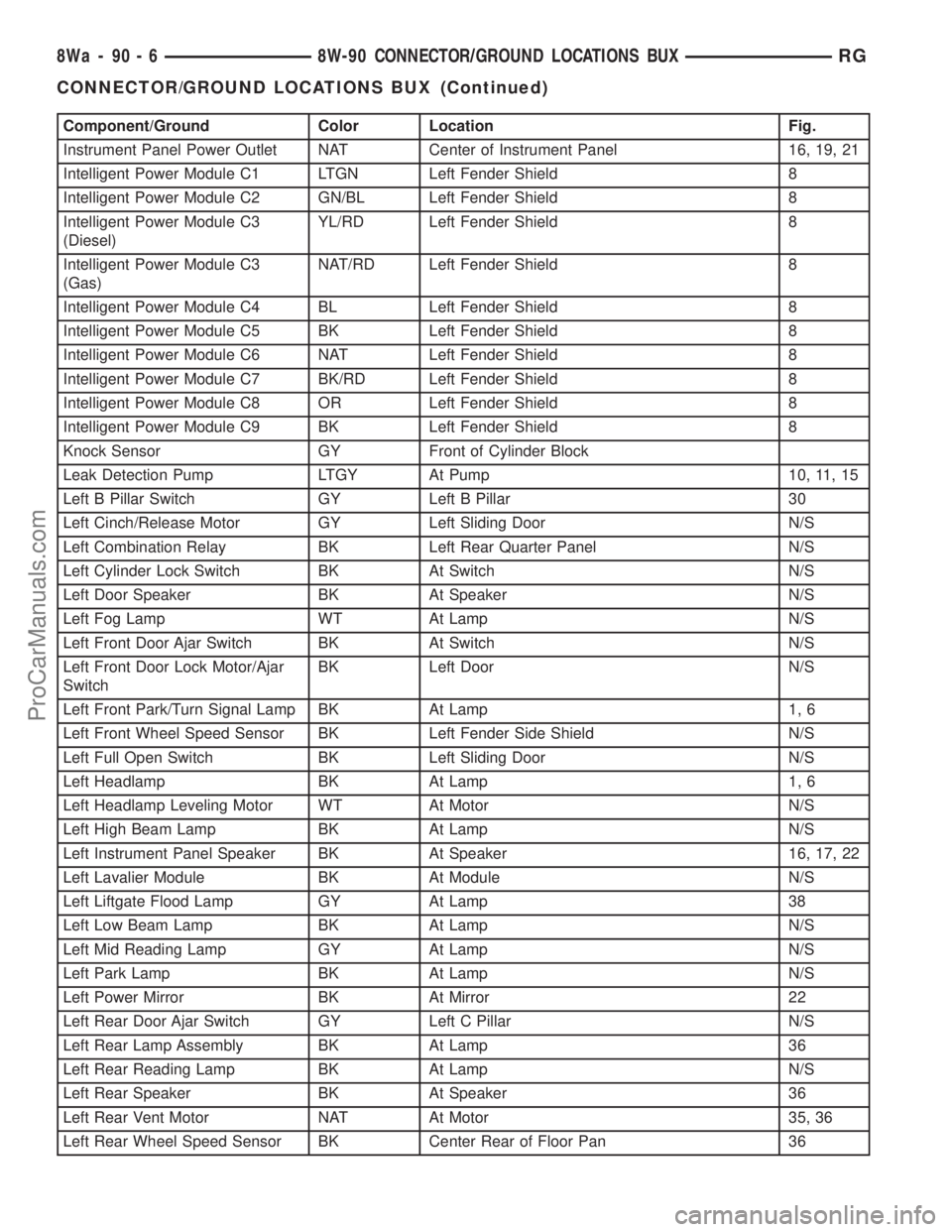
Component/Ground Color Location Fig.
Instrument Panel Power Outlet NAT Center of Instrument Panel 16, 19, 21
Intelligent Power Module C1 LTGN Left Fender Shield 8
Intelligent Power Module C2 GN/BL Left Fender Shield 8
Intelligent Power Module C3
(Diesel)YL/RD Left Fender Shield 8
Intelligent Power Module C3
(Gas)NAT/RD Left Fender Shield 8
Intelligent Power Module C4 BL Left Fender Shield 8
Intelligent Power Module C5 BK Left Fender Shield 8
Intelligent Power Module C6 NAT Left Fender Shield 8
Intelligent Power Module C7 BK/RD Left Fender Shield 8
Intelligent Power Module C8 OR Left Fender Shield 8
Intelligent Power Module C9 BK Left Fender Shield 8
Knock Sensor GY Front of Cylinder Block
Leak Detection Pump LTGY At Pump 10, 11, 15
Left B Pillar Switch GY Left B Pillar 30
Left Cinch/Release Motor GY Left Sliding Door N/S
Left Combination Relay BK Left Rear Quarter Panel N/S
Left Cylinder Lock Switch BK At Switch N/S
Left Door Speaker BK At Speaker N/S
Left Fog Lamp WT At Lamp N/S
Left Front Door Ajar Switch BK At Switch N/S
Left Front Door Lock Motor/Ajar
SwitchBK Left Door N/S
Left Front Park/Turn Signal Lamp BK At Lamp 1, 6
Left Front Wheel Speed Sensor BK Left Fender Side Shield N/S
Left Full Open Switch BK Left Sliding Door N/S
Left Headlamp BK At Lamp 1, 6
Left Headlamp Leveling Motor WT At Motor N/S
Left High Beam Lamp BK At Lamp N/S
Left Instrument Panel Speaker BK At Speaker 16, 17, 22
Left Lavalier Module BK At Module N/S
Left Liftgate Flood Lamp GY At Lamp 38
Left Low Beam Lamp BK At Lamp N/S
Left Mid Reading Lamp GY At Lamp N/S
Left Park Lamp BK At Lamp N/S
Left Power Mirror BK At Mirror 22
Left Rear Door Ajar Switch GY Left C Pillar N/S
Left Rear Lamp Assembly BK At Lamp 36
Left Rear Reading Lamp BK At Lamp N/S
Left Rear Speaker BK At Speaker 36
Left Rear Vent Motor NAT At Motor 35, 36
Left Rear Wheel Speed Sensor BK Center Rear of Floor Pan 36
8Wa - 90 - 6 8W-90 CONNECTOR/GROUND LOCATIONS BUXRG
CONNECTOR/GROUND LOCATIONS BUX (Continued)
ProCarManuals.com
Page 1102 of 2321
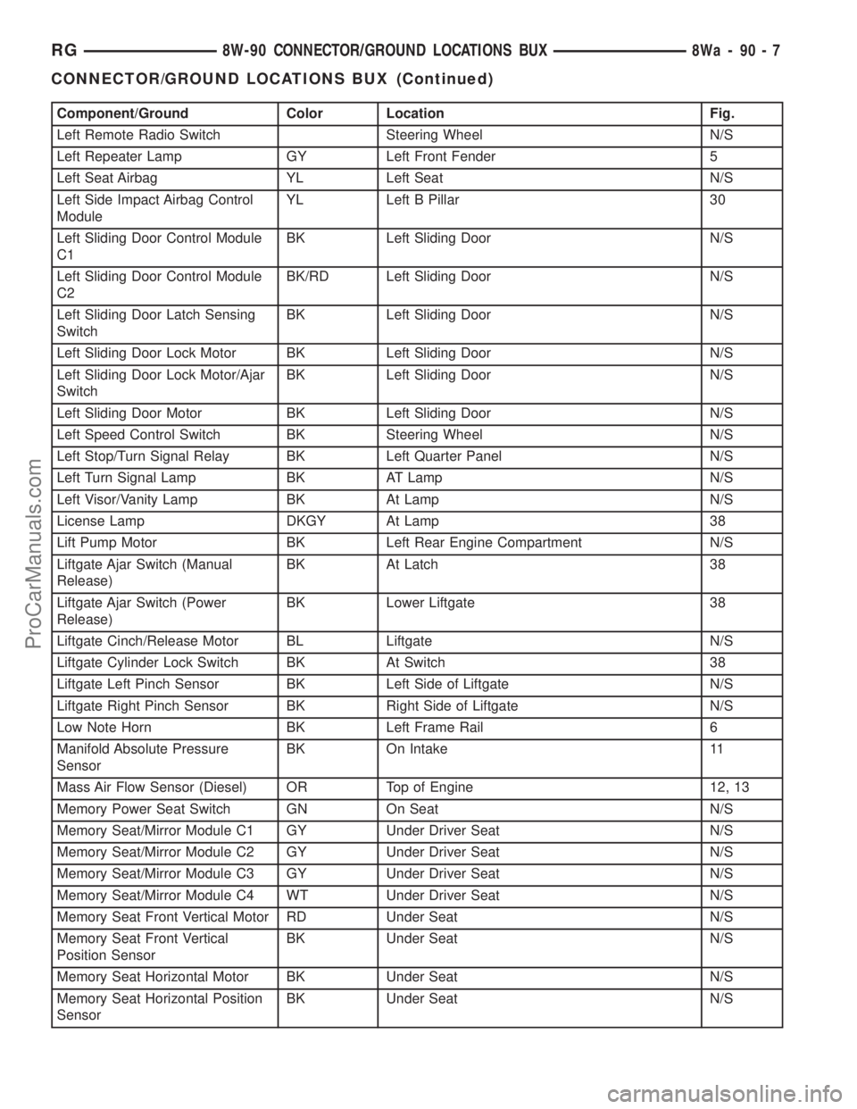
Component/Ground Color Location Fig.
Left Remote Radio Switch Steering Wheel N/S
Left Repeater Lamp GY Left Front Fender 5
Left Seat Airbag YL Left Seat N/S
Left Side Impact Airbag Control
ModuleYL Left B Pillar 30
Left Sliding Door Control Module
C1BK Left Sliding Door N/S
Left Sliding Door Control Module
C2BK/RD Left Sliding Door N/S
Left Sliding Door Latch Sensing
SwitchBK Left Sliding Door N/S
Left Sliding Door Lock Motor BK Left Sliding Door N/S
Left Sliding Door Lock Motor/Ajar
SwitchBK Left Sliding Door N/S
Left Sliding Door Motor BK Left Sliding Door N/S
Left Speed Control Switch BK Steering Wheel N/S
Left Stop/Turn Signal Relay BK Left Quarter Panel N/S
Left Turn Signal Lamp BK AT Lamp N/S
Left Visor/Vanity Lamp BK At Lamp N/S
License Lamp DKGY At Lamp 38
Lift Pump Motor BK Left Rear Engine Compartment N/S
Liftgate Ajar Switch (Manual
Release)BK At Latch 38
Liftgate Ajar Switch (Power
Release)BK Lower Liftgate 38
Liftgate Cinch/Release Motor BL Liftgate N/S
Liftgate Cylinder Lock Switch BK At Switch 38
Liftgate Left Pinch Sensor BK Left Side of Liftgate N/S
Liftgate Right Pinch Sensor BK Right Side of Liftgate N/S
Low Note Horn BK Left Frame Rail 6
Manifold Absolute Pressure
SensorBK On Intake 11
Mass Air Flow Sensor (Diesel) OR Top of Engine 12, 13
Memory Power Seat Switch GN On Seat N/S
Memory Seat/Mirror Module C1 GY Under Driver Seat N/S
Memory Seat/Mirror Module C2 GY Under Driver Seat N/S
Memory Seat/Mirror Module C3 GY Under Driver Seat N/S
Memory Seat/Mirror Module C4 WT Under Driver Seat N/S
Memory Seat Front Vertical Motor RD Under Seat N/S
Memory Seat Front Vertical
Position SensorBK Under Seat N/S
Memory Seat Horizontal Motor BK Under Seat N/S
Memory Seat Horizontal Position
SensorBK Under Seat N/S
RG8W-90 CONNECTOR/GROUND LOCATIONS BUX8Wa-90-7
CONNECTOR/GROUND LOCATIONS BUX (Continued)
ProCarManuals.com
Page 1103 of 2321
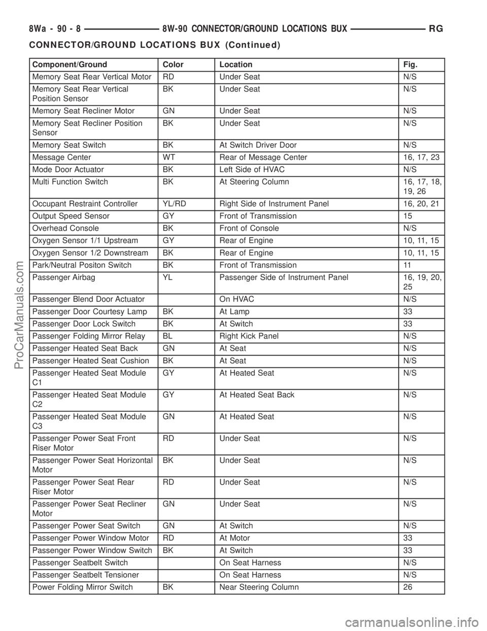
Component/Ground Color Location Fig.
Memory Seat Rear Vertical Motor RD Under Seat N/S
Memory Seat Rear Vertical
Position SensorBK Under Seat N/S
Memory Seat Recliner Motor GN Under Seat N/S
Memory Seat Recliner Position
SensorBK Under Seat N/S
Memory Seat Switch BK At Switch Driver Door N/S
Message Center WT Rear of Message Center 16, 17, 23
Mode Door Actuator BK Left Side of HVAC N/S
Multi Function Switch BK At Steering Column 16, 17, 18,
19, 26
Occupant Restraint Controller YL/RD Right Side of Instrument Panel 16, 20, 21
Output Speed Sensor GY Front of Transmission 15
Overhead Console BK Front of Console N/S
Oxygen Sensor 1/1 Upstream GY Rear of Engine 10, 11, 15
Oxygen Sensor 1/2 Downstream BK Rear of Engine 10, 11, 15
Park/Neutral Positon Switch BK Front of Transmission 11
Passenger Airbag YL Passenger Side of Instrument Panel 16, 19, 20,
25
Passenger Blend Door Actuator On HVAC N/S
Passenger Door Courtesy Lamp BK At Lamp 33
Passenger Door Lock Switch BK At Switch 33
Passenger Folding Mirror Relay BL Right Kick Panel N/S
Passenger Heated Seat Back GN At Seat N/S
Passenger Heated Seat Cushion BK At Seat N/S
Passenger Heated Seat Module
C1GY At Heated Seat N/S
Passenger Heated Seat Module
C2GY At Heated Seat Back N/S
Passenger Heated Seat Module
C3GN At Heated Seat N/S
Passenger Power Seat Front
Riser MotorRD Under Seat N/S
Passenger Power Seat Horizontal
MotorBK Under Seat N/S
Passenger Power Seat Rear
Riser MotorRD Under Seat N/S
Passenger Power Seat Recliner
MotorGN Under Seat N/S
Passenger Power Seat Switch GN At Switch N/S
Passenger Power Window Motor RD At Motor 33
Passenger Power Window Switch BK At Switch 33
Passenger Seatbelt Switch On Seat Harness N/S
Passenger Seatbelt Tensioner On Seat Harness N/S
Power Folding Mirror Switch BK Near Steering Column 26
8Wa - 90 - 8 8W-90 CONNECTOR/GROUND LOCATIONS BUXRG
CONNECTOR/GROUND LOCATIONS BUX (Continued)
ProCarManuals.com
Page 1104 of 2321
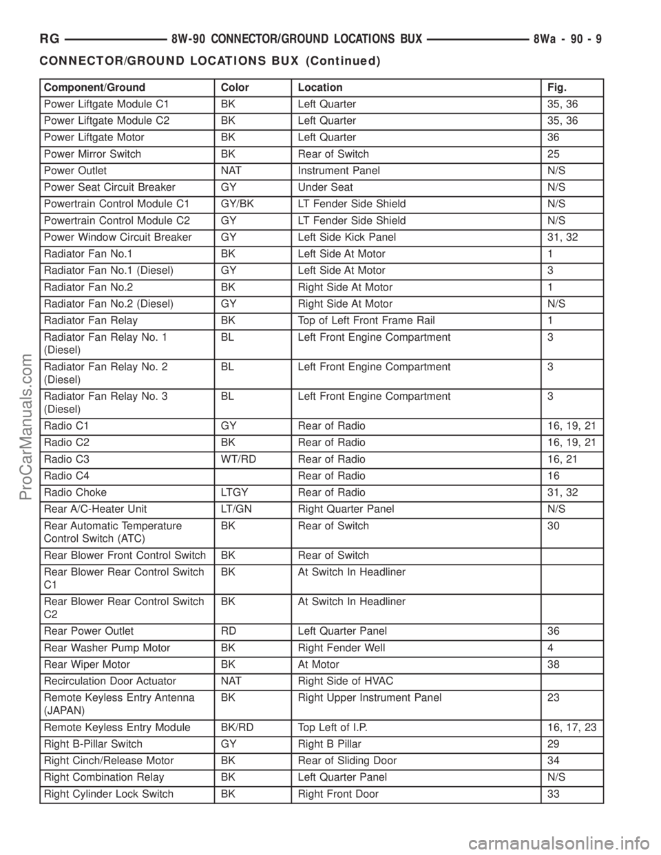
Component/Ground Color Location Fig.
Power Liftgate Module C1 BK Left Quarter 35, 36
Power Liftgate Module C2 BK Left Quarter 35, 36
Power Liftgate Motor BK Left Quarter 36
Power Mirror Switch BK Rear of Switch 25
Power Outlet NAT Instrument Panel N/S
Power Seat Circuit Breaker GY Under Seat N/S
Powertrain Control Module C1 GY/BK LT Fender Side Shield N/S
Powertrain Control Module C2 GY LT Fender Side Shield N/S
Power Window Circuit Breaker GY Left Side Kick Panel 31, 32
Radiator Fan No.1 BK Left Side At Motor 1
Radiator Fan No.1 (Diesel) GY Left Side At Motor 3
Radiator Fan No.2 BK Right Side At Motor 1
Radiator Fan No.2 (Diesel) GY Right Side At Motor N/S
Radiator Fan Relay BK Top of Left Front Frame Rail 1
Radiator Fan Relay No. 1
(Diesel)BL Left Front Engine Compartment 3
Radiator Fan Relay No. 2
(Diesel)BL Left Front Engine Compartment 3
Radiator Fan Relay No. 3
(Diesel)BL Left Front Engine Compartment 3
Radio C1 GY Rear of Radio 16, 19, 21
Radio C2 BK Rear of Radio 16, 19, 21
Radio C3 WT/RD Rear of Radio 16, 21
Radio C4 Rear of Radio 16
Radio Choke LTGY Rear of Radio 31, 32
Rear A/C-Heater Unit LT/GN Right Quarter Panel N/S
Rear Automatic Temperature
Control Switch (ATC)BK Rear of Switch 30
Rear Blower Front Control Switch BK Rear of Switch
Rear Blower Rear Control Switch
C1BK At Switch In Headliner
Rear Blower Rear Control Switch
C2BK At Switch In Headliner
Rear Power Outlet RD Left Quarter Panel 36
Rear Washer Pump Motor BK Right Fender Well 4
Rear Wiper Motor BK At Motor 38
Recirculation Door Actuator NAT Right Side of HVAC
Remote Keyless Entry Antenna
(JAPAN)BK Right Upper Instrument Panel 23
Remote Keyless Entry Module BK/RD Top Left of I.P. 16, 17, 23
Right B-Pillar Switch GY Right B Pillar 29
Right Cinch/Release Motor BK Rear of Sliding Door 34
Right Combination Relay BK Left Quarter Panel N/S
Right Cylinder Lock Switch BK Right Front Door 33
RG8W-90 CONNECTOR/GROUND LOCATIONS BUX8Wa-90-9
CONNECTOR/GROUND LOCATIONS BUX (Continued)
ProCarManuals.com
Page 1105 of 2321
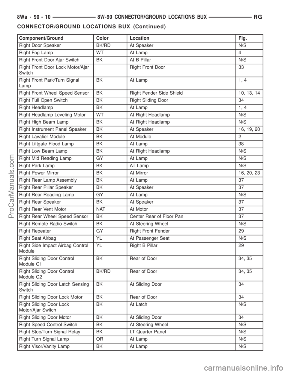
Component/Ground Color Location Fig.
Right Door Speaker BK/RD At Speaker N/S
Right Fog Lamp WT At Lamp 4
Right Front Door Ajar Switch BK At B Pillar N/S
Right Front Door Lock Motor/Ajar
SwitchRight Front Door 33
Right Front Park/Turn Signal
LampBK At Lamp 1, 4
Right Front Wheel Speed Sensor BK Right Fender Side Shield 10, 13, 14
Right Full Open Switch BK Right Sliding Door 34
Right Headlamp BK At Lamp 1, 4
Right Headlamp Leveling Motor WT At Right Headlamp N/S
Right High Beam Lamp BK At Right Headlamp N/S
Right Instrument Panel Speaker BK At Speaker 16, 19, 20
Right Lavalier Module BK At Module 2
Right Liftgate Flood Lamp BK At Lamp 38
Right Low Beam Lamp BK At Right Headlamp N/S
Right Mid Reading Lamp GY At Lamp N/S
Right Park Lamp BK AT Lamp N/S
Right Power Mirror BK At Mirror 16, 20, 23
Right Rear Lamp Assembly BK At Lamp 37
Right Rear Pillar Speaker BK At Speaker 37
Right Rear Reading Lamp GY At Lamp N/S
Right Rear Speaker BK At Speaker 37
Right Rear Vent Motor NAT At Motor 37
Right Rear Wheel Speed Sensor BK Center Rear of Floor Pan 37
Right Remote Radio Switch BK At Steering Wheel N/S
Right Repeater GY Right Front Fender 29
Right Seat Airbag YL At Passenger Seat N/S
Right Side Impact Airbag Control
ModuleYL Right B Pillar 29
Right Sliding Door Control
Module C1BK Rear of Door 34, 35
Right Sliding Door Control
Module C2BK/RD Rear of Door 34, 35
Right Sliding Door Latch Sensing
SwitchBK At Sliding Door 34
Right Sliding Door Lock Motor BK Rear of Door 34
Right Sliding Door Lock
Motor/Ajar SwitchBK At Latch N/S
Right Sliding Door Motor BK At Sliding Door 34
Right Speed Control Switch BK At Steering Wheel N/S
Right Stop/Turn Signal Relay BK LT Quarter Panel N/S
Right Turn Signal Lamp OR At Lamp N/S
Right Visor/Vanity Lamp BK At Lamp N/S
8Wa - 90 - 10 8W-90 CONNECTOR/GROUND LOCATIONS BUXRG
CONNECTOR/GROUND LOCATIONS BUX (Continued)
ProCarManuals.com
Page 1141 of 2321
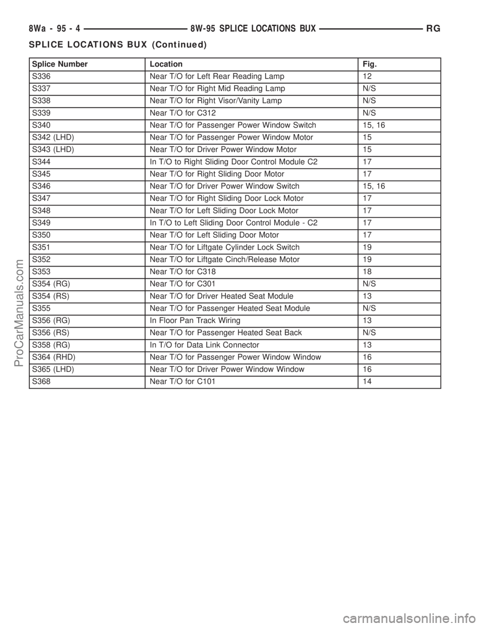
Splice Number Location Fig.
S336 Near T/O for Left Rear Reading Lamp 12
S337 Near T/O for Right Mid Reading Lamp N/S
S338 Near T/O for Right Visor/Vanity Lamp N/S
S339 Near T/O for C312 N/S
S340 Near T/O for Passenger Power Window Switch 15, 16
S342 (LHD) Near T/O for Passenger Power Window Motor 15
S343 (LHD) Near T/O for Driver Power Window Motor 15
S344 In T/O to Right Sliding Door Control Module C2 17
S345 Near T/O for Right Sliding Door Motor 17
S346 Near T/O for Driver Power Window Switch 15, 16
S347 Near T/O for Right Sliding Door Lock Motor 17
S348 Near T/O for Left Sliding Door Lock Motor 17
S349 In T/O to Left Sliding Door Control Module - C2 17
S350 Near T/O for Left Sliding Door Motor 17
S351 Near T/O for Liftgate Cylinder Lock Switch 19
S352 Near T/O for Liftgate Cinch/Release Motor 19
S353 Near T/O for C318 18
S354 (RG) Near T/O for C301 N/S
S354 (RS) Near T/O for Driver Heated Seat Module 13
S355 Near T/O for Passenger Heated Seat Module N/S
S356 (RG) In Floor Pan Track Wiring 13
S356 (RS) Near T/O for Passenger Heated Seat Back N/S
S358 (RG) In T/O for Data Link Connector 13
S364 (RHD) Near T/O for Passenger Power Window Window 16
S365 (LHD) Near T/O for Driver Power Window Window 16
S368 Near T/O for C101 14
8Wa - 95 - 4 8W-95 SPLICE LOCATIONS BUXRG
SPLICE LOCATIONS BUX (Continued)
ProCarManuals.com
Page 1896 of 2321
TIRES/WHEELS
TABLE OF CONTENTS
page page
TIRES/WHEELS
DIAGNOSIS AND TESTING..................1
TIRE AND WHEEL VIBRATION..............1
STANDARD PROCEDURE...................4
TIRE AND WHEEL BALANCE...............4
TIRE AND WHEEL MATCH MOUNTING.......6
TIRE AND WHEEL ROTATION..............6
REMOVAL...............................7
INSTALLATION............................7
TIRES
DESCRIPTION............................8
DIAGNOSIS AND TESTING..................9
TIRE NOISE............................9
TIRE/VEHICLE LEAD.....................9
TIRE WEAR PATTERNS..................11
TREAD WEAR INDICATORS...............11
STANDARD PROCEDURE..................11
TIRE INFLATION PRESSURES.............11
TIRE PRESSURE FOR HIGH SPEED
OPERATION...........................12TIRE LEAK REPAIRING..................12
CLEANING..............................13
WHEELS
DESCRIPTION...........................13
DIAGNOSIS AND TESTING.................13
WHEEL INSPECTION....................13
CLEANING..............................14
SPECIFICATIONS........................14
WHEEL COVER
DESCRIPTION...........................14
REMOVAL..............................14
INSTALLATION...........................14
WHEEL MOUNTING STUDS - FRONT
REMOVAL..............................15
INSTALLATION...........................16
WHEEL MOUNTING STUDS - REAR
REMOVAL..............................16
INSTALLATION...........................17
TIRES/WHEELS
DIAGNOSIS AND TESTING - TIRE AND WHEEL
VIBRATION
Tire and wheel imbalance, runout and force varia-
tion can cause vehicles to exhibit steering wheel
vibration.
VISUAL INSPECTION
Visual inspection of the vehicle is recommended
prior to road testing or performing any other proce-
dure. Raise vehicle on a suitable hoist. Refer to
Hoisting in Lubrication and Maintenance.
Inspect for the following:
²Verify correct (OEM) wheel and tire, as well as
correct wheel weights. Aluminum wheels require
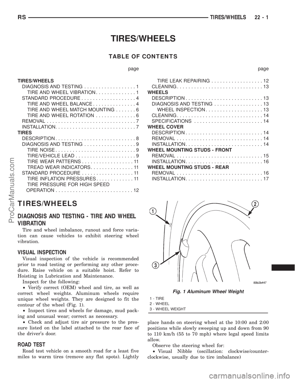
unique wheel weights. They are designed to fit the
contour of the wheel (Fig. 1).
²Inspect tires and wheels for damage, mud pack-
ing and unusual wear; correct as necessary.
²Check and adjust tire air pressure to the pres-
sure listed on the label attached to the rear face of
the driver's door.
ROAD TEST
Road test vehicle on a smooth road for a least five
miles to warm tires (remove any flat spots). Lightlyplace hands on steering wheel at the 10:00 and 2:00
positions while slowly sweeping up and down from 90
to 110 km/h (55 to 70 mph) where legal speed limits
allow.
Observe the steering wheel for:
²Visual Nibble (oscillation: clockwise/counter-
clockwise, usually due to tire imbalance)
Fig. 1 Aluminum Wheel Weight
1 - TIRE
2 - WHEEL
3 - WHEEL WEIGHT
RSTIRES/WHEELS22-1
ProCarManuals.com
Page 1914 of 2321
BODY
TABLE OF CONTENTS
page page
BODY
DESCRIPTION............................1
WARNING...............................2
DIAGNOSIS AND TESTING..................2
WATER LEAKS..........................2
WIND NOISE...........................3
STANDARD PROCEDURE...................4
PLASTIC BODY PANEL REPAIR.............4
HEAT STAKING.........................8
SPECIFICATIONS.........................9
SPECIAL TOOLS........................151DOOR - FRONT.........................152
DOORS - SLIDING.......................162
DECKLID/HATCH/LIFTGATE/TAILGATE.......180
EXTERIOR.............................184
HOOD................................199
INSTRUMENT PANEL....................202
INTERIOR.............................208
PAINT................................220
SEATS................................222
STATIONARY GLASS.....................243
WEATHERSTRIP/SEALS..................248
BODY
DESCRIPTION - LOCK CYLINDERS
Ignition, door, deck lid, and rear hatch lock cylin-
ders are all codable to the key. Lock barrels, tum-
blers, and tumbler springs are available to allow the
technician to change replacement locks cylinders to
match the customer's original key set. See the appro-
priate section in this manual for lock cylinder
removal. See the Moparž catalogue for part numbers
and lock coding procedures.
DESCRIPTION - VEHICLE IDENTIFICATION
Throughout this group, references to the
DaimlerChrysler Corporation vehicle family identifi-
cation code are used when describing a procedure
that is unique to that vehicle. Refer to Introduction
Group of this manual for detailed information on
vehicle identification. If a procedure is common to all
vehicles covered in this manual, no reference will be
made to a vehicle family code.
DESCRIPTION - PUSH-IN FASTENERS
DaimlerChrysler Corporation uses many different
types of push-in fasteners to secure the interior and
exterior trim to the body. Most of these fasteners can
be reused to assemble the trim during various repair
procedures. At times, a push-in fastener cannot be
removed without damaging the fastener or the com-
ponent it is holding. If it is not possible to remove a
fastener without damaging a component or body, cut
or break the fastener and use a new one when
installing the component. Never pry or pound on a
plastic or pressed-board trim component. Using a
suitable fork-type prying device, pry the fastener
from the retaining hole behind the component beingremoved. When installing, verify fastener alignment
with the retaining hole by hand. Push directly on or
over the fastener until it seats. Apply a low-force pull
to the panel to verify that it is secure.
When it is necessary to remove components to ser-
vice another, it should not be necessary to apply
excessive force or bend a component to remove it.
Before damaging a trim component, verify hidden
fasteners or captured edges holding the component in
place.
DESCRIPTION
PAINT
The original equipment finish is a multi-step pro-
cess that involves cleaning, electrodeposition (e-coat),
base coat, and clear coat steps. Additionally, selected
areas of the vehicle may be coated with an anti-chip
finish.
On most vehicles a two-stage paint application
(base coat/clear coat) is used. Color that is applied to
primer is called base coat. The clear coat protects the
base coat from ultraviolet light and provides a dura-
ble high-gloss finish.
STATIONARY GLASS
Windshields are made of two pieces of glass with a
plastic inner layer. Windshields and selected station-
ary glass are structural members of the vehicle. The
windshield glass is bonded to the windshield frame
with urethane adhesive.
Windshields and other stationary glass protect the
occupants from the effects of the elements. Wind-
shields are also used to retain some airbags in posi-
tion during deployment. Urethane bonded glass is
difficult to salvage during removal. The urethane
bonding is difficult to cut or clean from any surface.
RSBODY23-1
ProCarManuals.com