2001 DODGE RAM steering
[x] Cancel search: steeringPage 356 of 2889
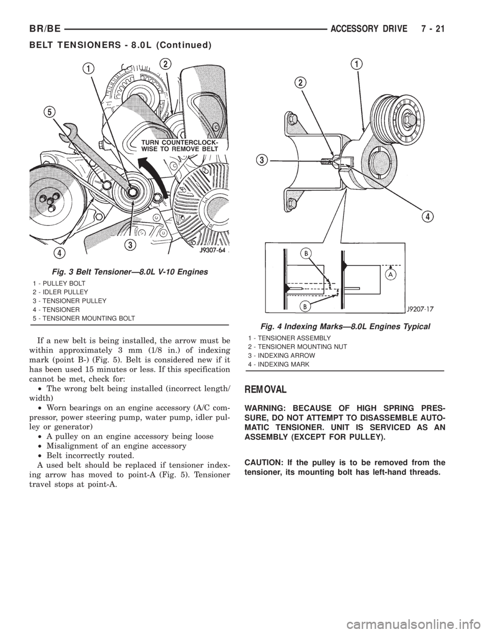
If a new belt is being installed, the arrow must be
within approximately 3 mm (1/8 in.) of indexing
mark (point B-) (Fig. 5). Belt is considered new if it
has been used 15 minutes or less. If this specification
cannot be met, check for:
²The wrong belt being installed (incorrect length/
width)
²Worn bearings on an engine accessory (A/C com-
pressor, power steering pump, water pump, idler pul-
ley or generator)
²A pulley on an engine accessory being loose
²Misalignment of an engine accessory
²Belt incorrectly routed.
A used belt should be replaced if tensioner index-
ing arrow has moved to point-A (Fig. 5). Tensioner
travel stops at point-A.
REMOVAL
WARNING: BECAUSE OF HIGH SPRING PRES-
SURE, DO NOT ATTEMPT TO DISASSEMBLE AUTO-
MATIC TENSIONER. UNIT IS SERVICED AS AN
ASSEMBLY (EXCEPT FOR PULLEY).
CAUTION: If the pulley is to be removed from the
tensioner, its mounting bolt has left-hand threads.
Fig. 3 Belt TensionerÐ8.0L V-10 Engines
1 - PULLEY BOLT
2 - IDLER PULLEY
3 - TENSIONER PULLEY
4 - TENSIONER
5 - TENSIONER MOUNTING BOLT
Fig. 4 Indexing MarksÐ8.0L Engines Typical
1 - TENSIONER ASSEMBLY
2 - TENSIONER MOUNTING NUT
3 - INDEXING ARROW
4 - INDEXING MARK
BR/BEACCESSORY DRIVE 7 - 21
BELT TENSIONERS - 8.0L (Continued)
Page 358 of 2889
BELT TENSIONERS - 5.9L
DIESEL
DESCRIPTION
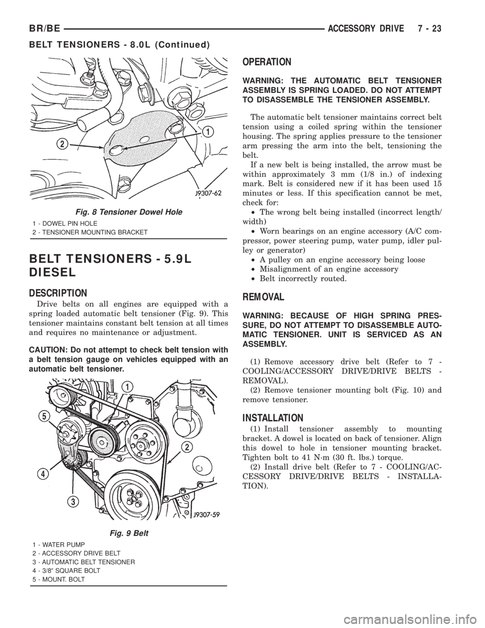
Drive belts on all engines are equipped with a
spring loaded automatic belt tensioner (Fig. 9). This
tensioner maintains constant belt tension at all times
and requires no maintenance or adjustment.
CAUTION: Do not attempt to check belt tension with
a belt tension gauge on vehicles equipped with an
automatic belt tensioner.
OPERATION
WARNING: THE AUTOMATIC BELT TENSIONER
ASSEMBLY IS SPRING LOADED. DO NOT ATTEMPT
TO DISASSEMBLE THE TENSIONER ASSEMBLY.
The automatic belt tensioner maintains correct belt
tension using a coiled spring within the tensioner
housing. The spring applies pressure to the tensioner
arm pressing the arm into the belt, tensioning the
belt.
If a new belt is being installed, the arrow must be
within approximately 3 mm (1/8 in.) of indexing
mark. Belt is considered new if it has been used 15
minutes or less. If this specification cannot be met,
check for:
²The wrong belt being installed (incorrect length/
width)
²Worn bearings on an engine accessory (A/C com-
pressor, power steering pump, water pump, idler pul-
ley or generator)
²A pulley on an engine accessory being loose
²Misalignment of an engine accessory
²Belt incorrectly routed.
REMOVAL
WARNING: BECAUSE OF HIGH SPRING PRES-
SURE, DO NOT ATTEMPT TO DISASSEMBLE AUTO-
MATIC TENSIONER. UNIT IS SERVICED AS AN
ASSEMBLY.
(1) Remove accessory drive belt (Refer to 7 -
COOLING/ACCESSORY DRIVE/DRIVE BELTS -
REMOVAL).
(2) Remove tensioner mounting bolt (Fig. 10) and
remove tensioner.
INSTALLATION
(1) Install tensioner assembly to mounting
bracket. A dowel is located on back of tensioner. Align
this dowel to hole in tensioner mounting bracket.
Tighten bolt to 41 N´m (30 ft. lbs.) torque.
(2) Install drive belt (Refer to 7 - COOLING/AC-
CESSORY DRIVE/DRIVE BELTS - INSTALLA-
TION).
Fig. 8 Tensioner Dowel Hole
1 - DOWEL PIN HOLE
2 - TENSIONER MOUNTING BRACKET
Fig. 9 Belt
1 - WATER PUMP
2 - ACCESSORY DRIVE BELT
3 - AUTOMATIC BELT TENSIONER
4 - 3/89SQUARE BOLT
5 - MOUNT. BOLT
BR/BEACCESSORY DRIVE 7 - 23
BELT TENSIONERS - 8.0L (Continued)
Page 361 of 2889
CONDITION POSSIBLE CAUSES CORRECTION
NOISE
(Objectionable squeal, squeak, or
rumble is heard or felt while drive
belt is in operation)1. Incorrect belt tension 1. Inspect/Replace tensioner if
necessary
2. Bearing noise 2. Locate and repair
3. Belt misalignment 3. Align belt/pulley(s)
4. Belt to pulley mismatch 4. Install correct belt
5. Driven component induced
vibration5. Locate defective driven
component and repair
TENSION SHEETING FABRIC
FAILURE
(Woven fabric on outside,
circumference of belt has cracked or
separated from body of belt)1. Tension sheeting contacting
stationary object1. Correct rubbing condition
2. Excessive heat causing woven
fabric to age2. Replace belt
3. Tension sheeting splice has
fractured3. Replace belt
CORD EDGE FAILURE
(Tensile member exposed at edges
of belt or separated from belt body)1. Incorrect belt tension 1. Inspect/Replace tensioner if
necessary
2. Belt contacting stationary object 2. Replace belt
3. Pulley(s) out of tolerance 3. Replace pulley
4. Insufficient adhesion between
tensile member and rubber matrix4. Replace belt
REMOVAL
NOTE: The belt routing schematics are published
from the latest information available at the time of
publication. If anything differs between these sche-
matics and the Belt Routing Label, use the sche-
matics on Belt Routing Label.This label is located in
the engine compartment.
CAUTION: Do not attempt to check belt tension with
a belt tension gauge on vehicles equipped with an
automatic belt tensioner. Refer to Automatic Belt
Tensioner in this group.
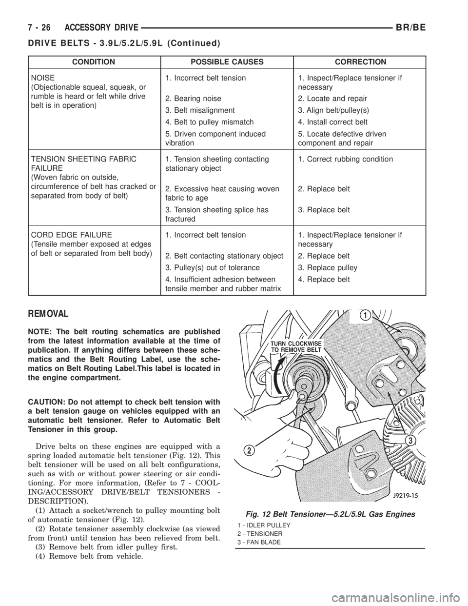
Drive belts on these engines are equipped with a
spring loaded automatic belt tensioner (Fig. 12). This
belt tensioner will be used on all belt configurations,
such as with or without power steering or air condi-
tioning. For more information, (Refer to 7 - COOL-
ING/ACCESSORY DRIVE/BELT TENSIONERS -
DESCRIPTION).
(1) Attach a socket/wrench to pulley mounting bolt
of automatic tensioner (Fig. 12).
(2) Rotate tensioner assembly clockwise (as viewed
from front) until tension has been relieved from belt.
(3) Remove belt from idler pulley first.
(4) Remove belt from vehicle.
Fig. 12 Belt TensionerÐ5.2L/5.9L Gas Engines
1 - IDLER PULLEY
2 - TENSIONER
3 - FAN BLADE
7 - 26 ACCESSORY DRIVEBR/BE
DRIVE BELTS - 3.9L/5.2L/5.9L (Continued)
Page 362 of 2889
INSTALLATION
CAUTION: When installing the accessory drive belt,
the belt must be routed correctly. If not, engine may
overheat due to water pump rotating in wrong
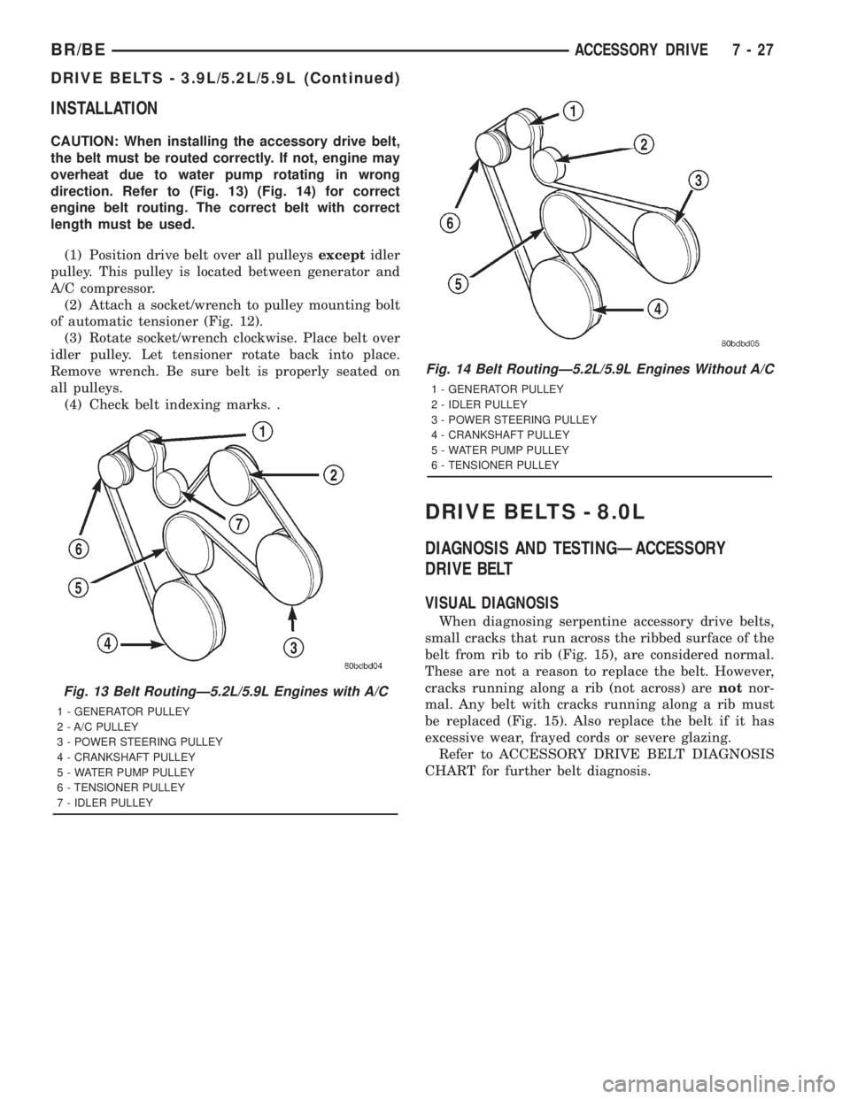
direction. Refer to (Fig. 13) (Fig. 14) for correct
engine belt routing. The correct belt with correct
length must be used.
(1) Position drive belt over all pulleysexceptidler
pulley. This pulley is located between generator and
A/C compressor.
(2) Attach a socket/wrench to pulley mounting bolt
of automatic tensioner (Fig. 12).
(3) Rotate socket/wrench clockwise. Place belt over
idler pulley. Let tensioner rotate back into place.
Remove wrench. Be sure belt is properly seated on
all pulleys.
(4) Check belt indexing marks. .
DRIVE BELTS - 8.0L
DIAGNOSIS AND TESTINGÐACCESSORY
DRIVE BELT
VISUAL DIAGNOSIS
When diagnosing serpentine accessory drive belts,
small cracks that run across the ribbed surface of the
belt from rib to rib (Fig. 15), are considered normal.
These are not a reason to replace the belt. However,
cracks running along a rib (not across) arenotnor-
mal. Any belt with cracks running along a rib must
be replaced (Fig. 15). Also replace the belt if it has
excessive wear, frayed cords or severe glazing.
Refer to ACCESSORY DRIVE BELT DIAGNOSIS
CHART for further belt diagnosis.
Fig. 13 Belt RoutingÐ5.2L/5.9L Engines with A/C
1 - GENERATOR PULLEY
2 - A/C PULLEY
3 - POWER STEERING PULLEY
4 - CRANKSHAFT PULLEY
5 - WATER PUMP PULLEY
6 - TENSIONER PULLEY
7 - IDLER PULLEY
Fig. 14 Belt RoutingÐ5.2L/5.9L Engines Without A/C
1 - GENERATOR PULLEY
2 - IDLER PULLEY
3 - POWER STEERING PULLEY
4 - CRANKSHAFT PULLEY
5 - WATER PUMP PULLEY
6 - TENSIONER PULLEY
BR/BEACCESSORY DRIVE 7 - 27
DRIVE BELTS - 3.9L/5.2L/5.9L (Continued)
Page 365 of 2889
REMOVAL
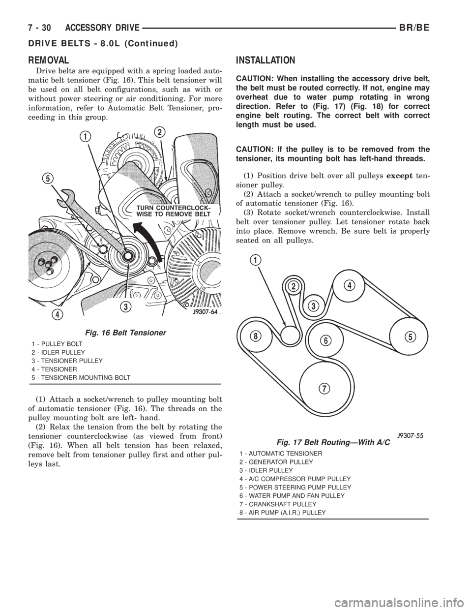
Drive belts are equipped with a spring loaded auto-
matic belt tensioner (Fig. 16). This belt tensioner will
be used on all belt configurations, such as with or
without power steering or air conditioning. For more
information, refer to Automatic Belt Tensioner, pro-
ceeding in this group.
(1) Attach a socket/wrench to pulley mounting bolt
of automatic tensioner (Fig. 16). The threads on the
pulley mounting bolt are left- hand.
(2) Relax the tension from the belt by rotating the
tensioner counterclockwise (as viewed from front)
(Fig. 16). When all belt tension has been relaxed,
remove belt from tensioner pulley first and other pul-
leys last.
INSTALLATION
CAUTION: When installing the accessory drive belt,
the belt must be routed correctly. If not, engine may
overheat due to water pump rotating in wrong
direction. Refer to (Fig. 17) (Fig. 18) for correct
engine belt routing. The correct belt with correct
length must be used.
CAUTION: If the pulley is to be removed from the
tensioner, its mounting bolt has left-hand threads.
(1) Position drive belt over all pulleysexceptten-
sioner pulley.
(2) Attach a socket/wrench to pulley mounting bolt
of automatic tensioner (Fig. 16).
(3) Rotate socket/wrench counterclockwise. Install
belt over tensioner pulley. Let tensioner rotate back
into place. Remove wrench. Be sure belt is properly
seated on all pulleys.
Fig. 16 Belt Tensioner
1 - PULLEY BOLT
2 - IDLER PULLEY
3 - TENSIONER PULLEY
4 - TENSIONER
5 - TENSIONER MOUNTING BOLT
Fig. 17 Belt RoutingÐWith A/C
1 - AUTOMATIC TENSIONER
2 - GENERATOR PULLEY
3 - IDLER PULLEY
4 - A/C COMPRESSOR PUMP PULLEY
5 - POWER STEERING PUMP PULLEY
6 - WATER PUMP AND FAN PULLEY
7 - CRANKSHAFT PULLEY
8 - AIR PUMP (A.I.R.) PULLEY
7 - 30 ACCESSORY DRIVEBR/BE
DRIVE BELTS - 8.0L (Continued)
Page 366 of 2889
DRIVE BELTS - 5.9L DIESEL
DIAGNOSIS AND TESTINGÐACCESSORY
DRIVE BELT
VISUAL DIAGNOSIS
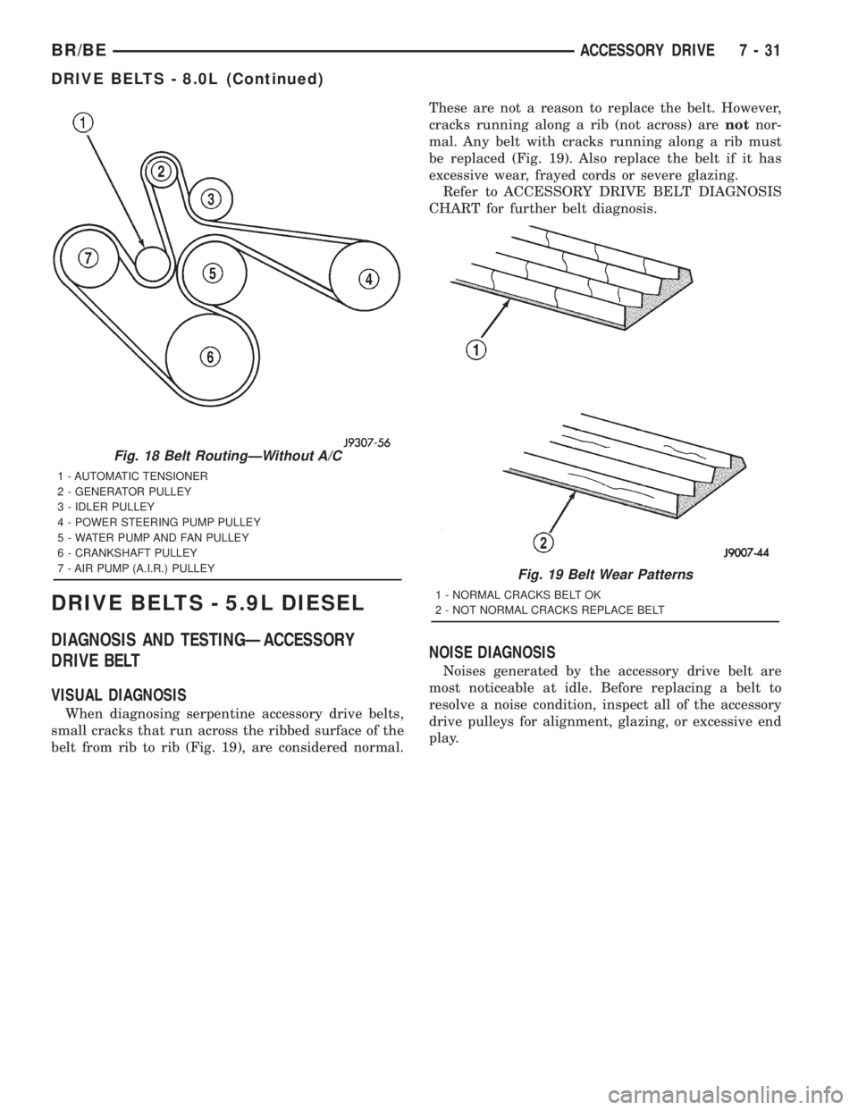
When diagnosing serpentine accessory drive belts,
small cracks that run across the ribbed surface of the
belt from rib to rib (Fig. 19), are considered normal.These are not a reason to replace the belt. However,
cracks running along a rib (not across) arenotnor-
mal. Any belt with cracks running along a rib must
be replaced (Fig. 19). Also replace the belt if it has
excessive wear, frayed cords or severe glazing.
Refer to ACCESSORY DRIVE BELT DIAGNOSIS
CHART for further belt diagnosis.
NOISE DIAGNOSIS
Noises generated by the accessory drive belt are
most noticeable at idle. Before replacing a belt to
resolve a noise condition, inspect all of the accessory
drive pulleys for alignment, glazing, or excessive end
play.
Fig. 18 Belt RoutingÐWithout A/C
1 - AUTOMATIC TENSIONER
2 - GENERATOR PULLEY
3 - IDLER PULLEY
4 - POWER STEERING PUMP PULLEY
5 - WATER PUMP AND FAN PULLEY
6 - CRANKSHAFT PULLEY
7 - AIR PUMP (A.I.R.) PULLEY
Fig. 19 Belt Wear Patterns
1 - NORMAL CRACKS BELT OK
2 - NOT NORMAL CRACKS REPLACE BELT
BR/BEACCESSORY DRIVE 7 - 31
DRIVE BELTS - 8.0L (Continued)
Page 369 of 2889
INSTALLATION
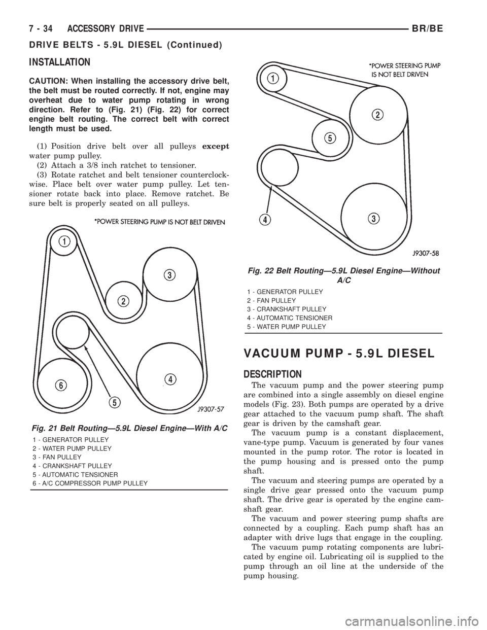
CAUTION: When installing the accessory drive belt,
the belt must be routed correctly. If not, engine may
overheat due to water pump rotating in wrong
direction. Refer to (Fig. 21) (Fig. 22) for correct
engine belt routing. The correct belt with correct
length must be used.
(1) Position drive belt over all pulleysexcept
water pump pulley.
(2) Attach a 3/8 inch ratchet to tensioner.
(3) Rotate ratchet and belt tensioner counterclock-
wise. Place belt over water pump pulley. Let ten-
sioner rotate back into place. Remove ratchet. Be
sure belt is properly seated on all pulleys.
VACUUM PUMP - 5.9L DIESEL
DESCRIPTION
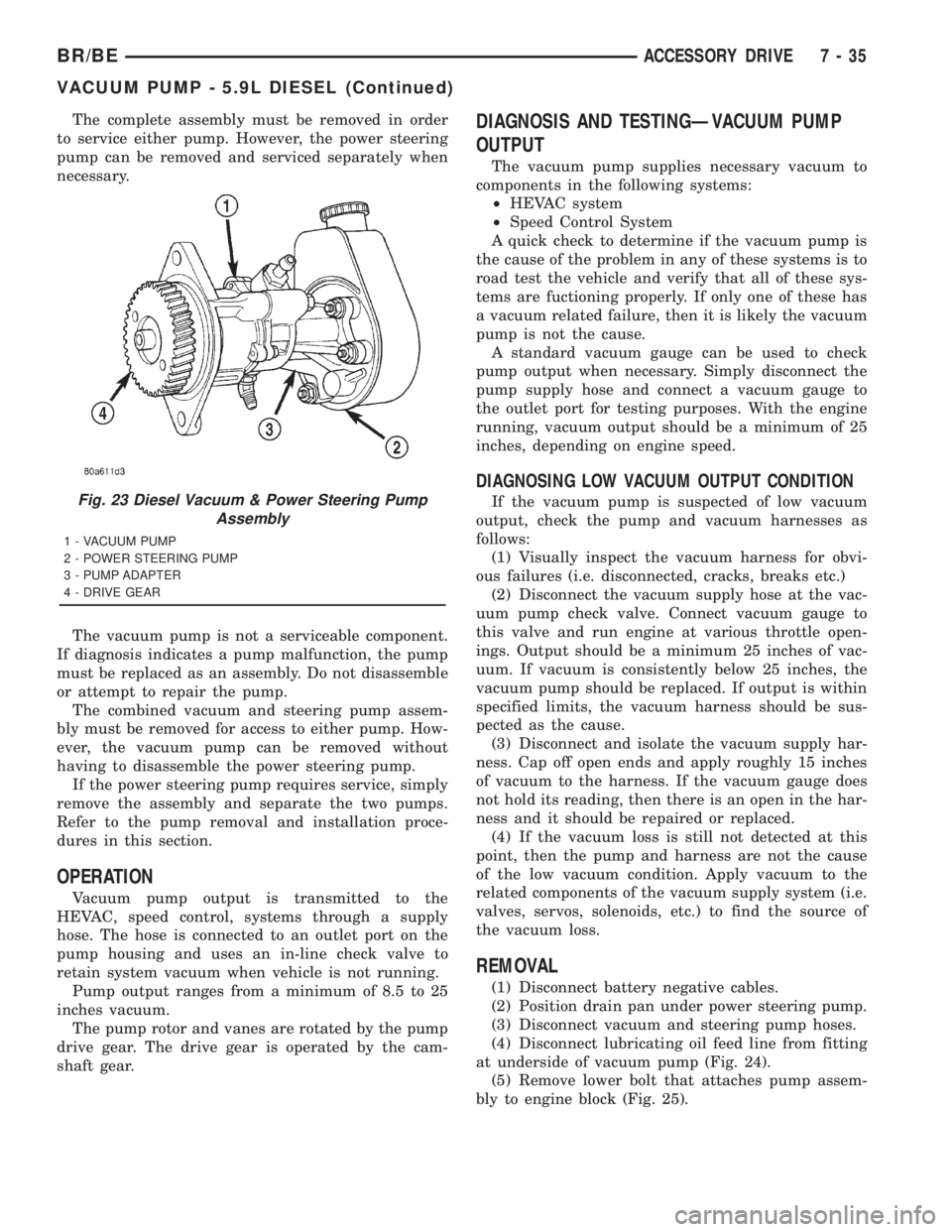
The vacuum pump and the power steering pump
are combined into a single assembly on diesel engine
models (Fig. 23). Both pumps are operated by a drive
gear attached to the vacuum pump shaft. The shaft
gear is driven by the camshaft gear.
The vacuum pump is a constant displacement,
vane-type pump. Vacuum is generated by four vanes
mounted in the pump rotor. The rotor is located in
the pump housing and is pressed onto the pump
shaft.
The vacuum and steering pumps are operated by a
single drive gear pressed onto the vacuum pump
shaft. The drive gear is operated by the engine cam-
shaft gear.
The vacuum and power steering pump shafts are
connected by a coupling. Each pump shaft has an
adapter with drive lugs that engage in the coupling.
The vacuum pump rotating components are lubri-
cated by engine oil. Lubricating oil is supplied to the
pump through an oil line at the underside of the
pump housing.
Fig. 21 Belt RoutingÐ5.9L Diesel EngineÐWith A/C
1 - GENERATOR PULLEY
2 - WATER PUMP PULLEY
3 - FAN PULLEY
4 - CRANKSHAFT PULLEY
5 - AUTOMATIC TENSIONER
6 - A/C COMPRESSOR PUMP PULLEY
Fig. 22 Belt RoutingÐ5.9L Diesel EngineÐWithout
A/C
1 - GENERATOR PULLEY
2 - FAN PULLEY
3 - CRANKSHAFT PULLEY
4 - AUTOMATIC TENSIONER
5 - WATER PUMP PULLEY
7 - 34 ACCESSORY DRIVEBR/BE
DRIVE BELTS - 5.9L DIESEL (Continued)
Page 370 of 2889
The complete assembly must be removed in order
to service either pump. However, the power steering
pump can be removed and serviced separately when
necessary.
The vacuum pump is not a serviceable component.
If diagnosis indicates a pump malfunction, the pump
must be replaced as an assembly. Do not disassemble
or attempt to repair the pump.
The combined vacuum and steering pump assem-
bly must be removed for access to either pump. How-
ever, the vacuum pump can be removed without
having to disassemble the power steering pump.
If the power steering pump requires service, simply
remove the assembly and separate the two pumps.
Refer to the pump removal and installation proce-
dures in this section.
OPERATION
Vacuum pump output is transmitted to the
HEVAC, speed control, systems through a supply
hose. The hose is connected to an outlet port on the
pump housing and uses an in-line check valve to
retain system vacuum when vehicle is not running.
Pump output ranges from a minimum of 8.5 to 25
inches vacuum.
The pump rotor and vanes are rotated by the pump
drive gear. The drive gear is operated by the cam-
shaft gear.
DIAGNOSIS AND TESTINGÐVACUUM PUMP
OUTPUT
The vacuum pump supplies necessary vacuum to
components in the following systems:
²HEVAC system
²Speed Control System
A quick check to determine if the vacuum pump is
the cause of the problem in any of these systems is to
road test the vehicle and verify that all of these sys-
tems are fuctioning properly. If only one of these has
a vacuum related failure, then it is likely the vacuum
pump is not the cause.
A standard vacuum gauge can be used to check
pump output when necessary. Simply disconnect the
pump supply hose and connect a vacuum gauge to
the outlet port for testing purposes. With the engine
running, vacuum output should be a minimum of 25
inches, depending on engine speed.
DIAGNOSING LOW VACUUM OUTPUT CONDITION
If the vacuum pump is suspected of low vacuum
output, check the pump and vacuum harnesses as
follows:
(1) Visually inspect the vacuum harness for obvi-
ous failures (i.e. disconnected, cracks, breaks etc.)
(2) Disconnect the vacuum supply hose at the vac-
uum pump check valve. Connect vacuum gauge to
this valve and run engine at various throttle open-
ings. Output should be a minimum 25 inches of vac-
uum. If vacuum is consistently below 25 inches, the
vacuum pump should be replaced. If output is within
specified limits, the vacuum harness should be sus-
pected as the cause.
(3) Disconnect and isolate the vacuum supply har-
ness. Cap off open ends and apply roughly 15 inches
of vacuum to the harness. If the vacuum gauge does
not hold its reading, then there is an open in the har-
ness and it should be repaired or replaced.
(4) If the vacuum loss is still not detected at this
point, then the pump and harness are not the cause
of the low vacuum condition. Apply vacuum to the
related components of the vacuum supply system (i.e.
valves, servos, solenoids, etc.) to find the source of
the vacuum loss.
REMOVAL
(1) Disconnect battery negative cables.
(2) Position drain pan under power steering pump.
(3) Disconnect vacuum and steering pump hoses.
(4) Disconnect lubricating oil feed line from fitting
at underside of vacuum pump (Fig. 24).
(5) Remove lower bolt that attaches pump assem-
bly to engine block (Fig. 25).
Fig. 23 Diesel Vacuum & Power Steering Pump
Assembly
1 - VACUUM PUMP
2 - POWER STEERING PUMP
3 - PUMP ADAPTER
4 - DRIVE GEAR
BR/BEACCESSORY DRIVE 7 - 35
VACUUM PUMP - 5.9L DIESEL (Continued)