2001 DODGE RAM wheel
[x] Cancel search: wheelPage 56 of 2889

(3) Position the indicator plunger against the
upper ball stud boss of the steering knuckle.
(4) Grasp the top of the tire and apply force in and
out. Look for movement at the ball joint between the
upper suspension arm and steering knuckle.
(5) If lateral movement is greater than 0.8 mm
(0.030 in.), replace the suspension arm.
UPPER CONTROL ARM
REMOVAL
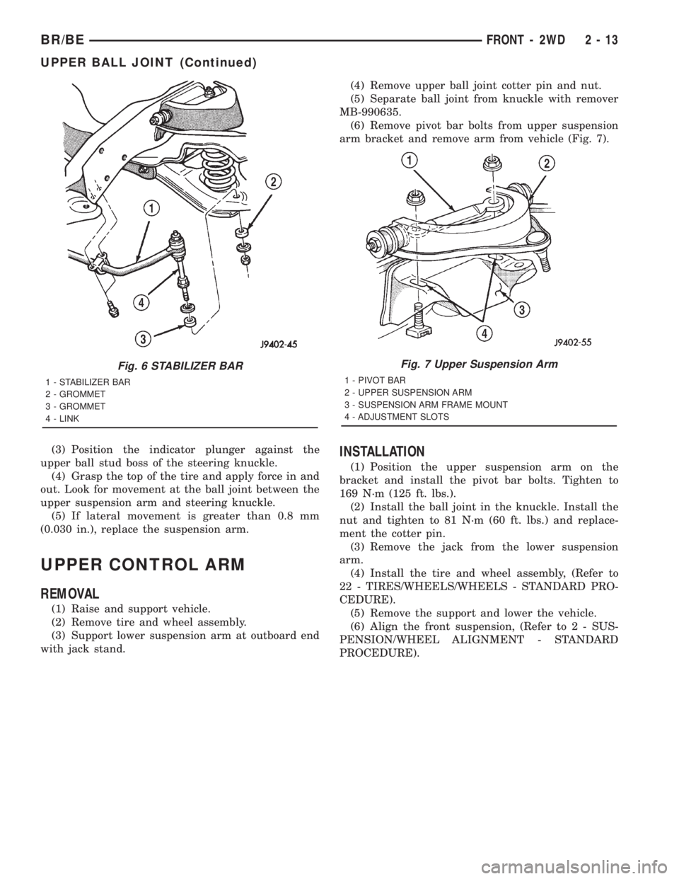
(1) Raise and support vehicle.
(2) Remove tire and wheel assembly.
(3) Support lower suspension arm at outboard end
with jack stand.(4) Remove upper ball joint cotter pin and nut.
(5) Separate ball joint from knuckle with remover
MB-990635.
(6) Remove pivot bar bolts from upper suspension
arm bracket and remove arm from vehicle (Fig. 7).
INSTALLATION
(1) Position the upper suspension arm on the
bracket and install the pivot bar bolts. Tighten to
169 N´m (125 ft. lbs.).
(2) Install the ball joint in the knuckle. Install the
nut and tighten to 81 N´m (60 ft. lbs.) and replace-
ment the cotter pin.
(3) Remove the jack from the lower suspension
arm.
(4) Install the tire and wheel assembly, (Refer to
22 - TIRES/WHEELS/WHEELS - STANDARD PRO-
CEDURE).
(5) Remove the support and lower the vehicle.
(6) Align the front suspension, (Refer to 2 - SUS-
PENSION/WHEEL ALIGNMENT - STANDARD
PROCEDURE).
Fig. 6 STABILIZER BAR
1 - STABILIZER BAR
2 - GROMMET
3 - GROMMET
4 - LINK
Fig. 7 Upper Suspension Arm
1 - PIVOT BAR
2 - UPPER SUSPENSION ARM
3 - SUSPENSION ARM FRAME MOUNT
4 - ADJUSTMENT SLOTS
BR/BEFRONT - 2WD 2 - 13
UPPER BALL JOINT (Continued)
Page 57 of 2889

FRONT - 4WD
TABLE OF CONTENTS
page page
FRONT - 4WD
DESCRIPTION...........................14
SPECIFICATIONS........................15
SPECIAL TOOLS.........................16
HUB / BEARING
REMOVAL..............................16
INSTALLATION...........................18
KNUCKLE
DESCRIPTION...........................20
OPERATION.............................20
REMOVAL..............................20
INSTALLATION...........................20
LOWER CONTROL ARM
REMOVAL..............................20
INSTALLATION...........................20
SHOCK
DESCRIPTION...........................21
OPERATION.............................21
DIAGNOSIS AND TESTING.................21
SHOCK..............................21
REMOVAL..............................21
INSTALLATION...........................21
SPRING
DESCRIPTION...........................22OPERATION.............................22
REMOVAL..............................22
INSTALLATION...........................22
STABILIZER BAR
DESCRIPTION...........................22
OPERATION.............................22
REMOVAL..............................22
INSTALLATION...........................23
TRACK BAR
DESCRIPTION...........................23
OPERATION.............................23
DIAGNOSIS AND TESTING.................23
TRACK BAR...........................23
REMOVAL..............................23
INSTALLATION...........................23
UPPER CONTROL ARM
REMOVAL..............................23
INSTALLATION...........................24
LOWER BALL JOINT
REMOVAL..............................24
INSTALLATION...........................25
UPPER BALL JOINT
REMOVAL..............................25
INSTALLATION...........................25
FRONT - 4WD
DESCRIPTION
The link/coil suspension allows each wheel to adapt
to different road surfaces. The suspension is com-
prised of (Fig. 1) :
²Shock absorbers
²Coil springs
²Upper and lower suspension arms
²Stabilizer bar
²Track bar
²Steering Knuckles
²Hub/Bearing
²Ball Joints
²Jounce Bumpers
CAUTION: Components attached with a nut and cot-
ter pin must be torqued to specification. Then if the
slot in the nut does not line up with the cotter pin
hole, tighten nut until it is aligned. Never loosen the
nut to align the cotter pin hole.CAUTION: Suspension components with rubber
bushings (except stabilizer bar) should be tightened
with the vehicle at normal height. It is important to
have the springs supporting the weight of the vehi-
cle when the fasteners are torqued. If springs are
not at their normal ride position, vehicle ride com-
fort could be affected and premature bushing wear
may occur.
DESCRIPTION
The upper and lower suspension arms use bush-
ings to isolate road noise. The suspension arms are
bolted to the frame and axle through the rubber
bushings. The lower suspension arm uses cam bolts
at the axle to allow for caster and pinion angle
adjustment.
2 - 14 FRONT - 4WDBR/BE
Page 59 of 2889

SPECIAL TOOLS
LINK/COIL SUSPENSION
HUB / BEARING
REMOVAL - 2500/3500
(1) Raise and support the vehicle.
(2) Remove the wheel and tire assembly.
(3) Remove the hub extension mounting nuts and
remove the extension from the rotor if equipped (Fig.
2).(4) Remove the brake caliper, (Refer to 5 -
BRAKES/HYDRAULIC/MECHANICAL/DISC
BRAKE CALIPERS - REMOVAL).
(5) Remove the cotter pin and the hub nut from
the axle shaft (Fig. 3).
(6) Disconnect the ABS wheel speed sensor wire
from under the hood. Remove the sensor wire from
the frame and steering knuckle if equipped.
(7) Back off the hub/bearing mounting bolts 1/4
inch each (Fig. 4). Then tap the bolts with a hammer
to loosen the hub/bearing from the steering knuckle.
(8) Remove the hub/bearing mounting bolts and
remove the hub/bearing.
(9) Remove the rotor assembly (Fig. 5), brake
shield and spacer from the steering knuckle.
(10) Press out the wheel studs/hub extension studs
and separate the rotor from the hub (Fig. 6).
Puller C-3894±A
Remover, Wheel Stud C-4150A
Fig. 2 Hub Extension
1 - HUB EXTENSION
2 - HUB
Fig. 3 Hub Nut Cotter Pin
1 - HUB NUT
2 - COTTER PIN
Fig. 4 Hub/Bearing Mounting Bolts
1 - SOCKET AND EXTENSION
2 - ROTOR AND HUB
3 - STEERING KNUCKLE
2 - 16 FRONT - 4WDBR/BE
FRONT - 4WD (Continued)
Page 60 of 2889

(11) Remove the wheel speed sensor (Fig. 7) from
the hub bearing if equipped.
REMOVAL - 1500
(1) Raise and support the vehicle.
(2) Remove the wheel and tire assembly.
(3) Remove the cotter pin and axle hub nut.
(4) Remove the brake caliper with adapter and
rotor, (Refer to 5 - BRAKES/HYDRAULIC/MECHAN-
ICAL/DISC BRAKE CALIPERS - REMOVAL).
(5) Remove the ABS sensor if equipped, (Refer to 5
- BRAKES/ELECTRICAL/FRONT WHEEL SPEED
SENSOR - REMOVAL).(6) Back off the hub/bearing mounting bolts 1/4
inch each (Fig. 8). Then tap the bolts with a hammer
to loosen the hub/bearing from the steering knuckle.
(7) Remove the hub/bearing mounting bolts and
remove the hub/bearing.
(8) Remove the brake shield from the steering
knuckle.
Fig. 5 Rotor Hub/Bearing Assembly
1 - ROTOR AND HUB
2 - UNIT BEARING ASSEMBLY
3 - SEAL
Fig. 6 Rotor And Hub/Bearing
1 - HUB BEARING
2 - ROTOR
Fig. 7 Wheel Speed Sensor
1 - HUB BEARING
2 - WHEEL SPEED SENSOR
Fig. 8 Hub/Bearing Mounting Bolts
1 - BRAKE SHIELD
2 - AXLE YOKE
3 - KNUCKLE
BR/BEFRONT - 4WD 2 - 17
HUB / BEARING (Continued)
Page 61 of 2889

INSTALLATION - 2500/3500
(1) Install the wheel speed sensor in the hub bear-
ing if equipped.
(2) Position the rotor on the hub/bearing.
(3) Press the wheel studs/hub extension studs
through the back side of the rotor and through the
hub bearing flange (Fig. 9).
(4) Apply a liberal quantity of anti-seize compound
to the splines of the front drive shaft.
(5) Insert the two rearmost, top and bottom rotor
hub bolts in the steering knuckle. Insert the bolts
through the back side of the knuckle so they extend
out the front face as shown.
(6) Position the hub spacer (Fig. 10) and brake
shield (Fig. 11) on bolts just installed in knuckle.
NOTE: If the vehicle is equipped with a wheel speed
sensor the brake shield must be positioned on the
hub bearing (Fig. 12).
(7) Align the rotor hub with the drive shaft and
start the shaft into the rotor hub splines.
NOTE: Position wheel speed sensor wire at the top
of the knuckle if equipped.
(8) Align the bolt holes in the hub bearing flange
with the bolts installed in the knuckle. Then threadthe bolts into the bearing flange far enough to hold
the assembly in place.
(9) Install the remaining bolts. Tighten the hub/
bearing bolts to 166 N´m (122 ft. labs.
(10) Install the washer and hub nut and tighten to
245 N´m (180 ft. lbs.).
Fig. 9 Rotor, Hub/Bearing And Stud
1 - HUB BEARING
2 - ROTOR
3 - STUD
Fig. 10 Hub Spacer
1 - ROTOR HUB BOLTS
2 - HUB SPACER (POSITION FLAT TO REAR)
3 - APPLY ANTI-SEIZE COMPOUND TO SPLINES
Fig. 11 Brake Shield
1 - BRAKE SHIELD
2 - HUB BEARING BOLTS
3 - STEERING KNUCKLE
2 - 18 FRONT - 4WDBR/BE
HUB / BEARING (Continued)
Page 62 of 2889

(11) Install a new cotter pin in the hub nut.
Tighten the nut as needed to align the cotter pin hole
in the shaft with the opening in nut.
(12) Install the brake caliper, (Refer to 5 -
BRAKES/HYDRAULIC/MECHANICAL/DISC
BRAKE CALIPERS - INSTALLATION).
(13) Install the sensor wire to the steering knuckle
and frame and if equipped. Connect the wheel speed
sensor wire under the hood.
(14) Install the wheel and tire assemblies, (Refer
to 22 - TIRES/WHEELS/WHEELS - STANDARD
PROCEDURE).
(15) Remove the support and lower the vehicle.
(16) Apply the brakes several times to seat the
brake shoes and caliper piston. Do not move the vehi-
cle until a firm brake pedal is obtained.
INSTALLATION - 1500
(1) Apply a liberal quantity of anti-seize compound
to splines of the front drive shaft.
(2) Insert the bolts (Fig. 13) through back side of
the steering knuckle.
(3) Position the brake shield (Fig. 14) on bolts just
installed in the knuckle.
(4) Align the hub with the drive shaft and start
the shaft into the hub splines.
(5) Align the bolt holes in the hub bearing flange
with bolts installed in the knuckle. Then thread bolts
into the bearing flange.
(6) Tighten the hub bearing bolts to 166 N´m (122
ft. lbs.).
(7) Install the washer and axle hub nut and
tighten to 245 N´m (180 ft. lbs.).
Fig. 12 Brake Shield With Wheel Speed Sensor
1 - WHEEL SPEED SENSOR
2 - HUB BEARING
3 - SHIELD
Fig. 13 Hub Bearing Mounting Bolts
1 - KNUCKLE
2 - AXLE SPLINE
3 - HUB BEARING BOLTS
Fig. 14 Brake Shield
1 - KNUCKLE
2 - BRAKE SHIELD
3 - HUB BEARING BOLTS
BR/BEFRONT - 4WD 2 - 19
HUB / BEARING (Continued)
Page 63 of 2889

(8) Install a new cotter pin in hub nut. Tighten the
nut as needed to align cotter pin hole in shaft with
the opening in the nut.
(9) Install the rotor, brake caliper with adapter,
(Refer to 5 - BRAKES/HYDRAULIC/MECHANICAL/
DISC BRAKE CALIPERS - INSTALLATION).
(10) Install the ABS wheel speed sensor if
equipped, (Refer to 5 - BRAKES/ELECTRICAL/
FRONT WHEEL SPEED SENSOR - INSTALLA-
TION).
(11) Install the wheel and tire assemblies, (Refer
to 22 - TIRES/WHEELS/WHEELS - STANDARD
PROCEDURE).
(12) Remove the support and lower the vehicle.
(13) Apply the brakes several times to seat the
brake shoes and the caliper piston. Do not move the
vehicle until a firm brake pedal is obtained.
KNUCKLE
DESCRIPTION
The knuckles are a single casting with legs
machined for the upper and lower ball joints. The
knuckles also has machined mounting locations for
the front brake calipers adapters and hub bearing
assembly.
OPERATION
The steering knuckles pivots between the upper
and lower ball joints. The steering linkage is
attached to the knuckles controls vehicle steering.
REMOVAL
(1) Remove hub bearing and axle shaft.
(2) Remove tie-rod or drag link end from the steer-
ing knuckle arm.
(3) Remove the ABS sensor wire and bracket from
knuckle.
(4) Remove the cotter pin from the upper ball stud
nut. Remove the upper and lower ball stud nuts.
(5) Strike the steering knuckle with a brass ham-
mer to loosen. Remove knuckle from axle tube yokes.
REMOVAL
(1) Remove hub bearing and axle shaft.
(2) Remove tie-rod or drag link end from the steer-
ing knuckle arm.
(3) Remove the ABS sensor wire and bracket from
knuckle. Refer to Brakes, for proper procedures.
(4) Remove the cotter pin from the upper ball stud
nut. Remove the upper and lower ball stud nuts.
(5) Strike the steering knuckle with a brass ham-
mer to loosen.
(6) Remove knuckle from axle tube yokes.
INSTALLATION
(1) Position the steering knuckle on the ball studs.
(2) Install and tighten lower ball stud nut to 108
N´m (80 ft. lbs.) torque. Advance nut to next slot to
line up hole and install new cotter pin.
(3) Install and tighten upper ball stud nut to 101
N´m (75 ft. lbs.) torque. Advance nut to next slot to
line up hole and install new cotter pin.
(4) Install the hub bearing and axle shaft.
(5) Install tie-rod or drag link end onto the steer-
ing knuckle arm.
(6) Install the ABS sensor wire and bracket to the
knuckle. Refer to Brakes, for proper procedures.
INSTALLATION
(1) Position the steering knuckle on the ball studs.
(2) Install and tighten lower ball stud nut to 47
N´m (35 ft. lbs.) torque. Do not install cotter pin at
this time.
(3) Install and tighten upper ball stud nut to 94
N´m (70 ft. lbs.) torque. Advance nut to next slot to
line up hole and install new cotter pin.
(4) Retorque lower ball stud nut to 190±217 N´m
(140±160 ft. lbs.) torque. Advance nut to next slot to
line up hole and install new cotter pin.
(5) Install the hub bearing and axle shaft.
(6) Install tie-rod or drag link end onto the steer-
ing knuckle arm.
(7) Install the ABS sensor wire and bracket to the
knuckle. Refer to Brakes, for proper procedure.
LOWER CONTROL ARM
REMOVAL
(1) Raise and support the vehicle.
(2) Paint or scribe alignment marks on the cam
adjusters and suspension arm for installation refer-
ence (Fig. 15).
(3) Remove the lower suspension arm nut, cam
and cam bolt from the axle.
(4) Remove the nut and bolt from the frame rail
bracket and remove the lower suspension arm (Fig.
22).
INSTALLATION
(1) Position the lower suspension arm at the axle
bracket and frame rail bracket.
(2) Install the rear bolt and finger tighten the nut.
(3) Install the cam bolt, cam and nut in the axle
and align the reference marks.
(4) Remove support and lower the vehicle.
(5) Tighten cam nut at the axle bracket to 190
N´m (140 ft. lbs.). Tighten rear nut at the frame
bracket to 190 N´m (140 ft. lbs.).
2 - 20 FRONT - 4WDBR/BE
HUB / BEARING (Continued)
Page 66 of 2889

INSTALLATION
(1) Position the stabilizer bar on the frame rail
and install the clamps and bolts. Ensure the bar is
centered with equal spacing on both sides.
(2) Tighten the clamp bolts to 54 N´m (40 ft. lbs.).
(3) Install links to the axle bracket and tighten
nut to 47 N´m (35 ft. lbs.).
(4) Install links, retainers, grommets and nuts to
the stabilizer bar. Hold the link shaft with a wrench
and tighten the nuts to 37 N´m (27 ft. lbs.).
(5) Remove the supports and lower the vehicle.
TRACK BAR
DESCRIPTION
The bar is attached to a frame rail bracket with a
ball stud and is isolated with a bushing at the axle
bracket.
OPERATION
The track bar is used to control front axle side-to-
side movement.
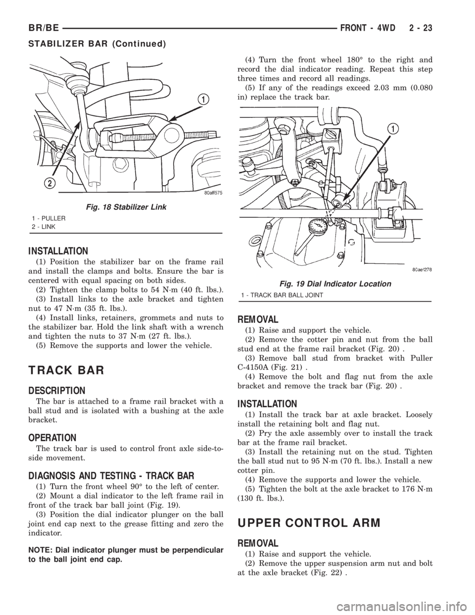
DIAGNOSIS AND TESTING - TRACK BAR
(1) Turn the front wheel 90É to the left of center.
(2) Mount a dial indicator to the left frame rail in
front of the track bar ball joint (Fig. 19).
(3) Position the dial indicator plunger on the ball
joint end cap next to the grease fitting and zero the
indicator.
NOTE: Dial indicator plunger must be perpendicular
to the ball joint end cap.(4) Turn the front wheel 180É to the right and
record the dial indicator reading. Repeat this step
three times and record all readings.
(5) If any of the readings exceed 2.03 mm (0.080
in) replace the track bar.
REMOVAL
(1) Raise and support the vehicle.
(2) Remove the cotter pin and nut from the ball
stud end at the frame rail bracket (Fig. 20) .
(3) Remove ball stud from bracket with Puller
C-4150A (Fig. 21) .
(4) Remove the bolt and flag nut from the axle
bracket and remove the track bar (Fig. 20) .
INSTALLATION
(1) Install the track bar at axle bracket. Loosely
install the retaining bolt and flag nut.
(2) Pry the axle assembly over to install the track
bar at the frame rail bracket.
(3) Install the retaining nut on the stud. Tighten
the ball stud nut to 95 N´m (70 ft. lbs.). Install a new
cotter pin.
(4) Remove the supports and lower the vehicle.
(5) Tighten the bolt at the axle bracket to 176 N´m
(130 ft. lbs.).
UPPER CONTROL ARM
REMOVAL
(1) Raise and support the vehicle.
(2) Remove the upper suspension arm nut and bolt
at the axle bracket (Fig. 22) .
Fig. 18 Stabilizer Link
1 - PULLER
2 - LINK
Fig. 19 Dial Indicator Location
1 - TRACK BAR BALL JOINT
BR/BEFRONT - 4WD 2 - 23
STABILIZER BAR (Continued)