2001 DODGE RAM service
[x] Cancel search: servicePage 118 of 2889
FRONT AXLE - 248FBI
TABLE OF CONTENTS
page page
FRONT AXLE - 248FBI
DESCRIPTION...........................45
OPERATION.............................45
DIAGNOSIS AND TESTING.................46
AXLE................................46
REMOVAL..............................50
INSTALLATION...........................50
ADJUSTMENTS..........................50
SPECIFICATIONS........................58
SPECIAL TOOLS.........................58
AXLE SHAFTS
REMOVAL..............................60
INSTALLATION...........................60
AXLE SHAFTS - INTERMEDIATE
REMOVAL..............................60
INSTALLATION...........................61
AXLE SHAFT SEALS
REMOVAL..............................61
INSTALLATION...........................61
AXLE VACUUM MOTOR
DESCRIPTION...........................62
OPERATION.............................62
DIAGNOSIS AND TESTING.................63VACUUM MOTOR.......................63
REMOVAL..............................65
DISASSEMBLY...........................65
ASSEMBLY.............................65
INSTALLATION...........................65
SINGLE CARDAN UNIVERSAL JOINTS
REMOVAL..............................65
INSTALLATION...........................66
PINION SEAL
REMOVAL..............................66
INSTALLATION...........................66
DIFFERENTIAL
REMOVAL..............................68
DISASSEMBLY...........................68
ASSEMBLY.............................69
INSTALLATION...........................69
DIFFERENTIAL CASE BEARINGS
REMOVAL..............................71
INSTALLATION...........................71
PINION GEAR/RING GEAR
REMOVAL..............................72
INSTALLATION...........................74
FRONT AXLE - 248FBI
DESCRIPTION
The housing for the 248 Front Beam-design Iron
(FBI) axle consists of an iron center casting with
tubes on each side. The tubes are pressed into and
welded to the differential housing.
The integral type housing, hypoid gear design has
the centerline of the pinion set below the centerline
of the ring gear.
The axle has a vent used to relieve internal pres-
sure caused by lubricant vaporization and internal
expansion.
The axles are equipped with semi-floating axle
shafts, meaning that loads are supported by the hub
bearings. The axle shafts are retained by nuts at the
hub bearings. The hub bearings are bolted to the
steering knuckle at the outboard end of the axle tube
yoke. The hub bearings are serviced as an assembly.
The axles are equipped with ABS brake sensors.
The sensors are attached to the knuckle assemblies
and the tone rings are pressed onto the axle shaft.
Use care when removing axle shafts as NOT to
damage the tone wheel or the sensor.The stamped steel cover provides a means for
inspection and servicing the differential.
The 248 FBI axle have the assembly part number
and gear ratio listed on a tag. The tag is attached to
the housing cover by one of the cover bolts. Build
date identification codes are stamped on the cover
side of a axle tube.
The differential case is a one-piece design. The dif-
ferential pinion mate shaft is retained with a roll
pin. Differential bearing preload and ring gear back-
lash is adjusted by the use of shims. The shims are
located between the differential bearing cones and
case. Pinion bearing preload is set and maintained by
the use of a collapsible spacer.
The axle differential covers can be used for identi-
fication of the axle (Fig. 1). A tag is also attached to
the cover.
OPERATION
The axle receives power from the transfer case
through the front propeller shaft. The front propeller
shaft is connected to the pinion gear which rotates
the differential through the gear mesh with the ring
gear bolted to the differential case. The engine power
is transmitted to the axle shafts through the pinion
BR/BEFRONT AXLE - 248FBI 3 - 45
Page 121 of 2889
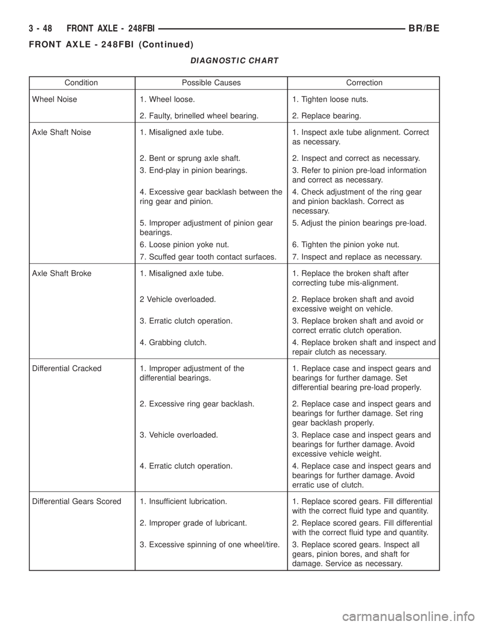
DIAGNOSTIC CHART
Condition Possible Causes Correction
Wheel Noise 1. Wheel loose. 1. Tighten loose nuts.
2. Faulty, brinelled wheel bearing. 2. Replace bearing.
Axle Shaft Noise 1. Misaligned axle tube. 1. Inspect axle tube alignment. Correct
as necessary.
2. Bent or sprung axle shaft. 2. Inspect and correct as necessary.
3. End-play in pinion bearings. 3. Refer to pinion pre-load information
and correct as necessary.
4. Excessive gear backlash between the
ring gear and pinion.4. Check adjustment of the ring gear
and pinion backlash. Correct as
necessary.
5. Improper adjustment of pinion gear
bearings.5. Adjust the pinion bearings pre-load.
6. Loose pinion yoke nut. 6. Tighten the pinion yoke nut.
7. Scuffed gear tooth contact surfaces. 7. Inspect and replace as necessary.
Axle Shaft Broke 1. Misaligned axle tube. 1. Replace the broken shaft after
correcting tube mis-alignment.
2 Vehicle overloaded. 2. Replace broken shaft and avoid
excessive weight on vehicle.
3. Erratic clutch operation. 3. Replace broken shaft and avoid or
correct erratic clutch operation.
4. Grabbing clutch. 4. Replace broken shaft and inspect and
repair clutch as necessary.
Differential Cracked 1. Improper adjustment of the
differential bearings.1. Replace case and inspect gears and
bearings for further damage. Set
differential bearing pre-load properly.
2. Excessive ring gear backlash. 2. Replace case and inspect gears and
bearings for further damage. Set ring
gear backlash properly.
3. Vehicle overloaded. 3. Replace case and inspect gears and
bearings for further damage. Avoid
excessive vehicle weight.
4. Erratic clutch operation. 4. Replace case and inspect gears and
bearings for further damage. Avoid
erratic use of clutch.
Differential Gears Scored 1. Insufficient lubrication. 1. Replace scored gears. Fill differential
with the correct fluid type and quantity.
2. Improper grade of lubricant. 2. Replace scored gears. Fill differential
with the correct fluid type and quantity.
3. Excessive spinning of one wheel/tire. 3. Replace scored gears. Inspect all
gears, pinion bores, and shaft for
damage. Service as necessary.
3 - 48 FRONT AXLE - 248FBIBR/BE
FRONT AXLE - 248FBI (Continued)
Page 125 of 2889
NOTE: Arbor Discs 6732 has different step diame-
ters to fit other axles. Choose proper step for axle
being serviced.(5) Install differential bearing caps on arbor discs
and snug the bearing cap bolts. Then cross tighten
cap bolts to 108 N´m (80 ft. lbs.).
(6) Assemble Dial Indicator C-3339 into Scooter
Block D-115-2 and secure set screw.
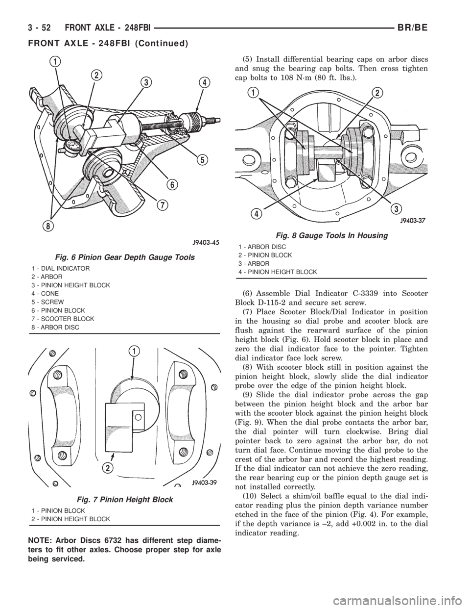
(7) Place Scooter Block/Dial Indicator in position
in the housing so dial probe and scooter block are
flush against the rearward surface of the pinion
height block (Fig. 6). Hold scooter block in place and
zero the dial indicator face to the pointer. Tighten
dial indicator face lock screw.
(8) With scooter block still in position against the
pinion height block, slowly slide the dial indicator
probe over the edge of the pinion height block.
(9) Slide the dial indicator probe across the gap
between the pinion height block and the arbor bar
with the scooter block against the pinion height block
(Fig. 9). When the dial probe contacts the arbor bar,
the dial pointer will turn clockwise. Bring dial
pointer back to zero against the arbor bar, do not
turn dial face. Continue moving the dial probe to the
crest of the arbor bar and record the highest reading.
If the dial indicator can not achieve the zero reading,
the rear bearing cup or the pinion depth gauge set is
not installed correctly.
(10) Select a shim/oil baffle equal to the dial indi-
cator reading plus the pinion depth variance number
etched in the face of the pinion (Fig. 4). For example,
if the depth variance is ±2, add +0.002 in. to the dial
indicator reading.
Fig. 6 Pinion Gear Depth Gauge Tools
1 - DIAL INDICATOR
2 - ARBOR
3 - PINION HEIGHT BLOCK
4 - CONE
5 - SCREW
6 - PINION BLOCK
7 - SCOOTER BLOCK
8 - ARBOR DISC
Fig. 7 Pinion Height Block
1 - PINION BLOCK
2 - PINION HEIGHT BLOCK
Fig. 8 Gauge Tools In Housing
1 - ARBOR DISC
2 - PINION BLOCK
3 - ARBOR
4 - PINION HEIGHT BLOCK
3 - 52 FRONT AXLE - 248FBIBR/BE
FRONT AXLE - 248FBI (Continued)
Page 138 of 2889
REMOVAL
(1) Disconnect the vacuum and wiring connector
from the shift housing.
(2) Remove indicator switch.
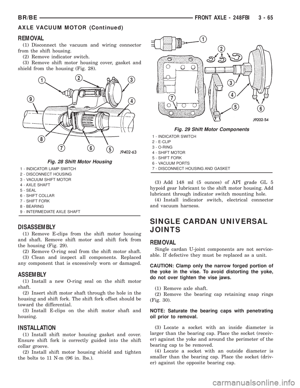
(3) Remove shift motor housing cover, gasket and
shield from the housing (Fig. 28).
DISASSEMBLY
(1) Remove E-clips from the shift motor housing
and shaft. Remove shift motor and shift fork from
the housing (Fig. 29).
(2) Remove O-ring seal from the shift motor shaft.
(3) Clean and inspect all components. Replaced
any component that is excessively worn or damaged.
ASSEMBLY
(1) Install a new O-ring seal on the shift motor
shaft.
(2) Insert shift motor shaft through the hole in the
housing and shift fork. The shift fork offset should be
toward the differential.
(3) Install E-clips on the shift motor shaft and
housing.
INSTALLATION
(1) Install shift motor housing gasket and cover.
Ensure shift fork is correctly guided into the shift
collar groove.
(2) Install shift motor housing shield and tighten
the bolts to 11 N´m (96 in. lbs.).(3) Add 148 ml (5 ounces) of API grade GL 5
hypoid gear lubricant to the shift motor housing. Add
lubricant through indicator switch mounting hole.
(4) Install indicator switch, electrical connector
and vacuum harness.
SINGLE CARDAN UNIVERSAL
JOINTS
REMOVAL
Single cardan U-joint components are not service-
able. If defective they must be replaced as a unit.
CAUTION: Clamp only the narrow forged portion of
the yoke in the vise. To avoid distorting the yoke,
do not over tighten the vise jaws.
(1) Remove axle shaft.
(2) Remove the bearing cap retaining snap rings
(Fig. 30).
NOTE: Saturate the bearing caps with penetrating
oil prior to removal.
(3) Locate a socket with an inside diameter is
larger than the bearing cap. Place the socket (receiv-
er) against the yoke and around the perimeter of the
bearing cap to be removed.
(4) Locate a socket with an outside diameter is
smaller than the bearing cap. Place the socket (driv-
er) against the opposite bearing cap.
Fig. 28 Shift Motor Housing
1 - INDICATOR LAMP SWITCH
2 - DISCONNECT HOUSING
3 - VACUUM SHIFT MOTOR
4 - AXLE SHAFT
5 - SEAL
6 - SHIFT COLLAR
7 - SHIFT FORK
8 - BEARING
9 - INTERMEDIATE AXLE SHAFT
Fig. 29 Shift Motor Components
1 - INDICATOR SWITCH
2 - E-CLIP
3 - O-RING
4 - SHIFT MOTOR
5 - SHIFT FORK
6 - VACUUM PORTS
7 - DISCONNECT HOUSING AND GASKET
BR/BEFRONT AXLE - 248FBI 3 - 65
AXLE VACUUM MOTOR (Continued)
Page 145 of 2889
PINION GEAR/RING GEAR
REMOVAL
NOTE: The ring and pinion gears are service in a
matched set. Do not replace the ring gear without
replacing the pinion gear.
(1) Raise and support the vehicle.
(2) Remove differential from housing.
(3) Place differential case in a vise with soft metal
jaw.
(4) Remove ring gear bolts from differential case.
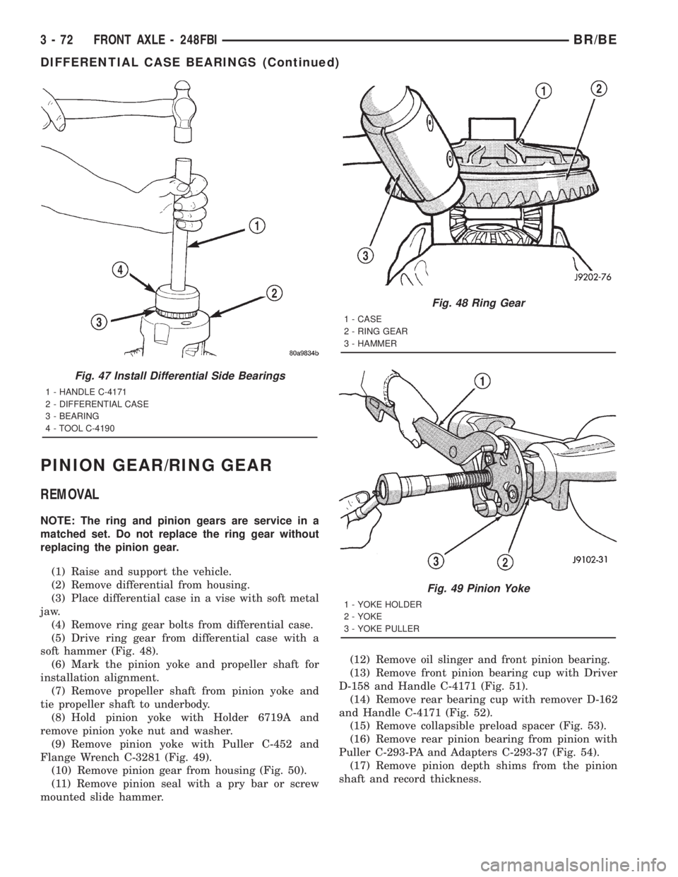
(5) Drive ring gear from differential case with a
soft hammer (Fig. 48).
(6) Mark the pinion yoke and propeller shaft for
installation alignment.
(7) Remove propeller shaft from pinion yoke and
tie propeller shaft to underbody.
(8) Hold pinion yoke with Holder 6719A and
remove pinion yoke nut and washer.
(9) Remove pinion yoke with Puller C-452 and
Flange Wrench C-3281 (Fig. 49).
(10) Remove pinion gear from housing (Fig. 50).
(11) Remove pinion seal with a pry bar or screw
mounted slide hammer.(12) Remove oil slinger and front pinion bearing.
(13) Remove front pinion bearing cup with Driver
D-158 and Handle C-4171 (Fig. 51).
(14) Remove rear bearing cup with remover D-162
and Handle C-4171 (Fig. 52).
(15) Remove collapsible preload spacer (Fig. 53).
(16) Remove rear pinion bearing from pinion with
Puller C-293-PA and Adapters C-293-37 (Fig. 54).
(17) Remove pinion depth shims from the pinion
shaft and record thickness.
Fig. 47 Install Differential Side Bearings
1 - HANDLE C-4171
2 - DIFFERENTIAL CASE
3 - BEARING
4 - TOOL C-4190
Fig. 48 Ring Gear
1 - CASE
2 - RING GEAR
3 - HAMMER
Fig. 49 Pinion Yoke
1 - YOKE HOLDER
2 - YOKE
3 - YOKE PULLER
3 - 72 FRONT AXLE - 248FBIBR/BE
DIFFERENTIAL CASE BEARINGS (Continued)
Page 150 of 2889
REAR AXLE-91/4
TABLE OF CONTENTS
page page
REAR AXLE-91/4
DESCRIPTION...........................77
OPERATION.............................77
DIAGNOSIS AND TESTING.................80
AXLE................................80
REMOVAL..............................83
INSTALLATION...........................84
ADJUSTMENTS..........................84
SPECIFICATIONS........................90
SPECIAL TOOLS.........................90
AXLE SHAFTS
REMOVAL..............................93
INSTALLATION...........................93
AXLE SHAFT SEALS
REMOVAL..............................94
INSTALLATION...........................94
AXLE BEARINGS
REMOVAL..............................94
INSTALLATION...........................95PINION SEAL
REMOVAL..............................95
INSTALLATION...........................95
DIFFERENTIAL
REMOVAL..............................96
DISASSEMBLY...........................97
ASSEMBLY.............................98
INSTALLATION...........................98
DIFFERENTIAL - TRAC-LOK
DIAGNOSIS AND TESTING.................98
TRAC-LOK............................98
DISASSEMBLY...........................99
ASSEMBLY............................101
DIFFERENTIAL CASE BEARINGS
REMOVAL.............................103
INSTALLATION..........................103
PINION GEAR/RING GEAR/TONE RING
REMOVAL.............................103
INSTALLATION..........................105
REAR AXLE-91/4
DESCRIPTION
The 9 1/4 Inch axle housings consist of a cast iron
center section with axle tubes extending from either
side. The tubes are pressed into and welded to the
differential housing to form a one-piece axle housing
(Fig. 1).
The axles have a vent hose to relieve internal pres-
sure caused by lubricant vaporization and internal
expansion.
The axles are equipped with semi-floating axle
shafts, meaning vehicle loads are supported by the
axle shaft and bearings. The axle shafts are retained
by C-locks in the differential side gears.
The removable, stamped steel cover provides a
means for inspection and service without removing
the complete axle from the vehicle.
The axle has a date tag and a gear ratio tag. The
tags are attached to the differential housing by a
cover bolt.
The rear wheel anti-lock (RWAL) brake speed sen-
sor is attached to the top, forward exterior of the dif-
ferential housing. A seal is located between the
sensor and the wire harness connector. The seal must
be in place when the wire connector is connected to
the sensor. The RWAL brake exciter ring is press-fit-ted onto the differential case against the ring gear
flange.
The differential case is a one-piece design. The dif-
ferential pinion shaft is retained with a screw. Differ-
ential bearing preload and ring gear backlash are set
and maintained by threaded adjusters at the outside
of the differential housing. Pinion bearing preload is
set and maintained by the use of a collapsible spacer.
Axles equipped with a Trac-Lokydifferential are
optional. A differential has a one-piece differential
case, and the same internal components as a stan-
dard differential, plus two clutch disc packs.
AXLE IDENTIFICATION
The axle differential cover can be used for identifi-
cation of the axle (Fig. 2). A ratio tag is attached to
the top of the differential cover.
OPERATION
The axle receives power from the transmission/
transfer case through the rear propeller shaft. The
rear propeller shaft is connected to the drive pinion
which rotates the differential through the gear mesh
with the ring gear bolted to the differential case. The
engine power is transmitted to the axle shafts
through the differential pinions and side gears. The
side gears are splined to the axle shafts.
BR/BEREAR AXLE - 9 1/4 3 - 77
Page 155 of 2889
DIAGNOSTIC CHART
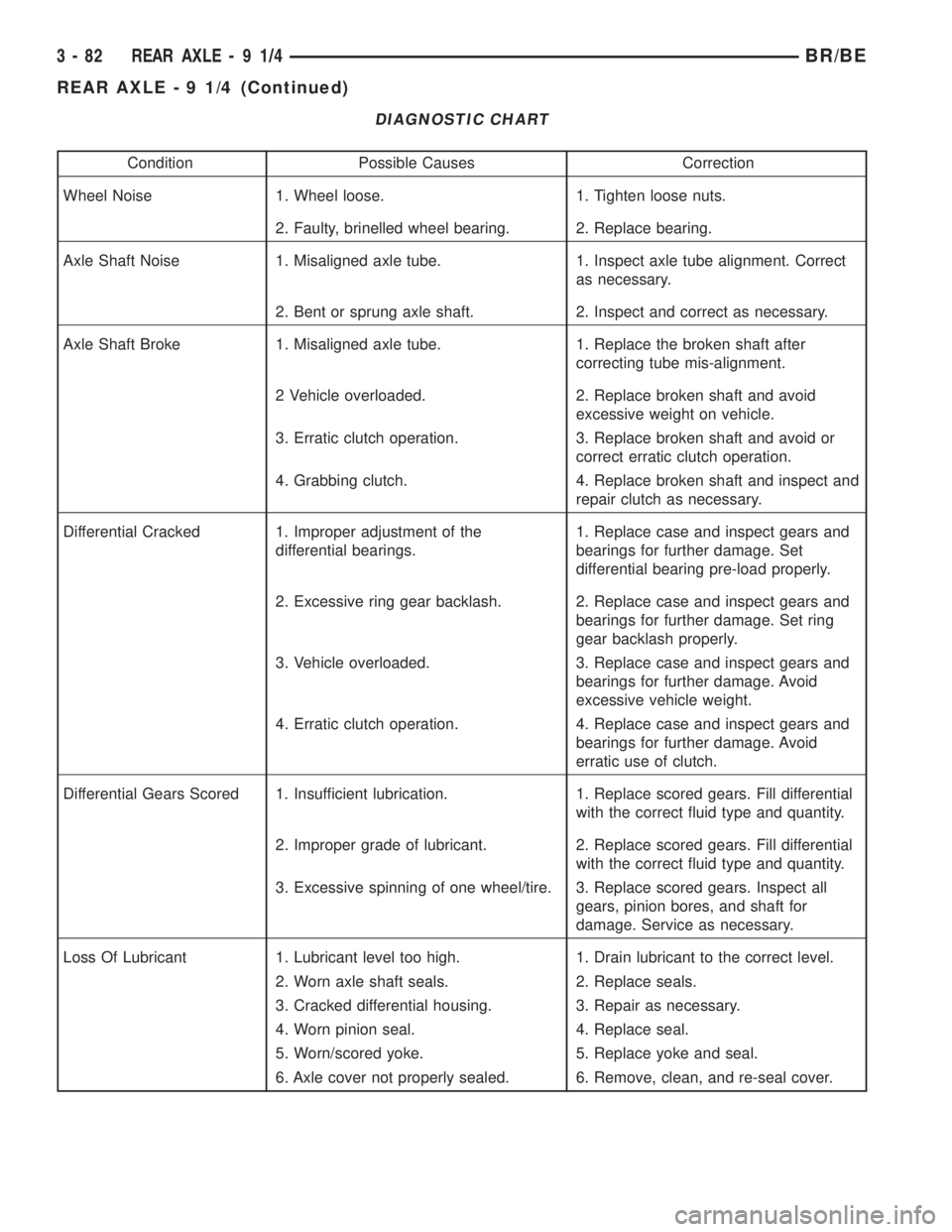
Condition Possible Causes Correction
Wheel Noise 1. Wheel loose. 1. Tighten loose nuts.
2. Faulty, brinelled wheel bearing. 2. Replace bearing.
Axle Shaft Noise 1. Misaligned axle tube. 1. Inspect axle tube alignment. Correct
as necessary.
2. Bent or sprung axle shaft. 2. Inspect and correct as necessary.
Axle Shaft Broke 1. Misaligned axle tube. 1. Replace the broken shaft after
correcting tube mis-alignment.
2 Vehicle overloaded. 2. Replace broken shaft and avoid
excessive weight on vehicle.
3. Erratic clutch operation. 3. Replace broken shaft and avoid or
correct erratic clutch operation.
4. Grabbing clutch. 4. Replace broken shaft and inspect and
repair clutch as necessary.
Differential Cracked 1. Improper adjustment of the
differential bearings.1. Replace case and inspect gears and
bearings for further damage. Set
differential bearing pre-load properly.
2. Excessive ring gear backlash. 2. Replace case and inspect gears and
bearings for further damage. Set ring
gear backlash properly.
3. Vehicle overloaded. 3. Replace case and inspect gears and
bearings for further damage. Avoid
excessive vehicle weight.
4. Erratic clutch operation. 4. Replace case and inspect gears and
bearings for further damage. Avoid
erratic use of clutch.
Differential Gears Scored 1. Insufficient lubrication. 1. Replace scored gears. Fill differential
with the correct fluid type and quantity.
2. Improper grade of lubricant. 2. Replace scored gears. Fill differential
with the correct fluid type and quantity.
3. Excessive spinning of one wheel/tire. 3. Replace scored gears. Inspect all
gears, pinion bores, and shaft for
damage. Service as necessary.
Loss Of Lubricant 1. Lubricant level too high. 1. Drain lubricant to the correct level.
2. Worn axle shaft seals. 2. Replace seals.
3. Cracked differential housing. 3. Repair as necessary.
4. Worn pinion seal. 4. Replace seal.
5. Worn/scored yoke. 5. Replace yoke and seal.
6. Axle cover not properly sealed. 6. Remove, clean, and re-seal cover.
3 - 82 REAR AXLE-91/4BR/BE
REAR AXLE - 9 1/4 (Continued)
Page 158 of 2889
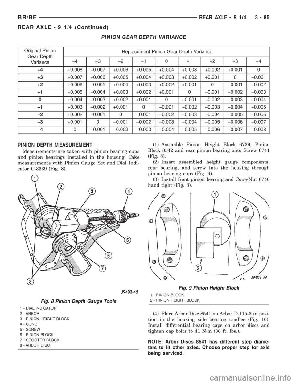
PINION GEAR DEPTH VARIANCE
Original Pinion
Gear Depth
VarianceReplacement Pinion Gear Depth Variance
þ4 þ3 þ2 þ1 0 +1 +2 +3 +4
+4+0.008 +0.007 +0.006 +0.005 +0.004 +0.003 +0.002 +0.001 0
+3+0.007 +0.006 +0.005 +0.004 +0.003 +0.002 +0.001 0 þ0.001
+2+0.006 +0.005 +0.004 +0.003 +0.002 +0.001 0 þ0.001 þ0.002
+1+0.005 +0.004 +0.003 +0.002 +0.001 0 þ0.001 þ0.002 þ0.003
0+0.004 +0.003 +0.002 +0.001 0 þ0.001 þ0.002 þ0.003 þ0.004
þ1+0.003 +0.002 +0.001 0 þ0.001 þ0.002 þ0.003 þ0.004 þ0.005
þ2+0.002 +0.001 0 þ0.001 þ0.002 þ0.003 þ0.004 þ0.005 þ0.006
þ3+0.001 0 þ0.001 þ0.002 þ0.003 þ0.004 þ0.005 þ0.006 þ0.007
þ40 þ0.001 þ0.002 þ0.003 þ0.004 þ0.005 þ0.006 þ0.007 þ0.008
PINION DEPTH MEASUREMENT
Measurements are taken with pinion bearing cups
and pinion bearings installed in the housing. Take
measurements with Pinion Gauge Set and Dial Indi-
cator C-3339 (Fig. 8).(1) Assemble Pinion Height Block 6739, Pinion
Block 8542 and rear pinion bearing onto Screw 6741
(Fig. 8).
(2) Insert assembled height gauge components,
rear bearing, and screw into the housing through
pinion bearing cups (Fig. 9).
(3) Install front pinion bearing and Cone-Nut 6740
hand tight (Fig. 8).
(4) Place Arbor Disc 8541 on Arbor D-115-3 in posi-
tion in the housing side bearing cradles (Fig. 10).
Install differential bearing caps on arbor discs and
tighten cap bolts to 41 N´m (30 ft. lbs.).
NOTE: Arbor Discs 8541 has different step diame-
ters to fit other axles. Choose proper step for axle
being serviced.
Fig. 8 Pinion Depth Gauge Tools
1 - DIAL INDICATOR
2 - ARBOR
3 - PINION HEIGHT BLOCK
4 - CONE
5 - SCREW
6 - PINION BLOCK
7 - SCOOTER BLOCK
8 - ARBOR DISC
Fig. 9 Pinion Height Block
1 - PINION BLOCK
2 - PINION HEIGHT BLOCK
BR/BEREAR AXLE - 9 1/4 3 - 85
REAR AXLE - 9 1/4 (Continued)