2001 DODGE RAM fuel cap release
[x] Cancel search: fuel cap releasePage 1497 of 2889
DIAGNOSIS AND TESTING - FUEL PUMP
PRESSURE TEST
Use this test in conjunction with the Fuel Pump
Capacity Test, Fuel Pressure Leak Down Test and Fuel
Pump Amperage Test found elsewhere in this group.
Check Valve Operation:The electric fuel pump
outlet contains a one-way check valve to prevent fuel
flow back into the tank and to maintain fuel supply
line pressure (engine warm) when pump is not oper-
ational. It is also used to keep the fuel supply line
full of gasoline when pump is not operational. After
the vehicle has cooled down, fuel pressure may drop
to 0 psi (cold fluid contracts), but liquid gasoline will
remain in fuel supply line between the check valve
and fuel injectors.Fuel pressure that has
dropped to 0 psi on a cooled down vehicle
(engine off) is a normal condition.When the elec-
tric fuel pump is activated, fuel pressure should
immediately(1±2 seconds) rise to specification.
All fuel systems are equipped with a fuel tank
module mounted, combination fuel filter/fuel pressure
regulator. The fuel pressure regulator is not con-
trolled by engine vacuum.
WARNING: THE FUEL SYSTEM IS UNDER CON-
STANT FUEL PRESSURE EVEN WITH THE ENGINE
OFF. BEFORE DISCONNECTING FUEL LINE AT
FUEL RAIL, THIS PRESSURE MUST BE RELEASED.
REFER TO THE FUEL SYSTEM PRESSURE
RELEASE PROCEDURE.
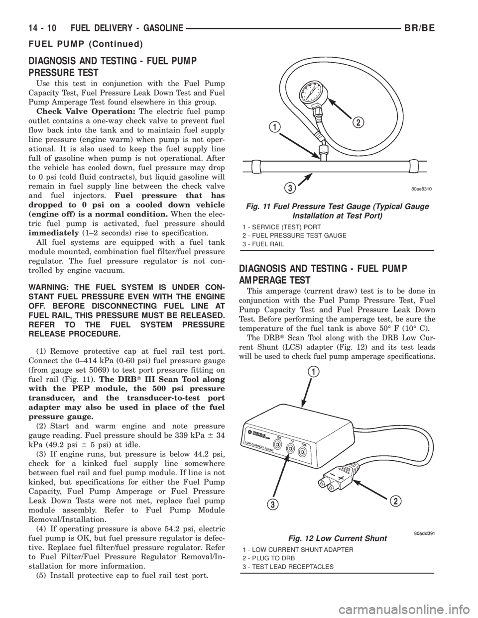
(1) Remove protective cap at fuel rail test port.
Connect the 0±414 kPa (0-60 psi) fuel pressure gauge
(from gauge set 5069) to test port pressure fitting on
fuel rail (Fig. 11).The DRBtIII Scan Tool along
with the PEP module, the 500 psi pressure
transducer, and the transducer-to-test port
adapter may also be used in place of the fuel
pressure gauge.
(2) Start and warm engine and note pressure
gauge reading. Fuel pressure should be 339 kPa634
kPa (49.2 psi65 psi) at idle.
(3) If engine runs, but pressure is below 44.2 psi,
check for a kinked fuel supply line somewhere
between fuel rail and fuel pump module. If line is not
kinked, but specifications for either the Fuel Pump
Capacity, Fuel Pump Amperage or Fuel Pressure
Leak Down Tests were not met, replace fuel pump
module assembly. Refer to Fuel Pump Module
Removal/Installation.
(4) If operating pressure is above 54.2 psi, electric
fuel pump is OK, but fuel pressure regulator is defec-
tive. Replace fuel filter/fuel pressure regulator. Refer
to Fuel Filter/Fuel Pressure Regulator Removal/In-
stallation for more information.
(5) Install protective cap to fuel rail test port.
DIAGNOSIS AND TESTING - FUEL PUMP
AMPERAGE TEST
This amperage (current draw) test is to be done in
conjunction with the Fuel Pump Pressure Test, Fuel
Pump Capacity Test and Fuel Pressure Leak Down
Test. Before performing the amperage test, be sure the
temperature of the fuel tank is above 50É F (10É C).
The DRBtScan Tool along with the DRB Low Cur-
rent Shunt (LCS) adapter (Fig. 12) and its test leads
will be used to check fuel pump amperage specifications.
Fig. 11 Fuel Pressure Test Gauge (Typical Gauge
Installation at Test Port)
1 - SERVICE (TEST) PORT
2 - FUEL PRESSURE TEST GAUGE
3 - FUEL RAIL
Fig. 12 Low Current Shunt
1 - LOW CURRENT SHUNT ADAPTER
2 - PLUG TO DRB
3 - TEST LEAD RECEPTACLES
14 - 10 FUEL DELIVERY - GASOLINEBR/BE
FUEL PUMP (Continued)
Page 1500 of 2889
OPERATION
Refer to Fuel Pump, Fuel Filter/Fuel Pressure Reg-
ulator and Fuel Gauge Sending Unit.
REMOVAL
WARNING: THE FUEL SYSTEM IS UNDER A CON-
STANT PRESSURE (EVEN WITH THE ENGINE OFF).
BEFORE SERVICING THE FUEL PUMP MODULE,
THE FUEL SYSTEM PRESSURE MUST BE
RELEASED.
(1) Drain and remove fuel tank. Refer to Fuel
Tank - All Engines in the Removal/Installation sec-
tion.
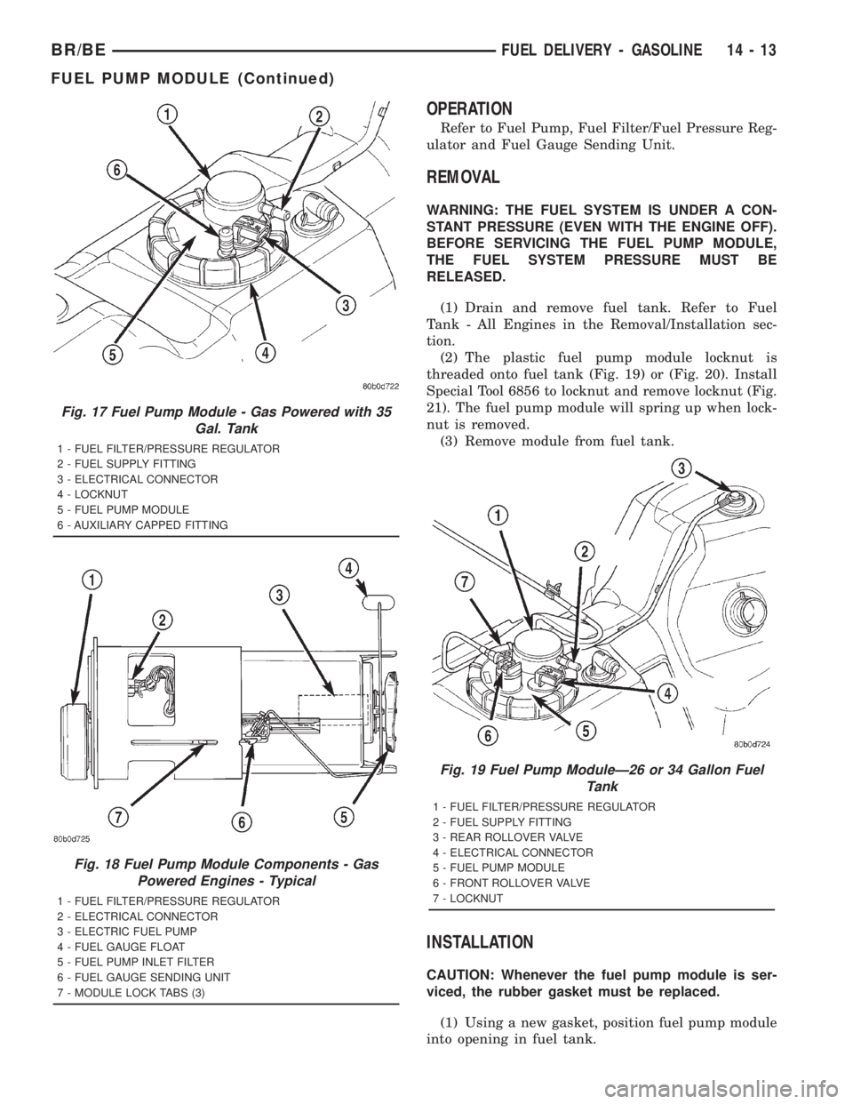
(2) The plastic fuel pump module locknut is
threaded onto fuel tank (Fig. 19) or (Fig. 20). Install
Special Tool 6856 to locknut and remove locknut (Fig.
21). The fuel pump module will spring up when lock-
nut is removed.
(3) Remove module from fuel tank.
INSTALLATION
CAUTION: Whenever the fuel pump module is ser-
viced, the rubber gasket must be replaced.
(1) Using a new gasket, position fuel pump module
into opening in fuel tank.
Fig. 17 Fuel Pump Module - Gas Powered with 35
Gal. Tank
1 - FUEL FILTER/PRESSURE REGULATOR
2 - FUEL SUPPLY FITTING
3 - ELECTRICAL CONNECTOR
4 - LOCKNUT
5 - FUEL PUMP MODULE
6 - AUXILIARY CAPPED FITTING
Fig. 18 Fuel Pump Module Components - Gas
Powered Engines - Typical
1 - FUEL FILTER/PRESSURE REGULATOR
2 - ELECTRICAL CONNECTOR
3 - ELECTRIC FUEL PUMP
4 - FUEL GAUGE FLOAT
5 - FUEL PUMP INLET FILTER
6 - FUEL GAUGE SENDING UNIT
7 - MODULE LOCK TABS (3)
Fig. 19 Fuel Pump ModuleÐ26 or 34 Gallon Fuel
Tank
1 - FUEL FILTER/PRESSURE REGULATOR
2 - FUEL SUPPLY FITTING
3 - REAR ROLLOVER VALVE
4 - ELECTRICAL CONNECTOR
5 - FUEL PUMP MODULE
6 - FRONT ROLLOVER VALVE
7 - LOCKNUT
BR/BEFUEL DELIVERY - GASOLINE 14 - 13
FUEL PUMP MODULE (Continued)
Page 1506 of 2889
INSTALLATION - 8.0L
(1) Apply a small amount of engine oil to each fuel
injector o-ring. This will help in fuel rail installation.
(2) Install injector(s) and injector clip(s) to fuel
rail.
NOTE: The fuel injector electrical connectors on all
10 injectors should be facing to the right (passen-
ger) side of the vehicle (Fig. 34).
(3) Position the fuel rail/fuel injector assembly to
the injector openings on the intake manifold.
(4) Guide each injector into the intake manifold.
Be careful not to tear the injector o-ring.
(5) Push therightfuel rail down until fuel injec-
tors have bottomed on injector shoulder. Push the
leftfuel rail down until fuel injectors have bottomed
on injector shoulder.
(6) Install the six fuel rail mounting bolts into the
lower half of intake manifold. Tighten bolts to 15
N´m (136 in. lbs.) torque.
(7) Connect electrical connectors at all fuel injec-
tors. To install connector, refer to (Fig. 33). Push con-
nector onto injector (1) and then push and lock red
colored slider (2). Verify connector is locked to injec-
tor by lightly tugging on connector. The injector wir-
ing harness is numerically tagged.
(8) Install upper half of intake manifold. Refer to
Engines for procedures.
(9) Connect main fuel line at fuel rail. Refer to
Quick-Connect Fittings for procedures.
(10) Install ignition coil pack and bracket assem-
bly at intake manifold and right engine valve cover
(four bolts).
(11) Install throttle body to intake manifold. Refer
to Throttle Body removal in this group.
(12) Install throttle body linkage to throttle body.
(13) Install air cleaner tube and housing.
(14) Install negative battery cable at battery.
(15) Start engine and check for leaks.
FUEL TANK
DESCRIPTION
The fuel tank is constructed of a plastic material.
Its main functions are for fuel storage and for place-
ment of the fuel pump module.
OPERATION
All models pass a full 360 degree rollover test
without fuel leakage. To accomplish this, fuel and
vapor flow controls are required for all fuel tank con-
nections.A rollover valve(s) is mounted into the top of the
fuel tank (or pump module). Refer to Emission Con-
trol System for rollover valve information.
An evaporation control system is connected to the
rollover valve(s) to reduce emissions of fuel vapors
into the atmosphere. When fuel evaporates from the
fuel tank, vapors pass through vent hoses or tubes to
a charcoal canister where they are temporarily held.
When the engine is running, the vapors are drawn
into the intake manifold. Certain models are also
equipped with a self-diagnosing system using a Leak
Detection Pump (LDP). Refer to Emission Control
System for additional information.
REMOVAL
WARNING: GASOLINE POWERED ENGINES: THE
FUEL SYSTEM IS UNDER A CONSTANT PRESSURE
EVEN WITH THE ENGINE OFF. BEFORE SERVICING
THE FUEL TANK, FUEL SYSTEM PRESSURE MUST
BE RELEASED. REFER TO THE FUEL SYSTEM
PRESSURE RELEASE PROCEDURE BEFORE SER-
VICING THE FUEL TANK.
Two different procedures may be used to drain fuel
tank (lowering tank or using DRB scan tool). When
equipped with a diesel engine, the DRB scan tool
cannot be used (no electric fuel pump).
The quickest draining procedure involves lowering
the fuel tank.
Gasoline Powered Engines:As an alternative
procedure, the electric fuel pump may be activated
allowing tank to be drained at fuel rail connection.
Refer to DRB scan tool for fuel pump activation pro-
cedures. Before disconnecting fuel line at fuel rail,
release fuel pressure. Refer to the Fuel System Pres-
sure Release Procedure in this group for procedures.
Attach end of special test hose tool number 6541,
6539, 6631 or 6923 at fuel rail disconnection (tool
number will depend on model and/or engine applica-
tion). Position opposite end of this hose tool to an
approved gasoline draining station. Activate fuel
pump and drain tank until empty.
If electric fuel pump is not operating, tank must be
lowered for fuel draining. Refer to following proce-
dures.
(1) Remove fuel tank filler tube cap.
(2) Perform Fuel System Pressure Release proce-
dure as described in this group.
(3) Gasoline Engines: Disconnect negative battery
cable at battery. Diesel Engines: Disconnect both neg-
ative battery cables at both batteries.
(4) Raise vehicle on hoist.
(5) Certain models are equipped with a separate
grounding wire (strap) connecting the fuel fill tube
assembly to the body. Disconnect wire by removing
screw.
BR/BEFUEL DELIVERY - GASOLINE 14 - 19
FUEL RAIL (Continued)
Page 1512 of 2889
(b) Type 2: Separate and unlatch 2 small arms
on end of clip (Fig. 47) and swing away from fuel
line.
(c) Slide latch clip toward fuel rail while lifting
with screwdriver.
(d) Insert special fuel line removal tool (Snap-On
number FIH 9055-1 or equivalent) into fuel line
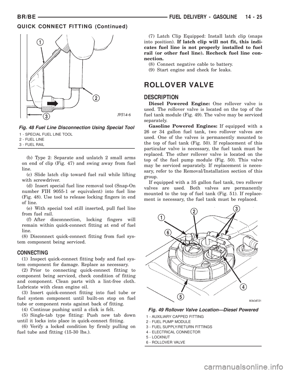
(Fig. 48). Use tool to release locking fingers in end
of line.
(e) With special tool still inserted, pull fuel line
from fuel rail.
(f) After disconnection, locking fingers will
remain within quick-connect fitting at end of fuel
line.
(8) Disconnect quick-connect fitting from fuel sys-
tem component being serviced.
CONNECTING
(1) Inspect quick-connect fitting body and fuel sys-
tem component for damage. Replace as necessary.
(2) Prior to connecting quick-connect fitting to
component being serviced, check condition of fitting
and component. Clean parts with a lint-free cloth.
Lubricate with clean engine oil.
(3) Insert quick-connect fitting into fuel tube or
fuel system component until built-on stop on fuel
tube or component rests against back of fitting.
(4) Continue pushing until a click is felt.
(5) Single-tab type fitting: Push new tab down
until it locks into place in quick-connect fitting.
(6) Verify a locked condition by firmly pulling on
fuel tube and fitting (15-30 lbs.).(7) Latch Clip Equipped: Install latch clip (snaps
into position).If latch clip will not fit, this indi-
cates fuel line is not properly installed to fuel
rail (or other fuel line). Recheck fuel line con-
nection.
(8) Connect negative cable to battery.
(9) Start engine and check for leaks.
ROLLOVER VALVE
DESCRIPTION
Diesel Powered Engine:One rollover valve is
used. The rollover valve is located on the top of the
fuel tank module (Fig. 49). The valve may be serviced
separately.
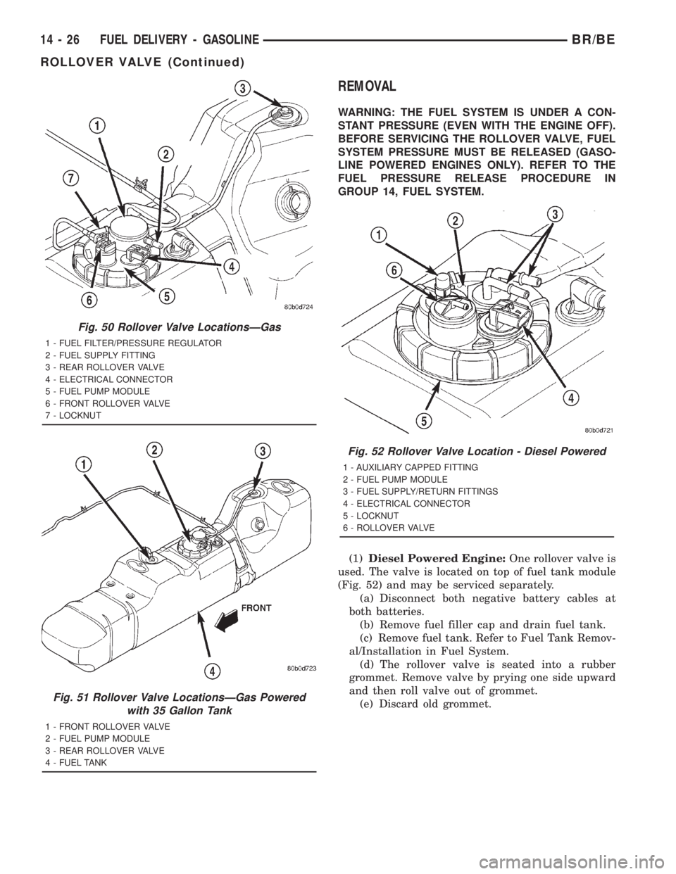
Gasoline Powered Engines:If equipped with a
26 or 34 gallon fuel tank, two rollover valves are
used. One of the valves is permanently mounted to
the top of fuel tank (Fig. 50). If replacement of this
particular valve is necessary, the fuel tank must be
replaced. The other rollover valve is located on the
top of the fuel pump module (Fig. 50). This valve
may be serviced separately. If replacement is neces-
sary, refer to the Removal/Installation section of this
group.
If equipped with a 35 gallon fuel tank, two rollover
valves are used. Both valves are permanently
mounted to the top of fuel tank (Fig. 51). If replace-
ment is necessary, the fuel tank must be replaced.
Fig. 48 Fuel Line Disconnection Using Special Tool
1 - SPECIAL FUEL LINE TOOL
2 - FUEL LINE
3 - FUEL RAIL
Fig. 49 Rollover Valve LocationÐDiesel Powered
1 - AUXILIARY CAPPED FITTING
2 - FUEL PUMP MODULE
3 - FUEL SUPPLY/RETURN FITTINGS
4 - ELECTRICAL CONNECTOR
5 - LOCKNUT
6 - ROLLOVER VALVE
BR/BEFUEL DELIVERY - GASOLINE 14 - 25
QUICK CONNECT FITTING (Continued)
Page 1513 of 2889
REMOVAL
WARNING: THE FUEL SYSTEM IS UNDER A CON-
STANT PRESSURE (EVEN WITH THE ENGINE OFF).
BEFORE SERVICING THE ROLLOVER VALVE, FUEL
SYSTEM PRESSURE MUST BE RELEASED (GASO-
LINE POWERED ENGINES ONLY). REFER TO THE
FUEL PRESSURE RELEASE PROCEDURE IN
GROUP 14, FUEL SYSTEM.
(1)Diesel Powered Engine:One rollover valve is
used. The valve is located on top of fuel tank module
(Fig. 52) and may be serviced separately.
(a) Disconnect both negative battery cables at
both batteries.
(b) Remove fuel filler cap and drain fuel tank.
(c) Remove fuel tank. Refer to Fuel Tank Remov-
al/Installation in Fuel System.
(d) The rollover valve is seated into a rubber
grommet. Remove valve by prying one side upward
and then roll valve out of grommet.
(e) Discard old grommet.
Fig. 50 Rollover Valve LocationsÐGas
1 - FUEL FILTER/PRESSURE REGULATOR
2 - FUEL SUPPLY FITTING
3 - REAR ROLLOVER VALVE
4 - ELECTRICAL CONNECTOR
5 - FUEL PUMP MODULE
6 - FRONT ROLLOVER VALVE
7 - LOCKNUT
Fig. 51 Rollover Valve LocationsÐGas Powered
with 35 Gallon Tank
1 - FRONT ROLLOVER VALVE
2 - FUEL PUMP MODULE
3 - REAR ROLLOVER VALVE
4 - FUEL TANK
Fig. 52 Rollover Valve Location - Diesel Powered
1 - AUXILIARY CAPPED FITTING
2 - FUEL PUMP MODULE
3 - FUEL SUPPLY/RETURN FITTINGS
4 - ELECTRICAL CONNECTOR
5 - LOCKNUT
6 - ROLLOVER VALVE
14 - 26 FUEL DELIVERY - GASOLINEBR/BE
ROLLOVER VALVE (Continued)
Page 1544 of 2889
STANDARD PROCEDURES - CLEANING FUEL
SYSTEM PARTS
CAUTION: Cleanliness cannot be overemphasized
when handling or replacing diesel fuel system com-
ponents. This especially includes the fuel injectors,
high-pressure fuel lines and fuel injection pump.
Very tight tolerances are used with these parts. Dirt
contamination could cause rapid part wear and pos-
sible plugging of fuel injector nozzle tip holes. This
in turn could lead to possible engine misfire.
Always wash/clean any fuel system component
thoroughly before disassembly and then air dry.
Cap or cover any open part after disassembly.
Before assembly, examine each part for dirt, grease
or other contaminants and clean if necessary. When
installing new parts, lubricate them with clean
engine oil or clean diesel fuel only.
STANDARD PROCEDURE - AIR BLEED
A certain amount of air becomes trapped in the
fuel system when fuel system components on the
supply and/or high-pressure side are serviced or
replaced. Primary air bleeding is accomplished using
the electric fuel transfer (lift) pump. If the vehicle
has been allowed to run completely out of fuel, the
fuel injectors must also be bled as the fuel injection
pumpis notself-bleeding (priming).
Servicing or replacing components on the fuel
return side will not require air bleeding.
WARNING: DO NOT BLEED AIR FROM THE FUEL
SYSTEM OF A HOT ENGINE.
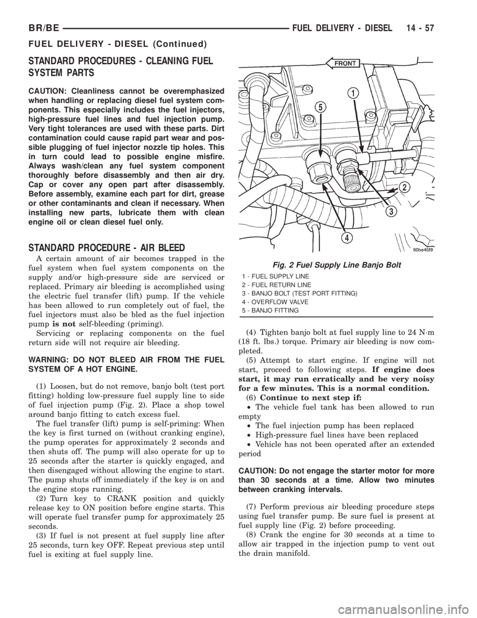
(1) Loosen, but do not remove, banjo bolt (test port
fitting) holding low-pressure fuel supply line to side
of fuel injection pump (Fig. 2). Place a shop towel
around banjo fitting to catch excess fuel.
The fuel transfer (lift) pump is self-priming: When
the key is first turned on (without cranking engine),
the pump operates for approximately 2 seconds and
then shuts off. The pump will also operate for up to
25 seconds after the starter is quickly engaged, and
then disengaged without allowing the engine to start.
The pump shuts off immediately if the key is on and
the engine stops running.
(2) Turn key to CRANK position and quickly
release key to ON position before engine starts. This
will operate fuel transfer pump for approximately 25
seconds.
(3) If fuel is not present at fuel supply line after
25 seconds, turn key OFF. Repeat previous step until
fuel is exiting at fuel supply line.(4) Tighten banjo bolt at fuel supply line to 24 N´m
(18 ft. lbs.) torque. Primary air bleeding is now com-
pleted.
(5) Attempt to start engine. If engine will not
start, proceed to following steps.If engine does
start, it may run erratically and be very noisy
for a few minutes. This is a normal condition.
(6)Continue to next step if:
²The vehicle fuel tank has been allowed to run
empty
²The fuel injection pump has been replaced
²High-pressure fuel lines have been replaced
²Vehicle has not been operated after an extended
period
CAUTION: Do not engage the starter motor for more
than 30 seconds at a time. Allow two minutes
between cranking intervals.
(7) Perform previous air bleeding procedure steps
using fuel transfer pump. Be sure fuel is present at
fuel supply line (Fig. 2) before proceeding.
(8) Crank the engine for 30 seconds at a time to
allow air trapped in the injection pump to vent out
the drain manifold.Fig. 2 Fuel Supply Line Banjo Bolt
1 - FUEL SUPPLY LINE
2 - FUEL RETURN LINE
3 - BANJO BOLT (TEST PORT FITTING)
4 - OVERFLOW VALVE
5 - BANJO FITTING
BR/BEFUEL DELIVERY - DIESEL 14 - 57
FUEL DELIVERY - DIESEL (Continued)
Page 1569 of 2889
(5) Using key, crank engine over while observing
gauge. Pressure should be 5±7 psi.
(6) Re-install fuel system relay to PDC.
(7) Start engine and record fuel pressure. Pressure
should be aminimumof 69 kPa (10 psi) at idle
speed.
(8) Because fuel pump relay was removed, a Diag-
nostic Trouble Code (DTC) may have been set. After
testing is completed, and relay has been installed,
use DRB scan tool to remove DTC.
Pressure Drop Test:
(9) Shut engine off and remove test gauge from
inlet port test fitting. Re-attach 6828 test gauge to
outlet port (Fig. 55). Start engine and record fuel
pressure. Pressure should not be more than 34 kPa
(5 psi) lower than inlet port pressure test. If so,
replace fuel filter.
Fuel Supply Restriction Test:
Due to very small vacuum specifications, the DRB
scan tool along with the Periphal Expansion Port
(PEP) Module and 0±15 psi transducer must be used.
(10) Verify transfer pump pressure is OK before
performing restriction test.
(11) Locate and disconnect fuel supply line quick-
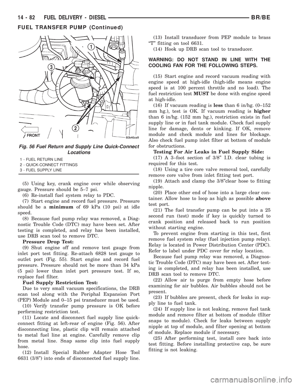
connect fitting at left-rear of engine (Fig. 56). After
disconnecting line, plastic clip will remain attached
to metal fuel line at engine. Carefully remove clip
from metal line. Snap same clip into fuel supply
hose.
(12) Install Special Rubber Adapter Hose Tool
6631 (3/8º) into ends of disconnected fuel supply line.(13) Install transducer from PEP module to brass
ªTº fitting on tool 6631.
(14) Hook up DRB scan tool to transducer.
WARNING: DO NOT STAND IN LINE WITH THE
COOLING FAN FOR THE FOLLOWING STEPS.
(15) Start engine and record vacuum reading with
engine speed at high-idle (high-idle means engine
speed is at 100 percent throttle and no load). The
fuel restriction testMUSTbe done with engine speed
at high-idle.
(16) If vacuum reading islessthan 6 in/hg. (0±152
mm hg.), test is OK. If vacuum reading ishigher
than 6 in/hg. (152 mm hg.), restriction exists in fuel
supply line or in fuel tank module. Check fuel supply
line for damage, dents or kinking. If OK, remove
module and check module and lines for blockage.
Also check fuel pump inlet filter at bottom of module
for obstructions.
Testing For Air Leaks in Fuel Supply Side:
(17) A 3±foot section of 3/8º I.D. clear tubing is
required for this test.
(18) Using a tire core valve removal tool, carefully
remove core valve from inlet fitting test port.
(19) Attach and clamp the 3/8ºclear hose to fitting
nipple.
(20) Place other end of hose into a large clear con-
tainer. Allow hose to loop as high as possibleabove
test port.
(21) The fuel transfer pump can be put into a 25
second run (test) mode if key is quickly turned to
crank position and released back to run position
without starting engine.
To prevent engine from starting in this test, first
remove fuel system relay (fuel injection pump relay).
Relay is located in Power Distribution Center (PDC).
Refer to label under PDC cover for relay location.
Because fuel pump relay was removed, a Diagnos-
tic Trouble Code (DTC) may have been set. After test-
ing is completed, and relay has been installed, use
DRB scan tool to remove DTC.
(22) Allow air to purge from empty hose before
examining for air bubbles. Air bubbles should not be
present.
(23) If bubbles are present, check for leaks in sup-
ply line to fuel tank.
(24) If supply line is not leaking, remove fuel tank
module and remove filter at bottom of module (filter
snaps to module). Check for leaks between supply
nipple at top of module, and filter opening at bottom
of module. Replace module if necessary.
(25) After performing test, install core back into
test fitting. Before installing protective cap, be sure
fitting is not leaking.
Fig. 56 Fuel Return and Supply Line Quick-Connect
Locations
1 - FUEL RETURN LINE
2 - QUICK-CONNECT FITTINGS
3 - FUEL SUPPLY LINE
14 - 82 FUEL DELIVERY - DIESELBR/BE
FUEL TRANSFER PUMP (Continued)
Page 2820 of 2889
FUEL FILLER CAP
DESCRIPTION
The plastic fuel tank filler tube cap is threaded
onto the end of the fuel fill tube. Certain models are
equipped with a 1/4 turn cap.
OPERATION
The loss of any fuel or vapor out of fuel filler tube
is prevented by the use of a pressure-vacuum fuel fill
cap. Relief valves inside the cap will release fuel tank
pressure at predetermined pressures. Fuel tank vac-
uum will also be released at predetermined values.
This cap must be replaced by a similar unit if
replacement is necessary. This is in order for the sys-
tem to remain effective.
CAUTION: Remove fill cap before servicing any fuel
system component to relieve tank pressure. If
equipped with a Leak Detection Pump (LDP), the
cap must be tightened securely. If cap is left loose,
a Diagnostic Trouble Code (DTC) may be set.
REMOVAL/INSTALLATION
If replacement of the 1/4 turn fuel tank filler tube
cap is necessary, it must be replaced with an identi-
cal cap to be sure of correct system operation.CAUTION: Remove the fuel tank filler tube cap to
relieve fuel tank pressure. The cap must be
removed prior to disconnecting any fuel system
component or before draining the fuel tank.
LEAK DETECTION PUMP
DESCRIPTION
The Leak Detection Pump (LDP) is used only with
certain emission packages.
The LDP is a device used to detect a leak in the
evaporative system.
The pump contains a 3 port solenoid, a pump that
contains a switch, a spring loaded canister vent valve
seal, 2 check valves and a spring/diaphragm.
Immediately after a cold start, engine temperature
between 40ÉF and 86ÉF, the 3 port solenoid is briefly
energized. This initializes the pump by drawing air
into the pump cavity and also closes the vent seal.
During non-test test conditions, the vent seal is held
open by the pump diaphragm assembly which pushes
it open at the full travel position. The vent seal will
remain closed while the pump is cycling. This is due
to the operation of the 3 port solenoid which prevents
the diaphragm assembly from reaching full travel.
After the brief initialization period, the solenoid is
de-energized, allowing atmospheric pressure to enter
the pump cavity. This permits the spring to drive the
diaphragm which forces air out of the pump cavity
and into the vent system. When the solenoid is ener-
gized and de-energized, the cycle is repeated creating
flow in typical diaphragm pump fashion. The pump
is controlled in 2 modes:
PUMP MODE:The pump is cycled at a fixed rate
to achieve a rapid pressure build in order to shorten
the overall test time.
TEST MODE:The solenoid is energized with a
fixed duration pulse. Subsequent fixed pulses occur
when the diaphragm reaches the switch closure
point.
The spring in the pump is set so that the system
will achieve an equalized pressure of about 7.5 inches
of water.
When the pump starts, the cycle rate is quite high.
As the system becomes pressurized pump rate drops. If
there is no leak the pump will quit. If there is a leak,
the test is terminated at the end of the test mode.
If there is no leak, the purge monitor is run. If the
cycle rate increases due to the flow through the
purge system, the test is passed and the diagnostic is
complete.
The canister vent valve will unseal the system
after completion of the test sequence as the pump
diaphragm assembly moves to the full travel position.
A typical system schematic is shown in (Fig. 3).
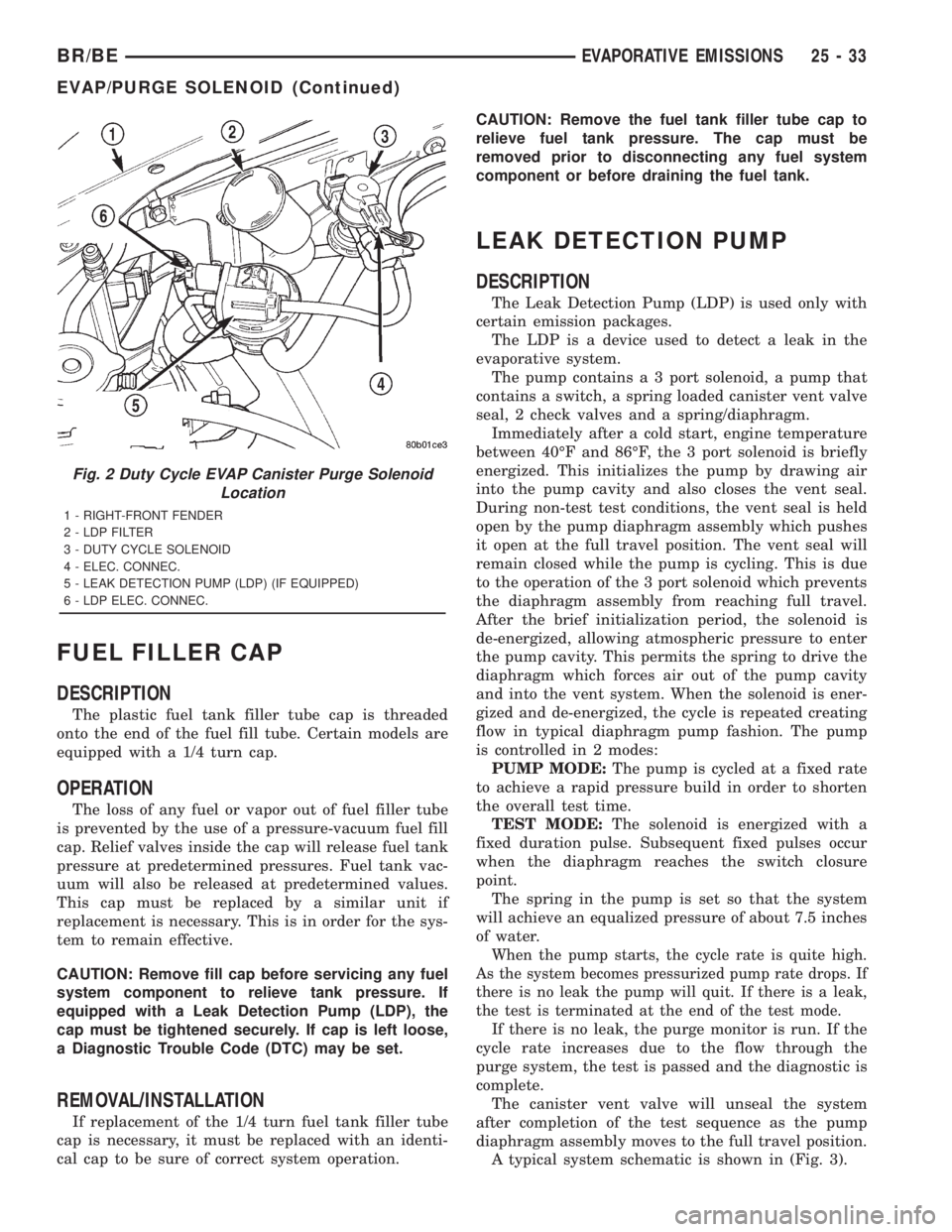
Fig. 2 Duty Cycle EVAP Canister Purge Solenoid
Location
1 - RIGHT-FRONT FENDER
2 - LDP FILTER
3 - DUTY CYCLE SOLENOID
4 - ELEC. CONNEC.
5 - LEAK DETECTION PUMP (LDP) (IF EQUIPPED)
6 - LDP ELEC. CONNEC.
BR/BEEVAPORATIVE EMISSIONS 25 - 33
EVAP/PURGE SOLENOID (Continued)