2001 DODGE RAM dimensions
[x] Cancel search: dimensionsPage 1411 of 2889
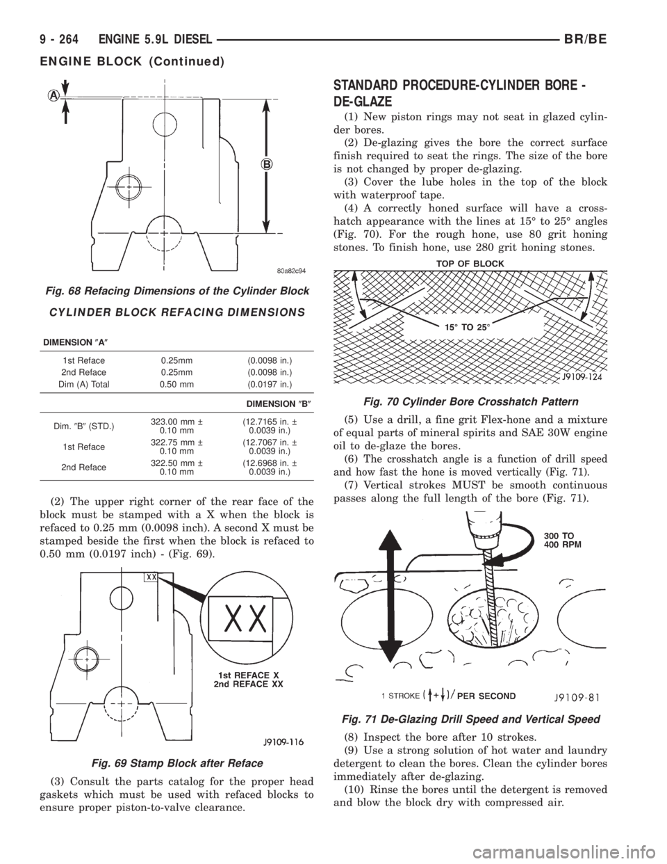
(2) The upper right corner of the rear face of the
block must be stamped with a X when the block is
refaced to 0.25 mm (0.0098 inch). A second X must be
stamped beside the first when the block is refaced to
0.50 mm (0.0197 inch) - (Fig. 69).
(3) Consult the parts catalog for the proper head
gaskets which must be used with refaced blocks to
ensure proper piston-to-valve clearance.
STANDARD PROCEDURE-CYLINDER BORE -
DE-GLAZE
(1) New piston rings may not seat in glazed cylin-
der bores.
(2) De-glazing gives the bore the correct surface
finish required to seat the rings. The size of the bore
is not changed by proper de-glazing.
(3) Cover the lube holes in the top of the block
with waterproof tape.
(4) A correctly honed surface will have a cross-
hatch appearance with the lines at 15É to 25É angles
(Fig. 70). For the rough hone, use 80 grit honing
stones. To finish hone, use 280 grit honing stones.
(5) Use a drill, a fine grit Flex-hone and a mixture
of equal parts of mineral spirits and SAE 30W engine
oil to de-glaze the bores.
(6)
The crosshatch angle is a function of drill speed
and how fast the hone is moved vertically (Fig. 71).
(7) Vertical strokes MUST be smooth continuous
passes along the full length of the bore (Fig. 71).
(8) Inspect the bore after 10 strokes.
(9) Use a strong solution of hot water and laundry
detergent to clean the bores. Clean the cylinder bores
immediately after de-glazing.
(10) Rinse the bores until the detergent is removed
and blow the block dry with compressed air.
Fig. 68 Refacing Dimensions of the Cylinder Block
CYLINDER BLOCK REFACING DIMENSIONS
DIMENSION(A(
1st Reface 0.25mm (0.0098 in.)
2nd Reface 0.25mm (0.0098 in.)
Dim (A) Total 0.50 mm (0.0197 in.)
DIMENSION(B(
Dim.9B9(STD.)323.00 mm
0.10 mm(12.7165 in.
0.0039 in.)
1st Reface322.75 mm
0.10 mm(12.7067 in.
0.0039 in.)
2nd Reface322.50 mm
0.10 mm(12.6968 in.
0.0039 in.)
Fig. 69 Stamp Block after Reface
Fig. 70 Cylinder Bore Crosshatch Pattern
Fig. 71 De-Glazing Drill Speed and Vertical Speed
9 - 264 ENGINE 5.9L DIESELBR/BE
ENGINE BLOCK (Continued)
Page 1412 of 2889
(11) Check the bore cleanliness by wiping with a
white, lint free, lightly oiled cloth. If grit residue is
still present, repeat the cleaning process until all res-
idue is removed. Wash the bores and the complete
block assembly with solvent and dry with compressed
air.
(12) Be sure to remove the tape covering the lube
holes after the cleaning process is complete.
STANDARD PROCEDUREÐCYLINDER BORE
REPAIR
Cylinder bore(s) can be repaired by one of two
methods:
²Method 1:ÐOver boring and using oversize pis-
tons and rings.
²Method 2:ÐBoring and installing a repair sleeve
to return the bore to standard dimensions.
METHOD 1ÐOVERSIZE BORE
Cylinder bore(s) can be repaired by one of two
methods:
Oversize pistons and rings are available in two
sizes - 0.50 mm (0.0197 inch) and 1.00 mm (0.0393
inch).
Any combination of standard, 0.50 mm (0.0197
inch) or 1.00 mm (0.0393 inch) overbore may be used
in the same engine.
If more than 1.00 mm (0.0393 inch) overbore is
needed, a repair sleeve can be installed (refer to
Method 2ÐRepair Sleeve).
Cylinder block bores may be bored twice before use
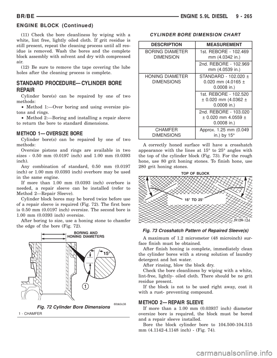
of a repair sleeve is required (Fig. 72). The first bore
is 0.50 mm (0.0197 inch) oversize. The second bore is
1.00 mm (0.0393 inch) oversize.
After boring to size, use a honing stone to chamfer
the edge of the bore (Fig. 72).
CYLINDER BORE DIMENSION CHART
DESCRIPTION MEASUREMENT
BORING DIAMETER
DIMENSION1st. REBORE - 102.469
mm (4.0342 in.)
2nd. REBORE - 102.969
mm (4.0539 in.)
HONING DIAMETER
DIMENSIONSSTANDARD - 102.020
0.020 mm (4.0165
0.0008 in.)
1st. REBORE - 102.520
0.020 mm (4.0362
0.0008 in.)
2nd. REBORE - 103.020
0.020 mm 4.0559
0.0008 in.)
CHAMFER
DIMENSIONSApprox. 1.25 mm (0.049
in.) by 15É
A correctly honed surface will have a crosshatch
appearance with the lines at 15É to 25É angles with
the top of the cylinder block (Fig. 73). For the rough
hone, use 80 grit honing stones. To finish hone, use
280 grit honing stones.
A maximum of 1.2 micrometer (48 microinch) sur-
face finish must be obtained.
After finish honing is complete, immediately clean
the cylinder bores with a strong solution of laundry
detergent and hot water.
After rinsing, blow the block dry.
Check the bore cleanliness by wiping with a white,
lint-free, lightly- oiled cloth. There should be no grit
residue present.
If the block is not to be used right away, coat it
with a rust- preventing compound.
METHOD 2ÐREPAIR SLEEVE
If more than a 1.00 mm (0.03937 inch) diameter
oversize bore is required, the block must be bored
and a repair sleeve installed.
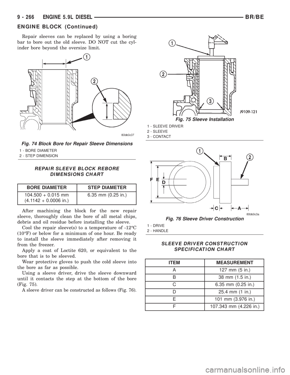
Bore the block cylinder bore to 104.500-104.515
mm (4.1142-4.1148 inch) - (Fig. 74).Fig. 72 Cylinder Bore Dimensions
1 - CHAMFER
Fig. 73 Crosshatch Pattern of Repaired Sleeve(s)
BR/BEENGINE 5.9L DIESEL 9 - 265
ENGINE BLOCK (Continued)
Page 1413 of 2889
Repair sleeves can be replaced by using a boring
bar to bore out the old sleeve. DO NOT cut the cyl-
inder bore beyond the oversize limit.
REPAIR SLEEVE BLOCK REBORE
DIMENSIONS CHART
BORE DIAMETER STEP DIAMETER
104.500 + 0.015 mm
(4.1142 + 0.0006 in.)6.35 mm (0.25 in.)
After machining the block for the new repair
sleeve, thoroughly clean the bore of all metal chips,
debris and oil residue before installing the sleeve.
Cool the repair sleeve(s) to a temperature of -12ÉC
(10ÉF) or below for a minimum of one hour. Be ready
to install the sleeve immediately after removing it
from the freezer.
Apply a coat of Loctite 620, or equivalent to the
bore that is to be sleeved.
Wear protective gloves to push the cold sleeve into
the bore as far as possible.
Using a sleeve driver, drive the sleeve downward
until it contacts the step at the bottom of the bore
(Fig. 75).
A sleeve driver can be constructed as follows (Fig. 76).
SLEEVE DRIVER CONSTRUCTION
SPECIFICATION CHART
ITEM MEASUREMENT
A 127 mm (5 in.)
B 38 mm (1.5 in.)
C 6.35 mm (0.25 in.)
D 25.4 mm (1 in.)
E 101 mm (3.976 in.)
F 107.343 mm (4.226 in.)
Fig. 74 Block Bore for Repair Sleeve Dimensions
1 - BORE DIAMETER
2 - STEP DIMENSION
Fig. 75 Sleeve Installation
1 - SLEEVE DRIVER
2 - SLEEVE
3 - CONTACT
Fig. 76 Sleeve Driver Construction
1 - DRIVE
2 - HANDLE
9 - 266 ENGINE 5.9L DIESELBR/BE
ENGINE BLOCK (Continued)
Page 1414 of 2889
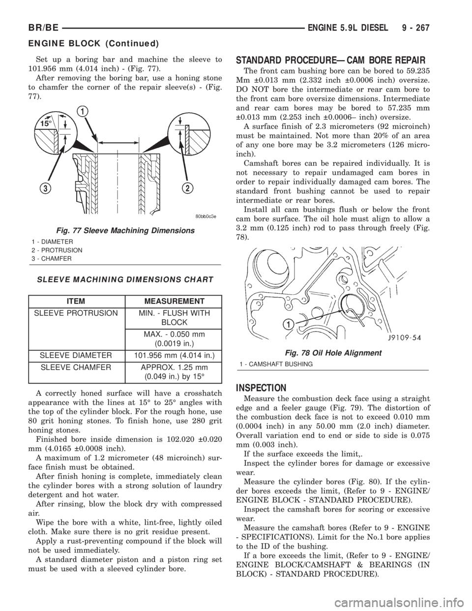
Set up a boring bar and machine the sleeve to
101.956 mm (4.014 inch) - (Fig. 77).
After removing the boring bar, use a honing stone
to chamfer the corner of the repair sleeve(s) - (Fig.
77).
SLEEVE MACHINING DIMENSIONS CHART
ITEM MEASUREMENT
SLEEVE PROTRUSION MIN. - FLUSH WITH
BLOCK
MAX. - 0.050 mm
(0.0019 in.)
SLEEVE DIAMETER 101.956 mm (4.014 in.)
SLEEVE CHAMFER APPROX. 1.25 mm
(0.049 in.) by 15É
A correctly honed surface will have a crosshatch
appearance with the lines at 15É to 25É angles with
the top of the cylinder block. For the rough hone, use
80 grit honing stones. To finish hone, use 280 grit
honing stones.
Finished bore inside dimension is 102.020 0.020
mm (4.0165 0.0008 inch).
A maximum of 1.2 micrometer (48 microinch) sur-
face finish must be obtained.
After finish honing is complete, immediately clean
the cylinder bores with a strong solution of laundry
detergent and hot water.
After rinsing, blow the block dry with compressed
air.
Wipe the bore with a white, lint-free, lightly oiled
cloth. Make sure there is no grit residue present.
Apply a rust-preventing compound if the block will
not be used immediately.
A standard diameter piston and a piston ring set
must be used with a sleeved cylinder bore.
STANDARD PROCEDUREÐCAM BORE REPAIR
The front cam bushing bore can be bored to 59.235
Mm 0.013 mm (2.332 inch 0.0006 inch) oversize.
DO NOT bore the intermediate or rear cam bore to
the front cam bore oversize dimensions. Intermediate
and rear cam bores may be bored to 57.235 mm
0.013 mm (2.253 inch 0.0006± inch) oversize.
A surface finish of 2.3 micrometers (92 microinch)
must be maintained. Not more than 20% of an area
of any one bore may be 3.2 micrometers (126 micro-
inch).
Camshaft bores can be repaired individually. It is
not necessary to repair undamaged cam bores in
order to repair individually damaged cam bores. The
standard front bushing cannot be used to repair
intermediate or rear bores.
Install all cam bushings flush or below the front
cam bore surface. The oil hole must align to allow a
3.2 mm (0.125 inch) rod to pass through freely (Fig.
78).
INSPECTION
Measure the combustion deck face using a straight
edge and a feeler gauge (Fig. 79). The distortion of
the combustion deck face is not to exceed 0.010 mm
(0.0004 inch) in any 50.00 mm (2.0 inch) diameter.
Overall variation end to end or side to side is 0.075
mm (0.003 inch).
If the surface exceeds the limit,.
Inspect the cylinder bores for damage or excessive
wear.
Measure the cylinder bores (Fig. 80). If the cylin-
der bores exceeds the limit, (Refer to 9 - ENGINE/
ENGINE BLOCK - STANDARD PROCEDURE).
Inspect the camshaft bores for scoring or excessive
wear.
Measure the camshaft bores (Refer to 9 - ENGINE
- SPECIFICATIONS). Limit for the No.1 bore applies
to the ID of the bushing.
If a bore exceeds the limit, (Refer to 9 - ENGINE/
ENGINE BLOCK/CAMSHAFT & BEARINGS (IN
BLOCK) - STANDARD PROCEDURE).
Fig. 77 Sleeve Machining Dimensions
1 - DIAMETER
2 - PROTRUSION
3 - CHAMFER
Fig. 78 Oil Hole Alignment
1 - CAMSHAFT BUSHING
BR/BEENGINE 5.9L DIESEL 9 - 267
ENGINE BLOCK (Continued)
Page 1482 of 2889
CAUTION: Do not reuse damaged fasteners, quality
of repair would be suspect. Do not drill holes in top
or bottom frame rail flanges, frame rail failure can
result. Do Not use softer than Grade 5 bolts to
replace production fasteners, loosening or failure
can result. When using heat to straighten frame
components do not exceed 566ÉC (1050ÉF), metal
fatigue can result. Welding the joints around riveted
cross members and frame side rails can weaken
frame.
FRAME STRAIGHTENING
When necessary, a conventional frame that is bent
or twisted can be straightened by application of heat.
The temperature must not exceed 566ÉC (1050ÉF).
The metal will have a dull red glow at the desired
temperature. Excessive heat will decrease the
strength of the metal and result in a weakened
frame.
Welding the joints around riveted cross members
and frame side rails is not recommended.
A straightening repair process should be limited to
frame members that are not severely damaged. The
replacement bolts, nuts and rivets that are used to
join the frame members should conform to the same
specifications as the original bolts, nuts and rivets.
FRAME REPAIRS
DRILLING HOLES
Do not drill holes in frame side rail top and bottom
flanges, metal fatigue can result causing frame fail-
ure. Holes drilled in the side of the frame rail must
be at least 38 mm (1.5 in.) from the top and bottom
flanges.
Additional drill holes should be located away from
existing holes.
WELDING
Use MIG, TIG or arc welding equipment to repair
welded frame components.
Frame components that have been damaged should
be inspected for cracks before returning the vehicle
to use. If cracks are found in accessible frame com-
ponents perform the following procedures.
(1) Drill a hole at each end of the crack with a 3
mm (O.125 in.) diameter drill bit.
(2) Using a suitable die grinder with 3 inch cut off
wheel, V-groove the crack to allow 100% weld pene-
tration.
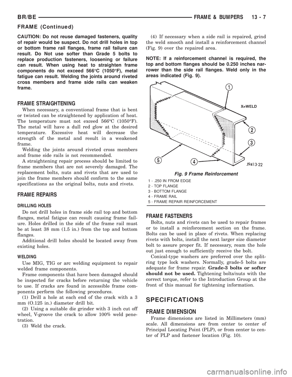
(3) Weld the crack.(4) If necessary when a side rail is repaired, grind
the weld smooth and install a reinforcement channel
(Fig. 9) over the repaired area.
NOTE: If a reinforcement channel is required, the
top and bottom flanges should be 0.250 inches nar-
rower than the side rail flanges. Weld only in the
areas indicated (Fig. 9).
FRAME FASTENERS
Bolts, nuts and rivets can be used to repair frames
or to install a reinforcement section on the frame.
Bolts can be used in place of rivets. When replacing
rivets with bolts, install the next larger size diameter
bolt to assure proper fit. If necessary, ream the hole
out just enough to sufficiently receive the bolt.
Conical-type washers are preferred over the split-
ring type lock washers. Normally, grade-5 bolts are
adequate for frame repair.Grade-3 bolts or softer
should not be used.Tightening bolts/nuts with the
correct torque, refer to the Introduction Group at the
front of this manual for tightening information.
SPECIFICATIONS
FRAME DIMENSION
Frame dimensions are listed in Millimeters (mm)
scale. All dimensions are from center to center of
Principal Locating Point (PLP), or from center to cen-
ter of PLP and fastener location (Fig. 10).
Fig. 9 Frame Reinforcement
1 - .250 IN FROM EDGE
2 - TOP FLANGE
3 - BOTTOM FLANGE
4 - FRAME RAIL
5 - FRAME REPAIR REINFORCEMENT
BR/BEFRAME & BUMPERS 13 - 7
FRAME (Continued)
Page 1483 of 2889
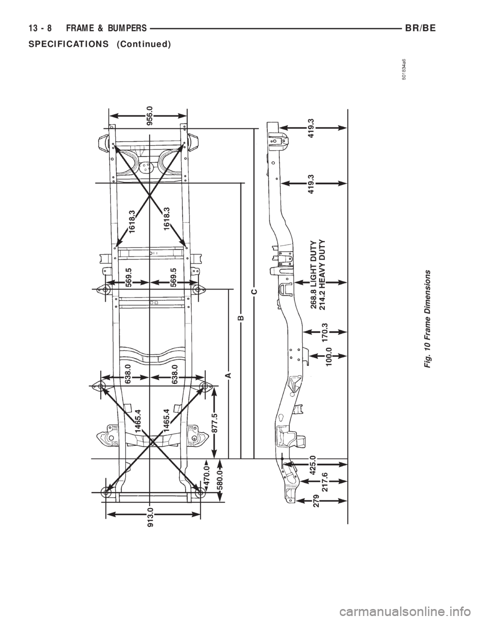
Fig. 10 Frame Dimensions
13 - 8 FRAME & BUMPERSBR/BE
SPECIFICATIONS (Continued)
Page 1484 of 2889
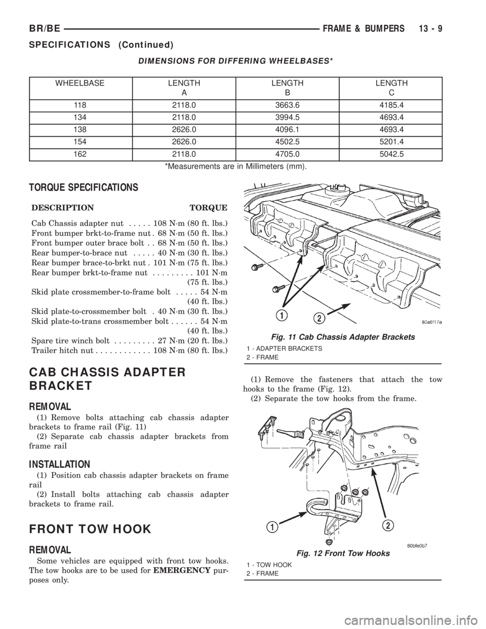
DIMENSIONS FOR DIFFERING WHEELBASES*
WHEELBASE LENGTH
ALENGTH
BLENGTH
C
118 2118.0 3663.6 4185.4
134 2118.0 3994.5 4693.4
138 2626.0 4096.1 4693.4
154 2626.0 4502.5 5201.4
162 2118.0 4705.0 5042.5
*Measurements are in Millimeters (mm).
TORQUE SPECIFICATIONS
DESCRIPTION TORQUE
Cab Chassis adapter nut..... 108N´m(80ft.lbs.)
Front bumper brkt-to-frame nut . 68 N´m (50 ft. lbs.)
Front bumper outer brace bolt . . 68 N´m (50 ft. lbs.)
Rear bumper-to-brace nut..... 40N´m(30ft.lbs.)
Rear bumper brace-to-brkt nut . 101 N´m (75 ft. lbs.)
Rear bumper brkt-to-frame nut......... 101N´m
(75 ft. lbs.)
Skid plate crossmember-to-frame bolt..... 54N´m
(40 ft. lbs.)
Skid plate-to-crossmember bolt . 40 N´m (30 ft. lbs.)
Skid plate-to-trans crossmember bolt...... 54N´m
(40 ft. lbs.)
Spare tire winch bolt......... 27N´m(20ft.lbs.)
Trailer hitch nut............ 108N´m(80ft.lbs.)
CAB CHASSIS ADAPTER
BRACKET
REMOVAL
(1) Remove bolts attaching cab chassis adapter
brackets to frame rail (Fig. 11)
(2) Separate cab chassis adapter brackets from
frame rail
INSTALLATION
(1) Position cab chassis adapter brackets on frame
rail
(2) Install bolts attaching cab chassis adapter
brackets to frame rail.
FRONT TOW HOOK
REMOVAL
Some vehicles are equipped with front tow hooks.
The tow hooks are to be used forEMERGENCYpur-
poses only.(1) Remove the fasteners that attach the tow
hooks to the frame (Fig. 12).
(2) Separate the tow hooks from the frame.
Fig. 11 Cab Chassis Adapter Brackets
1 - ADAPTER BRACKETS
2 - FRAME
Fig. 12 Front Tow Hooks
1 - TOW HOOK
2 - FRAME
BR/BEFRAME & BUMPERS 13 - 9
SPECIFICATIONS (Continued)
Page 1821 of 2889
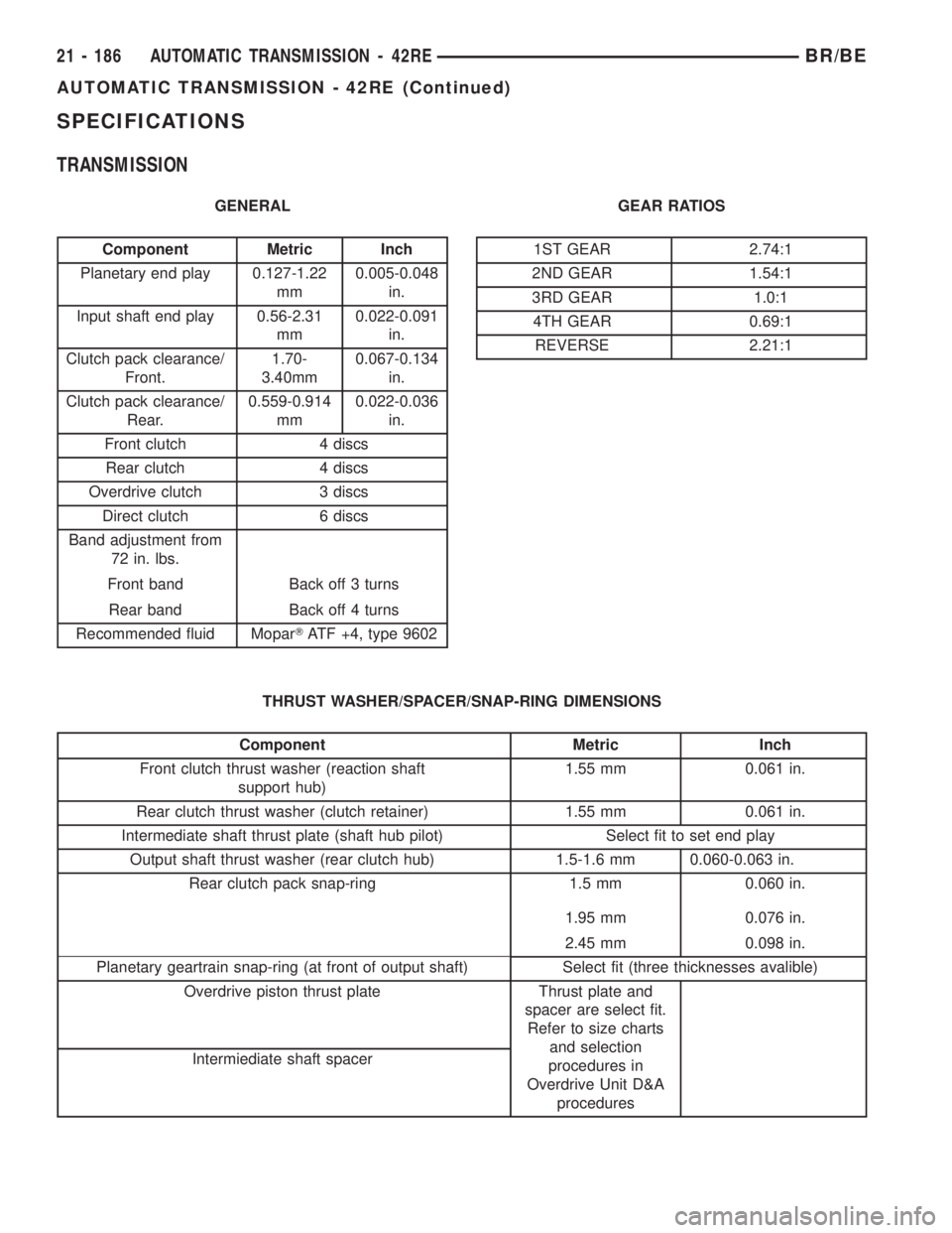
SPECIFICATIONS
TRANSMISSION
GENERAL
Component Metric Inch
Planetary end play 0.127-1.22
mm0.005-0.048
in.
Input shaft end play 0.56-2.31
mm0.022-0.091
in.
Clutch pack clearance/
Front.1.70-
3.40mm0.067-0.134
in.
Clutch pack clearance/
Rear.0.559-0.914
mm0.022-0.036
in.
Front clutch 4 discs
Rear clutch 4 discs
Overdrive clutch 3 discs
Direct clutch 6 discs
Band adjustment from
72 in. lbs.
Front band Back off 3 turns
Rear band Back off 4 turns
Recommended fluid MoparTATF +4, type 9602GEAR RATIOS1ST GEAR 2.74:1
2ND GEAR 1.54:1
3RD GEAR 1.0:1
4TH GEAR 0.69:1
REVERSE 2.21:1
THRUST WASHER/SPACER/SNAP-RING DIMENSIONS
Component Metric Inch
Front clutch thrust washer (reaction shaft
support hub)1.55 mm 0.061 in.
Rear clutch thrust washer (clutch retainer) 1.55 mm 0.061 in.
Intermediate shaft thrust plate (shaft hub pilot) Select fit to set end play
Output shaft thrust washer (rear clutch hub) 1.5-1.6 mm 0.060-0.063 in.
Rear clutch pack snap-ring 1.5 mm 0.060 in.
1.95 mm 0.076 in.
2.45 mm 0.098 in.
Planetary geartrain snap-ring (at front of output shaft) Select fit (three thicknesses avalible)
Overdrive piston thrust plate Thrust plate and
spacer are select fit.
Refer to size charts
and selection
procedures in
Overdrive Unit D&A
procedures Intermiediate shaft spacer
21 - 186 AUTOMATIC TRANSMISSION - 42REBR/BE
AUTOMATIC TRANSMISSION - 42RE (Continued)