2001 DODGE RAM crankshaft sensor
[x] Cancel search: crankshaft sensorPage 540 of 2889

SPARK PLUG CABLE RESISTANCE
MINIMUM MAXIMUM
250 Ohms Per Inch 1000 Ohms Per Inch
3000 Ohms Per Foot 12,000 Ohms Per Foot
SPARK PLUGS
ENGINE PLUG TYPE ELECTRODE GAP
3.9L V-6 RC12LC4 1.01 mm (.040 in.)
5.2L/5.9L V-8 RC12LC4 1.01 mm (.040 in.)
8.0L V-10 QC9MC4 1.14 mm (.045 in.)
IGNITION COIL RESISTANCEÐ3.9L/5.2L/5.9L ENGINES
COIL MANUFACTURERPRIMARY RESISTANCE
21-27ÉC (70-80ÉF)SECONDARY RESISTANCE 21-27ÉC
(70-80ÉF)
Diamond 0.97 - 1.18 Ohms 11,300 - 15,300 Ohms
Toyodenso 0.95 - 1.20 Ohms 11,300 - 13,300 Ohms
IGNITION COIL RESISTANCEÐ8.0L V-10
ENGINE
Primary Resistance: 0.53-0.65 Ohms. Test across the
primary connector. Refer to text for test procedures.
Secondary Resistance: 10.9-14.7K Ohms. Test
across the individual coil towers. Refer to text for test
procedures.
IGNITION TIMING
Ignition timing is not adjustable on any engine.
AUTOMATIC SHUT DOWN
RELAY
DESCRIPTION - PCM OUTPUT
The 5±pin, 12±volt, Automatic Shutdown (ASD)
relay is located in the Power Distribution Center
(PDC). Refer to label on PDC cover for relay location.
OPERATION - PCM OUTPUT
The ASD relay supplies battery voltage (12+ volts)
to the fuel injectors and ignition coil(s). With certain
emissions packages it also supplies 12±volts to the
oxygen sensor heating elements.
The ground circuit for the coil within the ASD
relay is controlled by the Powertrain Control Module
(PCM). The PCM operates the ASD relay by switch-
ing its ground circuit on and off.The ASD relay will be shut±down, meaning the
12±volt power supply to the ASD relay will be de-ac-
tivated by the PCM if:
²the ignition key is left in the ON position. This
is if the engine has not been running for approxi-
mately 1.8 seconds.
²there is a crankshaft position sensor signal to
the PCM that is lower than pre-determined values.
OPERATION - ASD SENSE - PCM INPUT
A 12 volt signal at this input indicates to the PCM
that the ASD has been activated. The relay is used to
connect the oxygen sensor heater element, ignition
coil and fuel injectors to 12 volt + power supply.
This input is used only to sense that the ASD relay
is energized. If the Powertrain Control Module
(PCM) does not see 12 volts at this input when the
ASD should be activated, it will set a Diagnostic
Trouble Code (DTC).
DIAGNOSIS AND TESTING - ASD AND FUEL
PUMP RELAYS
The following description of operation and
tests apply only to the Automatic Shutdown
(ASD) and fuel pump relays. The terminals on the
bottom of each relay are numbered. Two different
types of relays may be used, (Fig. 1) or (Fig. 2).
²Terminal number 30 is connected to battery volt-
age. For both the ASD and fuel pump relays, termi-
nal 30 is connected to battery voltage at all times.
BR/BEIGNITION CONTROL 8I - 3
IGNITION CONTROL (Continued)
Page 542 of 2889

INSTALLATION
The ASD relay is located in the Power Distribution
Center (PDC) (Fig. 3). Refer to label on PDC cover
for relay location.
(1) Install relay to PDC.
(2) Install cover to PDC.
CAMSHAFT POSITION
SENSOR
DESCRIPTION - DIESEL
The three-wire Camshaft Position Sensor (CMP) is
located below the fuel injection pump (Fig. 4). It is
attached to the back of the timing gear cover hous-
ing.
DESCRIPTION - 3.9L/5.2L/5.9L
The Camshaft Position (CMP) sensor is located in
the distributor.
DESCRIPTION - 8.0L
The Camshaft Position (CMP) sensor is located on
the timing chain case/cover on the left-front side of
the engine (Fig. 5).
OPERATION - DIESEL
The Camshaft Position Sensor (CMP) performs
multiple functions. One function is to detect engine
speed (rpm). Another function is to relate crankshaft
position and Top Dead Center (TDC) of the number 1
cylinder. Because the CMP is now used to relate
crankshaft position,the Crankshaft Position Sen-
sor (CKP) is no longer used.The CMP (Fig. 6) contains a hall effect device
called a sync signal generator to generate a sync sig-
nal.
The CMP uses three wires (circuits) for operation.
One wire supplies a 5±volt signal from the Engine
Control Module (ECM). Another wire supplies a sen-
sor ground. The third wire supplies a signal back to
the ECM relating engine speed and crankshaft posi-
tion.
Fig. 3 Power Distribution Center (PDC)
1 - POWER DISTRIBUTION CENTER (PDC)
Fig. 4 Camshaft Position Sensor (CMP) Location
1 - CAMSHAFT POSITION SENSOR (CMP)
2 - BOTTOM OF FUEL INJECTION PUMP
Fig. 5 CMP Sensor LocationÐ8.0L V-10 Engine
1 - CAMSHAFT POSITION SENSOR
2 - MOUNTING BOLT
3 - TIMING CHAIN CASE/COVER
BR/BEIGNITION CONTROL 8I - 5
AUTOMATIC SHUT DOWN RELAY (Continued)
Page 543 of 2889

The sensor detects machined notches on the rear
face of the camshaft drive gear (Fig. 7) to sense
engine speed.The CMP also detects an area on the camshaft
drive gear that has no notch (Fig. 7). When the sen-
sor passes this area, it tells the Engine Control Mod-
ule (ECM) that Top Dead Center (TDC) of the
number 1 cylinder is occurring. The ECM will then
adjust fuel timing accordingly.
As the tip of the sensor passes the notches, the
interruption of magnetic field causes voltage changes
from 5 volts to 0 volts.
OPERATION - 3.9L/5.2L/5.9L
The sensor contains a hall effect device called a
sync signal generator to generate a fuel sync signal.
This sync signal generator detects a rotating pulse
ring (shutter) on the distributor shaft. The pulse ring
rotates 180 degrees through the sync signal genera-
tor. Its signal is used in conjunction with the Crank-
shaft Position (CKP) sensor to differentiate between
fuel injection and spark events. It is also used to syn-
chronize the fuel injectors with their respective cylin-
ders.
When the leading edge of the pulse ring (shutter)
enters the sync signal generator, the following occurs:
The interruption of magnetic field causes the voltage
to switch high resulting in a sync signal of approxi-
mately 5 volts.
When the trailing edge of the pulse ring (shutter)
leaves the sync signal generator, the following occurs:
The change of the magnetic field causes the sync sig-
nal voltage to switch low to 0 volts.
OPERATION - 8.0L
The CMP sensor is used in conjunction with the
crankshaft position sensor to differentiate between
fuel injection and spark events. It is also used to syn-
chronize the fuel injectors with their respective cylin-
ders. The sensor generates electrical pulses. These
pulses (signals) are sent to the Powertrain Control
Module (PCM). The PCM will then determine crank-
shaft position from both the camshaft position sensor
and crankshaft position sensor.
A low and high area are machined into the cam-
shaft drive gear (Fig. 8). The sensor is positioned in
the timing gear cover so that a small air gap (Fig. 8)
exists between the face of sensor and the high
machined area of cam gear.
When the cam gear is rotating, the sensor will
detect the machined low area. Input voltage from the
sensor to the PCM will then switch from a low
(approximately 0.3 volts) to a high (approximately 5
volts). When the sensor detects the high machined
area, the input voltage switches back low to approx-
imately 0.3 volts.
Fig. 6 Camshaft Position Sensor (CMP)
1 - GEAR HOUSING
2 - O-RING
3 - CMP SENSOR
4 - CMP HEX HEAD BOLT
Fig. 7 Notches at Rear Of Camshaft Drive Gear
1 - CAMSHAFT DRIVE GEAR
2 - NOTCHES
3 - CAMSHAFT POSITION SENSOR (CKP)
4 - NO NOTCH
8I - 6 IGNITION CONTROLBR/BE
CAMSHAFT POSITION SENSOR (Continued)
Page 548 of 2889

OPERATION
The camshaft position sensor provides fuel injec-
tion synchronization and cylinder identification.
The distributor does not have built in centrifugal
or vacuum assisted advance. Base ignition timing
and all timing advance is controlled by the Power-
train Control Module (PCM). Because ignition timing
is controlled by the PCM,base ignition timing is
not adjustable.
The distributor is held to the engine in the conven-
tional method using a holddown clamp and bolt.
Although the distributor can be rotated, it will
have no effect on ignition timing.
All distributors contain an internal oil seal that
prevents oil from entering the distributor housing.
The seal is not serviceable.
REMOVAL
CAUTION: Base ignition timing is not adjustable on
any engine. Distributors do not have built in centrif-
ugal or vacuum assisted advance. Base ignition
timing and timing advance are controlled by the
Powertrain Control Module (PCM). Because a con-
ventional timing light can not be used to adjust dis-
tributor position after installation, note position of
distributor before removal.
(1) Remove air cleaner assembly.
(2) Disconnect negative cable from battery.
(3) Remove distributor cap from distributor (two
screws).
(4) Mark the position of distributor housing in
relationship to engine or dash panel. This is done to
aid in installation.(5) Before distributor is removed, the number one
cylinder must be brought to the Top Dead Center
(TDC) firing position.
(6) Attach a socket to the Crankshaft Vibration
Damper mounting bolt.
(7) Slowly rotate engine clockwise, as viewed from
front, until indicating mark on crankshaft vibration
damper is aligned to 0 degree (TDC) mark on timing
chain cover (Fig. 18).
(8) The distributor rotor should now be aligned to
the CYL. NO. 1 alignment mark (stamped) into the
camshaft position sensor (Fig. 19). If not, rotate the
crankshaft through another complete 360 degree
turn. Note the position of the number one cylinder
spark plug cable (on the cap) in relation to rotor.
Rotor should now be aligned to this position.
(9) Disconnect camshaft position sensor wiring
harness from main engine wiring harness.
(10) Remove distributor rotor from distributor
shaft.
(11) Remove distributor holddown clamp bolt and
clamp (Fig. 20). Remove distributor from vehicle.
CAUTION: Do not crank engine with distributor
removed. Distributor/crankshaft relationship will be
lost.
INSTALLATION
If engine has been cranked while distributor is
removed, establish the relationship between distribu-
tor shaft and number one piston position as follows:
Rotate crankshaft in a clockwise direction, as
viewed from front, until number one cylinder piston
is at top of compression stroke (compression should
be felt on finger with number one spark plug
Fig. 17 Distributor and Camshaft Position Sensor
1 - SYNC SIGNAL GENERATOR
2 - CAMSHAFT POSITION SENSOR
3 - PULSE RING
4 - DISTRIBUTOR ASSEMBLY
Fig. 18 Damper-To-Cover Alignment MarksÐTypical
1 - ALIGNMENT MARK
2 - TIMING CHAIN COVER MARKS
3 - CRANKSHAFT VIBRATION DAMPER
BR/BEIGNITION CONTROL 8I - 11
DISTRIBUTOR (Continued)
Page 551 of 2889

filled coils. The rear coil pack contains two indepen-
dent epoxy filled coils.
OPERATION - 3.9L/5.2L/5.9L
The Powertrain Control Module (PCM) opens and
closes the ignition coil ground circuit for ignition coil
operation.
Battery voltage is supplied to the ignition coil pos-
itive terminal from the ASD relay. If the PCM does
not see a signal from the crankshaft and camshaft
sensors (indicating the ignition key is ON but the
engine is not running), it will shut down the ASD cir-
cuit.
Base ignition timing is not adjustable on any
engine.By controlling the coil ground circuit, the
PCM is able to set the base timing and adjust the
ignition timing advance. This is done to meet chang-
ing engine operating conditions.
OPERATION - 8.0L
When one of the 5 independent coils discharges, it
fires two paired cylinders at the same time (one cyl-
inder on compression stroke and the other cylinder
on exhaust stroke).
Coil firing is paired together on cylinders:
²Number 5 and 10
²Number 9 and 8
²Number 1 and 6
²Number 7 and 4
²Number 3 and 2
The ignition system is controlled by the Powertrain
Control Module (PCM) on all engines.
Battery voltage is supplied to all of the ignition
coils positive terminals from the ASD relay. If the
PCM does not see a signal from the crankshaft and
camshaft sensors (indicating the ignition key is ONbut the engine is not running), it will shut down the
ASD circuit.
Base ignition timing is not adjustable on the
8.0L V-10 engine.By controlling the coil ground cir-
cuit, the PCM is able to set the base timing and
adjust the ignition timing advance. This is done to
meet changing engine operating conditions.
The PCM adjusts ignition timing based on inputs it
receives from:
²The engine coolant temperature sensor
²The crankshaft position sensor (engine speed)
²The manifold absolute pressure (MAP) sensor
²The throttle position sensor
²Transmission gear selection
REMOVAL - 3.9L/5.2L/5.9L
The ignition coil is an epoxy filled type. If the coil
is replaced, it must be replaced with the same type.
3.9L V-6 or 5.2/5.9L V-8 LDC-Gas Engines: The coil
is mounted to a bracket that is bolted to the front of
the right engine cylinder head (Fig. 25). This bracket
is mounted on top of the automatic belt tensioner
bracket using common bolts.
5.9L V-8 HDC-Gas Engine: The coil is mounted to
a bracket that is bolted to the air injection pump
(AIR pump) mounting bracket (Fig. 26).
(1) Disconnect the primary wiring from the igni-
tion coil.
(2) Disconnect the secondary spark plug cable from
the ignition coil.
Fig. 24 Ignition Coil PacksÐ8.0L V-10 Engine
Fig. 25 Ignition CoilÐ3.9L V-6 or 5.2/5.9L V-8
LDC-Gas Engines
1 - ACCESSORY DRIVE BELT TENSIONER
2 - COIL CONNECTOR
3 - IGNITION COIL
4 - COIL MOUNTING BOLTS
8I - 14 IGNITION CONTROLBR/BE
IGNITION COIL (Continued)
Page 590 of 2889

ment cluster. The tachometer consists of a movable
gauge needle or pointer controlled by the instrument
cluster circuitry and a fixed 210 degree scale on the
gauge dial face that reads left-to-right either from 0
to 6 for gasoline engines, or from 0 to 4 for diesel
engines. The text ªRPM X 1000º imprinted on the
cluster overlay directly below the hub of the tachom-
eter needle identifies that each number on the
tachometer scale is to be multiplied times 1000 rpm.
The gauge scale of the gasoline engine tachometer is
red lined at 5000 rpm, while the diesel engine
tachometer is red lined at 3375 rpm. The diesel
engine tachometer also includes text that specifies
ªDIESEL FUEL ONLYº located just above the hub of
the tachometer needle. The tachometer graphics are
white and red against a black field, making them
clearly visible within the instrument cluster in day-
light. When illuminated from behind by the panel
lamps dimmer controlled cluster illumination lighting
with the exterior lamps turned On, the white graph-
ics appear blue-green, while the red graphics still
appear red. The orange gauge needle is internally
illuminated. Gauge illumination is provided by
replaceable incandescent bulb and bulb holder units
located on the instrument cluster electronic circuit
board. The tachometer is serviced as a unit with the
instrument cluster.
OPERATION
The tachometer gives an indication to the vehicle
operator of the engine speed. This gauge is controlled
by the instrument cluster circuit board based upon
the cluster programming and electronic messages
received by the cluster from the Powertrain Control
Module (PCM) over the Chrysler Collision Detection
(CCD) data bus. The tachometer is an air core mag-
netic unit that receives battery current on the instru-
ment cluster electronic circuit board through the
fused ignition switch output (st-run) circuit whenever
the ignition switch is in the On or Start positions.
The cluster is programmed to move the gauge needle
back to the low end of the scale after the ignition
switch is turned to the Off position. The instrument
cluster circuitry controls the gauge needle position
and provides the following features:
²Message Failure- If the cluster fails to receive
an engine speed message, it will hold the gauge nee-
dle at the last indication for about four seconds, or
until the ignition switch is turned to the Off position,
whichever occurs first. If a new engine speed mes-
sage is not received after about four seconds, the
gauge needle will return to the far left (low) end of
the scale.
²Actuator Test- Each time the cluster is put
through the actuator test, the gauge needle will be
swept to several calibration points on the gauge scalein a prescribed sequence in order to confirm the func-
tionality of the gauge and the cluster control cir-
cuitry.
The PCM continually monitors the crankshaft posi-
tion sensor to determine the engine speed, then
sends the proper engine speed messages to the
instrument cluster. For further diagnosis of the
tachometer or the instrument cluster circuitry that
controls the gauge, (Refer to 8 - ELECTRICAL/IN-
STRUMENT CLUSTER - DIAGNOSIS AND TEST-
ING). For proper diagnosis of the crankshaft position
sensor, the PCM, the CCD data bus, or the message
inputs to the instrument cluster that control the
tachometer, a DRBIIItscan tool is required. Refer to
the appropriate diagnostic information.
TRANSMISSION OVERTEMP
INDICATOR
DESCRIPTION
A transmission over-temperature indicator lamp is
standard equipment on all instrument clusters. How-
ever, on vehicles not equipped with the optional auto-
matic transmission, this indicator is electronically
disabled. The transmission over-temperature indica-
tor is located near the lower edge of the instrument
cluster overlay, to the left of center. The transmission
over-temperature indicator consists of a stencilled
cutout of the words ªTRANS TEMPº in the opaque
layer of the instrument cluster overlay. The dark
outer layer of the overlay prevents the indicator from
being clearly visible when it is not illuminated. A red
lens behind the cutout in the opaque layer of the
overlay causes the ªTRANS TEMPº text to appear in
red through the translucent outer layer of the over-
lay when the indicator is illuminated from behind by
a Light Emitting Diode (LED) soldered onto the
instrument cluster electronic circuit board. The
transmission over-temperature indicator is serviced
as a unit with the instrument cluster.
OPERATION
The transmission over-temperature indicator gives
an indication to the vehicle operator when the trans-
mission fluid temperature is excessive, which may
lead to accelerated transmission component wear or
failure. This indicator is controlled by a transistor on
the instrument cluster circuit board based upon the
cluster programming and electronic messages
received by the cluster from the Powertrain Control
Module (PCM) over the Chrysler Collision Detection
(CCD) data bus. The transmission over-temperature
indicator Light Emitting Diode (LED) receives bat-
tery current on the instrument cluster electronic cir-
cuit board through the fused ignition switch output
BR/BEINSTRUMENT CLUSTER 8J - 31
TACHOMETER (Continued)
Page 756 of 2889

8W-02 COMPONENT INDEX
Component Page
4WD Switch.......................... 8W-31
A/C Compressor Clutch Relay............ 8W-42
A/C Compressor Clutch................. 8W-42
A/C-Heater Control.................... 8W-42
A/C Heater Temperature Select........... 8W-42
A/C High Pressure Switch............... 8W-42
A/C Low Pressure Switch................ 8W-42
Accelerator Pedal Position Sensor......... 8W-30
Aftermarket Center High Mounted
Stop Lamp......................... 8W-51
Aftermarket Trailer Tow Connector........ 8W-54
Airbag Control Module.................. 8W-43
Ambient Temperature Sensor............ 8W-49
Ash Receiver Lamp.................... 8W-44
Automatic Day/Night Mirror............. 8W-49
Automatic Shut Down Relay............. 8W-30
Auxiliary Battery...................... 8W-20
Back-Up Lamp Switch.................. 8W-51
Back-Up Lamps....................... 8W-51
Battery Temperature Sensor............. 8W-30
Battery............................. 8W-20
Blend Door Actuator................... 8W-42
Blower Motor Relay.................... 8W-42
Blower Motor Resistor Block............. 8W-42
Blower Motor......................... 8W-42
Brake Lamp Switch.................... 8W-51
Brake Pressure Switch............... 8W-34, 35
Bypass Jumper....................... 8W-21
Camshaft Position Sensor............... 8W-30
Capacitor......................... 8W-10, 30
Cargo Lamps......................... 8W-44
Center High Mounted Stop Lamps........ 8W-51
Center Identification Lamp.............. 8W-50
Central Timer Module.................. 8W-45
Cigar Lighter......................... 8W-41
Circuit Breakers...................... 8W-12
Clockspring.................. 8W-33, 41, 43, 47
Clutch Pedal Position Switch............. 8W-21
Combination Flasher................... 8W-52
Controller Antilock Brake............ 8W-34, 35
Crankshaft Position Sensor.............. 8W-30
Cummins Bus........................ 8W-18
Cup Holder Lamp..................... 8W-44
Cylinder Lock Switches................ 8W-39
Data Link Connector................... 8W-18
Daytime Running Lamp Module.......... 8W-50
Dome Lamp.......................... 8W-44
Door Ajar Switches.................... 8W-45
Door Lock Motors..................... 8W-61
Door Window/Lock Switches.......... 8W-60, 61
Driver Airbag......................... 8W-43
Duty Cycle EVAP/Purge Solenoid......... 8W-30Component Page
Electric Brake Provision................ 8W-54
Engine Control Module.............. 8W-30, 70
Engine Coolant Temperature Sensor....... 8W-30
Engine Oil Pressure Sensor.............. 8W-30
Engine Starter Motor Relay.............. 8W-21
Engine Starter Motor................... 8W-21
Fender Lamp......................... 8W-51
Fog Lamp Indicator.................... 8W-50
Fog Lamp Relay....................... 8W-50
Fog Lamp............................ 8W-50
Fuel Heater Relay..................... 8W-30
Fuel Heater.......................... 8W-30
Fuel Injection Pump................... 8W-30
Fuel Injectors......................... 8W-30
Fuel Transfer Pump.................... 8W-30
Fuses (JB)........................... 8W-12
Fuses (PDC).......................... 8W-10
Fusible Link....................... 8W-20, 30
Generator............................ 8W-20
Glove Box Lamp And Switch............. 8W-44
Grounds............................. 8W-15
Headlamp Beam Select Switch........... 8W-50
Headlamp Switch...................... 8W-50
Headlamp........................... 8W-50
Heated Mirror Relay................... 8W-62
Heated Mirror Switch.................. 8W-62
Heated Seat Cushions.................. 8W-63
Heated Seat Relay..................... 8W-12
Heated Seat Switches.................. 8W-63
High Beam Indicator................... 8W-40
High Note Horn....................... 8W-41
Horn Relay.......................... 8W-41
Horn Switch.......................... 8W-41
Idle Air Control Motor.................. 8W-30
Ignition Coil 4-Pack.................... 8W-30
Ignition Coil 6-Pack.................... 8W-30
Ignition Coil.......................... 8W-30
Ignition Switch....................... 8W-10
Instrument Cluster.................... 8W-40
Intake Air Heater Relays................ 8W-30
Intake Air Heater..................... 8W-30
Intake Air Temperature Sensor........... 8W-30
Intermittent Wiper Switch............... 8W-53
Joint Connectors . . 8W-10, 12, 15, 30, 31, 34, 35, 40,
44, 45, 51, 53, 70
Junction Block........................ 8W-12
Leak Detection Pump.................. 8W-30
License Lamp......................... 8W-51
Low Note Horn....................... 8W-41
Lumbar Motors....................... 8W-63
Manifold Absolute Pressure Sensor........ 8W-30
Manifold Air Pressure Sensor............ 8W-30
BR/BE8W-02 COMPONENT INDEX 8W - 02 - 1
Page 838 of 2889
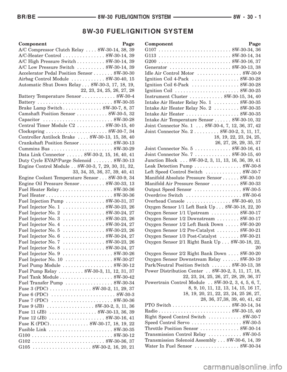
8W-30 FUEL/IGNITION SYSTEM
Component Page
A/C Compressor Clutch Relay.... 8W-30-14, 38, 39
A/C-Heater Control............... 8W-30-14, 39
A/C High Pressure Switch.......... 8W-30-14, 39
A/C Low Pressure Switch.......... 8W-30-14, 39
Accelerator Pedal Position Sensor....... 8W-30-30
Airbag Control Module............ 8W-30-40, 15
Automatic Shut Down Relay . . . 8W-30-3, 17, 18, 19,
22, 23, 24, 25, 26, 27, 28
Battery Temperature Sensor............ 8W-30-4
Battery........................... 8W-30-35
Brake Lamp Switch.............. 8W-30-7, 8, 37
Camshaft Position Sensor........... 8W-30-5, 32
Capacitor......................... 8W-30-28
Central Timer Module C2.......... 8W-30-15, 40
Clockspring...................... 8W-30-7, 34
Controller Antilock Brake.... 8W-30-13, 15, 38, 40
Crankshaft Position Sensor............ 8W-30-13
Cummins Bus...................... 8W-30-29
Data Link Connector...... 8W-30-2, 15, 16, 40, 41
Duty Cycle EVAP/Purge Solenoid....... 8W-30-13
Engine Control Module . . 8W-30-3, 7, 29, 30, 31, 32,
33, 34, 35, 36, 37, 39, 40, 41
Engine Coolant Temperature Sensor . . . 8W-30-9, 34
Engine Oil Pressure Sensor......... 8W-30-33, 13
Fuel Heater Relay................... 8W-30-36
Fuel Heater........................ 8W-30-36
Fuel Injection Pump.............. 8W-30-31, 37
Fuel Injector No. 1............... 8W-30-23, 26
Fuel Injector No. 2............... 8W-30-24, 27
Fuel Injector No. 3............... 8W-30-23, 26
Fuel Injector No. 4............... 8W-30-24, 27
Fuel Injector No. 5............... 8W-30-23, 26
Fuel Injector No. 6............... 8W-30-24, 27
Fuel Injector No. 7............... 8W-30-23, 26
Fuel Injector No. 8............... 8W-30-24, 27
Fuel Injector No. 9.................. 8W-30-26
Fuel Injector No. 10................. 8W-30-27
Fuel Pump Module.................. 8W-30-12
Fuel Pump Relay......... 8W-30-3, 11, 12, 31, 37
Fuel Tank Module................... 8W-30-42
Fuel Transfer Pump................. 8W-30-34
Fuse 3 (PDC)............... 8W-30-2, 11, 29, 37
Fuse 6 (PDC)....................... 8W-30-3
Fuse 7 (PDC)...................... 8W-30-36
Fuse 9 (JB)................. 8W-30-2, 3, 11, 36
Fuse 11 (JB)................. 8W-30-13, 36, 39
Fuse 12 (JB).................... 8W-30-16, 41
Fuse K (PDC).............. 8W-30-17, 18, 19, 22
Fusible Link....................... 8W-30-35
G100............................. 8W-30-12
G102.......................... 8W-30-36, 37
G105..................... 8W-30-2, 16, 20, 21Component Page
G107.......................... 8W-30-34, 36
G113 .......................... 8W-30-14, 34
G200.......................... 8W-30-16, 37
Generator...................... 8W-30-13, 38
Idle Air Control Motor................ 8W-30-9
Ignition Coil 4-Pack................. 8W-30-28
Ignition Coil 6-Pack................. 8W-30-28
Ignition Coil....................... 8W-30-25
Instrument Cluster............ 8W-30-15, 34, 40
Intake Air Heater Relay No. 1......... 8W-30-35
Intake Air Heater Relay No. 2......... 8W-30-35
Intake Air Heater................... 8W-30-35
Intake Air Temperature Sensor...... 8W-30-10, 32
Joint Connector No. 1 . . . 8W-30-4, 7, 12, 36, 37, 42
Joint Connector No. 2......... 8W-30-2, 3, 11, 17,
18, 19, 22, 23, 24, 25,
26, 27, 28, 29, 35, 37
Joint Connector No. 5............. 8W-30-16, 41
Joint Connector No. 7............. 8W-30-15, 40
Junction Block . . . 8W-30-2, 3, 11, 13, 16, 36, 39, 41
Leak Detection Pump................. 8W-30-8
Left Speed Control Switch............. 8W-30-7
Manifold Absolute Pressure Sensor...... 8W-30-10
Manifold Air Pressure Sensor.......... 8W-30-33
Output Speed Sensor................. 8W-30-5
Overdrive Switch.................... 8W-30-6
Overhead Console................ 8W-30-40, 15
Oxygen Sensor 1/1 Left Bank Up . . . 8W-30-18, 22, 20
Oxygen Sensor 1/1 Upstream.......... 8W-30-17
Oxygen Sensor 1/2 Downstream........ 8W-30-17
Oxygen Sensor 1/2 Left Bank Down..... 8W-30-20
Oxygen Sensor 1/2 Pre-Catalyst........ 8W-30-21
Oxygen Sensor 1/3 Post-Catalyst....... 8W-30-21
Oxygen Sensor 2/1 Right Bank Up . . . 8W-30-18, 22,
20
Oxygen Sensor 2/2 Right Bank Down.... 8W-30-20
Oxygen Sensor Downstream Relay...... 8W-30-19
Park/Neutral Position Switch....... 8W-30-13, 38
Power Distribution Center . . 8W-30-2, 3, 11, 17, 18,
22, 23, 24, 25, 26, 27, 28, 29, 36, 37
Powertrain Control Module . . 8W-30-2, 3, 4, 5, 6, 7,
8, 9, 10, 11, 12, 13, 14, 15, 16 17,
18, 19, 20, 21, 22, 23, 24, 25 26, 27,
28, 36, 37,38, 39, 40, 41, 42
PTO Switch..................... 8W-30-14, 34
Radio.......................... 8W-30-15, 40
Right Speed Control Switch............ 8W-30-7
Speed Control Servo.................. 8W-30-5
Throttle Position Sensor.............. 8W-30-14
Transmission Control Relay............ 8W-30-5
Transmission Solenoid Assembly . . . 8W-30-6, 14, 39
Water In Fuel Sensor................ 8W-30-34
BR/BE8W-30 FUEL/IGNITION SYSTEM 8W - 30 - 1