Although the generators appear the same exter-
nally, different generators with different output rat-
ings are used on this vehicle. Be certain that the
replacement generator has the same output rating
and part number as the original unit. Refer to Gen-
erator Ratings in the Specifications section at the
back of this group for amperage ratings and part
numbers.
Noise emitting from the generator may be caused
by: worn, loose or defective bearings; a loose or defec-
tive drive pulley; incorrect, worn, damaged or misad-
justed fan drive belt; loose mounting bolts; a
misaligned drive pulley or a defective stator or diode.
REMOVAL
WARNING: DISCONNECT NEGATIVE CABLE FROM
BATTERY BEFORE REMOVING BATTERY OUTPUT
WIRE (B+ WIRE) FROM GENERATOR. FAILURE TO
DO SO CAN RESULT IN INJURY OR DAMAGE TO
ELECTRICAL SYSTEM.
(1) Disconnect negative battery cable at battery.
Diesel Engines: Disconnect both negative battery
cables at both batteries.
(2) Remove generator drive belt. Refer to 7, Cool-
ing System for procedure.
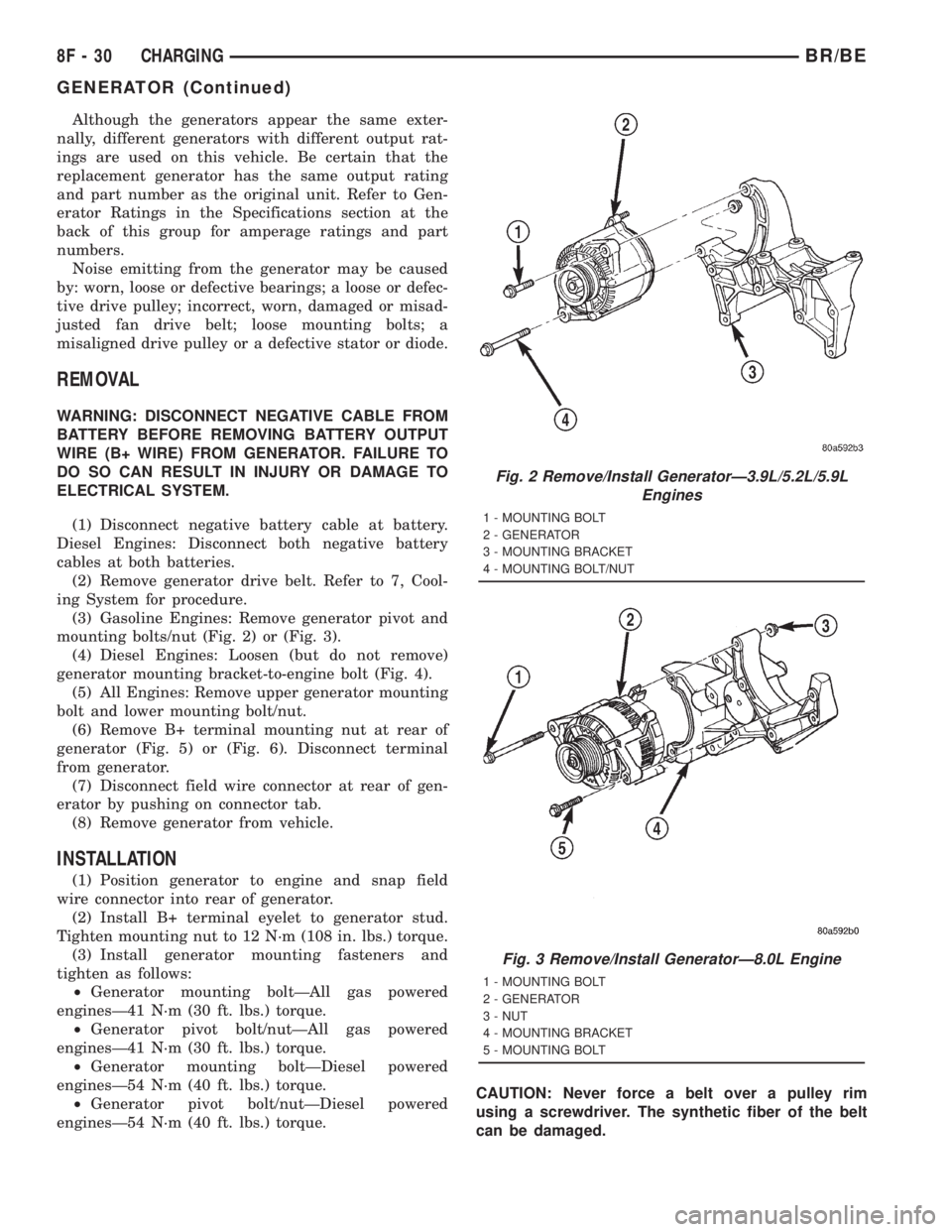
(3) Gasoline Engines: Remove generator pivot and
mounting bolts/nut (Fig. 2) or (Fig. 3).
(4) Diesel Engines: Loosen (but do not remove)
generator mounting bracket-to-engine bolt (Fig. 4).
(5) All Engines: Remove upper generator mounting
bolt and lower mounting bolt/nut.
(6) Remove B+ terminal mounting nut at rear of
generator (Fig. 5) or (Fig. 6). Disconnect terminal
from generator.
(7) Disconnect field wire connector at rear of gen-
erator by pushing on connector tab.
(8) Remove generator from vehicle.
INSTALLATION
(1) Position generator to engine and snap field
wire connector into rear of generator.
(2) Install B+ terminal eyelet to generator stud.
Tighten mounting nut to 12 N´m (108 in. lbs.) torque.
(3) Install generator mounting fasteners and
tighten as follows:
²Generator mounting boltÐAll gas powered
enginesÐ41 N´m (30 ft. lbs.) torque.
²Generator pivot bolt/nutÐAll gas powered
enginesÐ41 N´m (30 ft. lbs.) torque.
²Generator mounting boltÐDiesel powered
enginesÐ54 N´m (40 ft. lbs.) torque.
²Generator pivot bolt/nutÐDiesel powered
enginesÐ54 N´m (40 ft. lbs.) torque.CAUTION: Never force a belt over a pulley rim
using a screwdriver. The synthetic fiber of the belt
can be damaged.
Fig. 2 Remove/Install GeneratorÐ3.9L/5.2L/5.9L
Engines
1 - MOUNTING BOLT
2 - GENERATOR
3 - MOUNTING BRACKET
4 - MOUNTING BOLT/NUT
Fig. 3 Remove/Install GeneratorÐ8.0L Engine
1 - MOUNTING BOLT
2 - GENERATOR
3 - NUT
4 - MOUNTING BRACKET
5 - MOUNTING BOLT
8F - 30 CHARGINGBR/BE
GENERATOR (Continued)
CAUTION: The high-pressure fuel lines must be
clamped securely in place in the holders. The lines
cannot contact each other or other components. Do
not attempt to weld high-pressure fuel lines or to
repair lines that are damaged. Only use the recom-
mended lines when replacement of high-pressure
fuel line is necessary.
REMOVAL
High-pressure lines are used between the fuel
injection pump and the fuel injectors only. All high-
pressure fuel lines are of the same length and inside
diameter. Correct high-pressure fuel line usage and
installation is critical to smooth engine operation.
CAUTION: Refer to Cleaning Fuel System Parts.
(1) Disconnect both negative battery cables from
both batteries. Cover and isolate ends of cables.
(2) Thoroughly clean fuel lines at cylinder head
and injection pump ends.
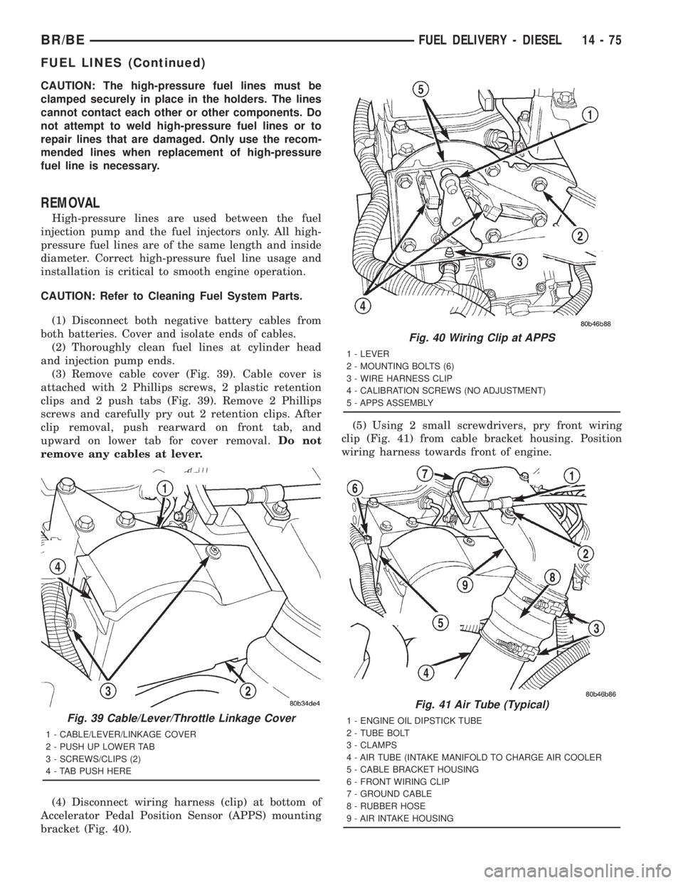
(3) Remove cable cover (Fig. 39). Cable cover is
attached with 2 Phillips screws, 2 plastic retention
clips and 2 push tabs (Fig. 39). Remove 2 Phillips
screws and carefully pry out 2 retention clips. After
clip removal, push rearward on front tab, and
upward on lower tab for cover removal.Do not
remove any cables at lever.
(4) Disconnect wiring harness (clip) at bottom of
Accelerator Pedal Position Sensor (APPS) mounting
bracket (Fig. 40).(5) Using 2 small screwdrivers, pry front wiring
clip (Fig. 41) from cable bracket housing. Position
wiring harness towards front of engine.
Fig. 39 Cable/Lever/Throttle Linkage Cover
1 - CABLE/LEVER/LINKAGE COVER
2 - PUSH UP LOWER TAB
3 - SCREWS/CLIPS (2)
4 - TAB PUSH HERE
Fig. 40 Wiring Clip at APPS
1 - LEVER
2 - MOUNTING BOLTS (6)
3 - WIRE HARNESS CLIP
4 - CALIBRATION SCREWS (NO ADJUSTMENT)
5 - APPS ASSEMBLY
Fig. 41 Air Tube (Typical)
1 - ENGINE OIL DIPSTICK TUBE
2 - TUBE BOLT
3 - CLAMPS
4 - AIR TUBE (INTAKE MANIFOLD TO CHARGE AIR COOLER
5 - CABLE BRACKET HOUSING
6 - FRONT WIRING CLIP
7 - GROUND CABLE
8 - RUBBER HOSE
9 - AIR INTAKE HOUSING
BR/BEFUEL DELIVERY - DIESEL 14 - 75
FUEL LINES (Continued)