2001 DODGE RAM air condition
[x] Cancel search: air conditionPage 32 of 2889
²Flush and replace engine coolant if it has been
30,000 miles (48 000 km) or 24 months since last
change.
²Inspect front wheel bearings. Clean and repack,
if required (4x4).
²Inspect engine air cleaner element, replace
as necessary (8.0L only).
*Requires Service Reminder Indicator Light. If so
equipped, these parts are to be replaced at the indi-
cated mileage or when the service reminder indicator
light remains on continuously with the key in the
ªONº position, whichever occurs first.
HEAVY DUTY SCHEDULE ªBº
Follow this schedule if the vehicle is usually oper-
ated under one or more of the following conditions.
²Frequent short trips driving less than 5 miles
(8km)
²Frequent driving in dusty conditions
²Frequent trailer towing
²Extensive idling
²More than 50% of the driving is at sustained
high speeds during hot weather, above 90ÉF (32ÉC)
3,000 Miles (5 000 km)
²Change engine oil.
²Replace engine oil filter.
²Lubricate tie rod ends every 3,000 miles (5 000
km).
6,000 Miles (10 000 km)
²Change engine oil.
²Replace engine oil filter.
²Lubricate tie rod ends every 3,000 miles (5 000
km).
²Inspect front wheel bearings (4x4).
9,000 Miles (14 000 km)
²Change engine oil.
²Replace engine oil filter.
²Lubricate tie rod ends every 3,000 miles (5 000
km).
²Inspect front wheel bearings (4x2).
12,000 Miles (19 000 km)
²Change engine oil.
²Replace engine oil filter.
²Inspect engine air cleaner element and air
pump filter, replace as necessary.
²Drain and refill automatic transmission fluid.
Replace filter and adjust bands.³
²Change rear axle fluid.
²Change front axle fluid (4x4).
²Inspect brake linings.
²Lubricate tie rod ends every 3,000 miles (5 000
km).
²Inspect front wheel bearings (4x4).
15,000 Miles (24 000 km)
²Change engine oil.
²Replace engine oil filter.
²Lubricate tie rod ends every 3,000 miles (5 000
km).
18,000 Miles (29 000 km)
²Change engine oil.
²Replace engine oil filter.
²Lubricate tie rod ends every 3,000 miles (5 000
km).
²Inspect front wheel bearings (4x4).
²Inspect front wheel bearings (4x2).
²Drain and refill transfer case fluid every 18,000
miles (4x4).
21,000 Miles (34 000 km)
²Change engine oil.
²Replace engine oil filter.
²Lubricate tie rod ends every 3,000 miles (5 000
km).
24,000 Miles (38 000 km)
²Change engine oil
²Replace engine oil filter.
²Replace engine air cleaner element and air
pump filter.
²Drain and refill automatic transmission fluid.
Replace filter and adjust bands.
²Change rear axle fluid.
²Change front axle fluid (4x4).
²Clean and lubricate crankcase inlet air filter
(5.9L).
²Inspect front wheel bearings. Clean and repack,
if required (4x2).
²Inspect brake linings.
²Lubricate tie rod ends every 3,000 miles (5 000
km).
²Inspect front wheel bearings (4x4).
27,000 Miles (43 000 km)
²Change engine oil.
²Replace engine oil filter.
²Lubricate tie rod ends every 3,000 miles (5 000
km).
²Inspect front wheel bearings (4x2).
30,000 Miles (48 000 km)
²Change engine oil.
²Replace engine oil filter.
²Lubricate tie rod ends every 3,000 miles (5 000
km).
²Inspect PCV valve, replace as necessary
(5.9L).
²Replace spark plugs.
²Inspect front wheel bearings (4x4).
BR/BELUBRICATION & MAINTENANCE 0 - 19
MAINTENANCE SCHEDULES (Continued)
Page 35 of 2889
99,000 Miles (156 000 km)
²Change engine oil.
²Replace engine oil filter.
²Lubricate tie rod ends every 3,000 miles (5 000
km).
²Inspect front wheel bearings (4x2).
102,000 Miles (163 000 km)
²Change engine oil.
²Replace engine oil filter.
²Lubricate tie rod ends every 3,000 miles (5 000
km).
²Inspect front wheel bearings (4x4).
105,000 Miles (168 000 km)
²Change engine oil.
²Replace engine oil filter.
²Lubricate tie rod ends every 3,000 miles (5 000
km).
108,000 Miles (173 000 km)
²Change engine oil.
²Replace engine oil filter.
²Inspect engine air cleaner element and air
pump filter, replace as necessary.
²Drain and refill automatic transmission fluid.
Replace filter and adjust bands.³
²Drain and refill transfer case fluid (4x4).
²Change rear axle fluid.
²Change front axle fluid (4x4).
²Inspect brake linings.
²Flush and replace engine coolant if it has been
30,000 miles (48 000 km) since last change.
²Lubricate tie rod ends every 3,000 miles (5 000
km).
²Inspect front wheel bearings (4x4).
²Inspect front wheel bearings (4x2).
*Requires Service Reminder Indicator Light. If so
equipped, these parts are to be replaced at the indi-
cated mileage or when the service reminder indicator
light remains on continuously with the key in the
ªONº position, whichever occurs first.
³Off-the-highway operation, trailer towing, snow
plowing, prolonged operation with heavy loading,
especially in hot weather require the more frequent
transmission service indicated witha³inSchedule
ªBº. Perform these services if you usually operate
your Ram Truck under these conditions.
Inspection and service should also be performed
anytime a malfunction is observed or suspected.
DESCRIPTION - MAINTENANCE SCHEDULES
Ð 24±VALVE CUMMINS TURBO DIESEL
There are two maintenance schedules that show
proper service for the vehicle.First is ScheduleªA.ºIt lists all the scheduled
maintenance to be performed under ªnormalº operat-
ing conditions.
Second is ScheduleªB.ºIt is a schedule for vehicles
that are operated under the conditions listed at the
beginning of that schedule.
Use the schedule that best describes the driving
conditions.
Where time and mileage are listed, follow the
interval that occurs first.
At Each Stop For Fuel
²Check engine oil level and add as required.
²Check windshield washer solvent and add if
required.
²Clean windshield and wiper blades as required.
²Drain water from fuel filter.
Once A Month
²Check tire pressure and look for unusual wear
or damage.
²Inspect battery and clean and tighten terminals
as required.
²Check fluid levels of coolant reservoir, brake
master cylinder, power steering, and transmission.
Add fluid as required.
²Check all lights and all other electrical items for
correct operation.
²Check Filter Mindery. Replace air cleaner
element if necessary.
²Inspect and clean wiper blades. Replace if
required.
At Each Oil Change
²Inspect exhaust system.
²Inspect brake hoses.
²Adjust rear brakes.
²Rotate the tires at each oil change interval
shown at 7, 5000 miles (12 000 km) on schedule ªAº
or every other interval shown at 7,500 miles (12 000
km) on schedule ªBº.
²Check engine coolant level, hoses, and clamps.
²Lubricate steering linkage.
²Drain crankcase breather canister (if equipped).
EMISSION CONTROL SYSTEM MAINTENANCE
The scheduled emission maintenance listed inbold
typeon the Maintenance Schedules, must be done at
the mileage specified to assure the continued proper
functioning of the emission control system. These,
and all other maintenance services included in this
manual, should be done to provide the best vehicle
performance and reliability. More frequent mainte-
nance may be needed for vehicles in severe operating
conditions such as dusty areas and very short trip
driving.
0 - 22 LUBRICATION & MAINTENANCEBR/BE
MAINTENANCE SCHEDULES (Continued)
Page 54 of 2889
(5) Install the steering knuckle on the lower ball
joint. Install the lower ball joint nut and tighten to:
²LD: 129 N´m (95 ft. lbs.)
²HD: 136 N´m (110 ft. lbs.)
(5) Install the lower ball joint cotter pin.
(6) Install the stabilizer bar link on the lower sus-
pension arm. Install the grommet, retainer and nut
and tighten to 37 N´m (27 ft. lbs.).
(7) Install the tie rod end on the steering knuckle
and tighten nut to 108 N´m (80 ft. lbs.). Install cotter
pin.
(8) Install the brake rotor and caliper assembly,
(Refer to 5 - BRAKES/HYDRAULIC/MECHANICAL/
ROTORS - INSTALLATION).
(9) Install the tire and wheel assembly, (Refer to
22 - TIRES/WHEELS/WHEELS - STANDARD PRO-
CEDURE).
(10) Remove the support and lower the vehicle.
(11) Tighten the suspension arm crossmember
nuts to 169 N´m (125 ft. lbs.).
SHOCK
DESCRIPTION
The top of the shocks mounts on frame brackets
using grommets. The bottom of the shock is bolted to
the lower suspension arms.
OPERATION
The shock absorbers dampen jounce and rebound
of the vehicle over various road conditions.
DIAGNOSIS AND TESTING - SHOCK
A knocking or rattling noise from a shock absorber
may be caused by movement between mounting
bushings and metal brackets or attaching compo-
nents. These noises can usually be stopped by tight-
ening the attaching nuts. If the noise persists,
inspect for damaged and worn bushings, and attach-
ing components. Repair as necessary if any of these
conditions exist.
A squeaking noise from the shock absorber may be
caused by the hydraulic valving and may be intermit-
tent. This condition is not repairable and the shock
absorber must be replaced.
The shock absorbers are not refillable or adjust-
able. If a malfunction occurs, the shock absorber
must be replaced. To test a shock absorber, hold it in
an upright position and force the piston in and out of
the cylinder four or five times. The action throughout
each stroke should be smooth and even.
The shock absorber bushings do not require any
type of lubrication. Do not attempt to stop bushing
noise by lubricating them. Grease and mineral oil-
base lubricants will deteriorate the bushing.
REMOVAL
(1) Raise and support vehicle.
(2) Remove shock upper nut and remove retainer
and grommet.
(3) Remove lower mounting bolt from suspension
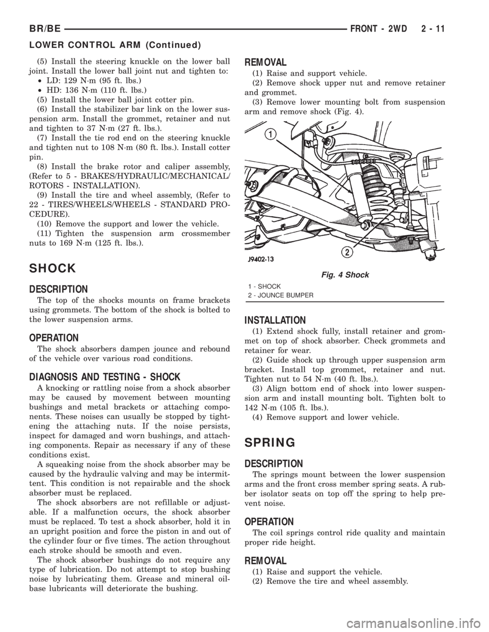
arm and remove shock (Fig. 4).
INSTALLATION
(1) Extend shock fully, install retainer and grom-
met on top of shock absorber. Check grommets and
retainer for wear.
(2) Guide shock up through upper suspension arm
bracket. Install top grommet, retainer and nut.
Tighten nut to 54 N´m (40 ft. lbs.).
(3) Align bottom end of shock into lower suspen-
sion arm and install mounting bolt. Tighten bolt to
142 N´m (105 ft. lbs.).
(4) Remove support and lower vehicle.
SPRING
DESCRIPTION
The springs mount between the lower suspension
arms and the front cross member spring seats. A rub-
ber isolator seats on top off the spring to help pre-
vent noise.
OPERATION
The coil springs control ride quality and maintain
proper ride height.
REMOVAL
(1) Raise and support the vehicle.
(2) Remove the tire and wheel assembly.
Fig. 4 Shock
1 - SHOCK
2 - JOUNCE BUMPER
BR/BEFRONT - 2WD 2 - 11
LOWER CONTROL ARM (Continued)
Page 64 of 2889

SHOCK
DESCRIPTION
The shocks are mounted inside the springs and
attached at the top to brackets with grommets. These
brackets are bolted on the frame with three studs on
a ring. The shock is mounted at the bottom of the
axle below the spring seat.
OPERATION
The shock absorbers dampen the jounce and
rebound of the vehicle over various road conditions.
DIAGNOSIS AND TESTING - SHOCK
A knocking or rattling noise from a shock absorber
may be caused by movement between mounting
bushings and metal brackets or attaching compo-
nents. These noises can usually be stopped by tight-
ening the attaching nuts. If the noise persists,
inspect for damaged and worn bushings, and attach-
ing components. Repair as necessary if any of these
conditions exist.
A squeaking noise from the shock absorber may be
caused by the hydraulic valving and may be intermit-
tent. This condition is not repairable and the shock
absorber must be replaced.
The shock absorbers are not refillable or adjust-
able. If a malfunction occurs, the shock absorbermust be replaced. To test a shock absorber, hold it in
an upright position and force the piston in and out of
the cylinder four or five times. The action throughout
each stroke should be smooth and even.
The shock absorber bushings do not require any
type of lubrication. Do not attempt to stop bushing
noise by lubricating them. Grease and mineral oil-
base lubricants will deteriorate the bushing.
REMOVAL
(1) Remove the nut, retainer and grommet from
the upper stud in the engine compartment.
(2) Remove three nuts from the upper shock
bracket (Fig. 16) .
(3) Remove the lower bolt from the axle bracket
(Fig. 17) . Remove the shock absorber from engine
compartment.
INSTALLATION
(1) Position the lower retainer and grommet on the
upper stud. Insert the shock absorber through the
spring from engine compartment.
(2) Install the lower bolt and tighten to 135 N´m
(100 ft. lbs.).
(3) Install the upper shock bracket and three nuts.
Tighten nuts to 75 N´m (55 ft. lbs.).
Fig. 15 Cam Adjuster
1 - ADJUSTMENT CAM
2 - AXLE BRACKET
3 - BRACKET REINFORCEMENT
4 - LOWER SUSPENSION ARM
Fig. 16 Shock Absorber and Bracket
1 - GROMMET
2 - RETAINER
3 - BRACKET
4 - RETAINER
5 - SHOCK
6 - GROMMET
BR/BEFRONT - 4WD 2 - 21
LOWER CONTROL ARM (Continued)
Page 69 of 2889
REAR
TABLE OF CONTENTS
page page
REAR
DESCRIPTION...........................26
DIAGNOSIS AND TESTING.................26
SPRING AND SHOCK....................26
SPECIFICATIONS........................27
SPECIAL TOOLS.........................28
BUSHINGS
REMOVAL..............................28
INSTALLATION...........................28
JOUNCE BUMPER
DESCRIPTION...........................28
OPERATION.............................28
SHOCK
DESCRIPTION...........................28OPERATION.............................28
REMOVAL..............................28
INSTALLATION...........................28
SPRING
DESCRIPTION...........................28
OPERATION.............................28
REMOVAL..............................28
INSTALLATION...........................29
STABILIZER BAR
DESCRIPTION...........................30
OPERATION.............................30
REMOVAL..............................30
INSTALLATION...........................30
REAR
DESCRIPTION
The rear suspension is comprised of:
²Shock Absorbers
²Jounce Bumpers
²Stabilizer Bar (optional)
²Leaf Springs
²Drive Axle
CAUTION: A vehicle should always be loaded so
the vehicle weight center-line is located immedi-
ately forward of the rear axle. Correct vehicle load-
ing provides proper front tire-to-road contact. This
results in maximum vehicle handling stability and
safety. Incorrect vehicle weight distribution can
cause excessive tire tread wear, spring fatigue or
failure, and erratic steering.
CAUTION: Suspension components with rubber/ure-
thane bushings (except stabilizer bar) should be
tightened with the vehicle at normal ride height. It is
important to have the springs supporting the weight
of the vehicle when the fasteners are torqued. If
springs are not at their normal ride position, vehicle
ride comfort could be affected and premature bush-
ing wear may occur.
DIAGNOSIS AND TESTING - SPRING AND
SHOCK
A knocking or rattling noise from a shock absorber
may be caused by movement between mounting
bushings and metal brackets or attaching compo-
nents. These noises can usually be stopped by tight-
ening the attaching nuts. If the noise persists,
inspect for damaged and worn bushings, and attach-
ing components. Repair as necessary if any of these
conditions exist.
A squeaking noise from the shock absorber may be
caused by the hydraulic valving and may be intermit-
tent. This condition is not repairable and the shock
absorber must be replaced.
The shock absorbers are not refillable or adjust-
able. If a malfunction occurs, the shock absorber
must be replaced. To test a shock absorber, hold it in
an upright position and force the piston in and out of
the cylinder four or five times. The action throughout
each stroke should be smooth and even.
The spring eye and shock absorber bushings do not
require any type of lubrication. Do not attempt to
stop spring bushing noise by lubricating them.
Grease and mineral oil-base lubricants will deterio-
rate the bushing rubber.
If the vehicle is used for severe, off-road operation,
the springs should be examined periodically. Check
for broken and shifted leafs, loose and missing clips,
and broken center bolts. Refer to Spring and Shock
Absorber Diagnosis chart for additional information.
2 - 26 REARBR/BE
Page 77 of 2889
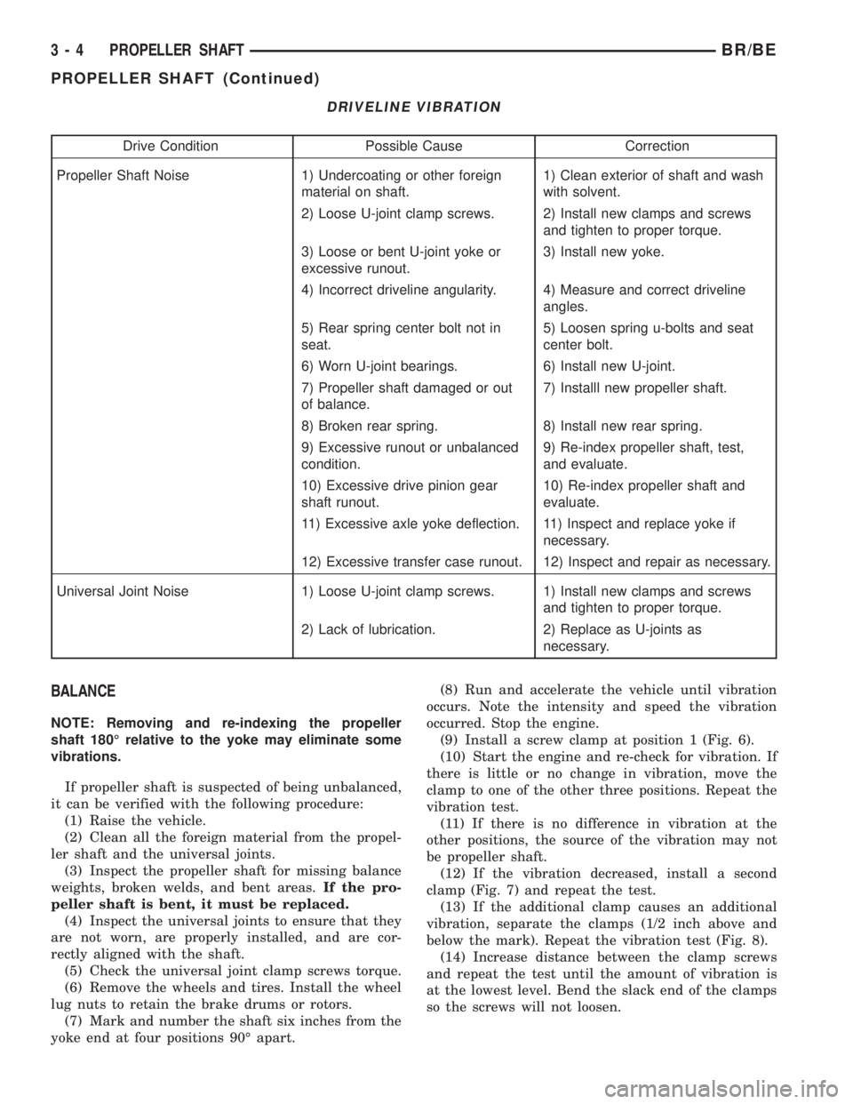
DRIVELINE VIBRATION
Drive Condition Possible Cause Correction
Propeller Shaft Noise 1) Undercoating or other foreign
material on shaft.1) Clean exterior of shaft and wash
with solvent.
2) Loose U-joint clamp screws. 2) Install new clamps and screws
and tighten to proper torque.
3) Loose or bent U-joint yoke or
excessive runout.3) Install new yoke.
4) Incorrect driveline angularity. 4) Measure and correct driveline
angles.
5) Rear spring center bolt not in
seat.5) Loosen spring u-bolts and seat
center bolt.
6) Worn U-joint bearings. 6) Install new U-joint.
7) Propeller shaft damaged or out
of balance.7) Installl new propeller shaft.
8) Broken rear spring. 8) Install new rear spring.
9) Excessive runout or unbalanced
condition.9) Re-index propeller shaft, test,
and evaluate.
10) Excessive drive pinion gear
shaft runout.10) Re-index propeller shaft and
evaluate.
11) Excessive axle yoke deflection. 11) Inspect and replace yoke if
necessary.
12) Excessive transfer case runout. 12) Inspect and repair as necessary.
Universal Joint Noise 1) Loose U-joint clamp screws. 1) Install new clamps and screws
and tighten to proper torque.
2) Lack of lubrication. 2) Replace as U-joints as
necessary.
BALANCE
NOTE: Removing and re-indexing the propeller
shaft 180É relative to the yoke may eliminate some
vibrations.
If propeller shaft is suspected of being unbalanced,
it can be verified with the following procedure:
(1) Raise the vehicle.
(2) Clean all the foreign material from the propel-
ler shaft and the universal joints.
(3) Inspect the propeller shaft for missing balance
weights, broken welds, and bent areas.If the pro-
peller shaft is bent, it must be replaced.
(4) Inspect the universal joints to ensure that they
are not worn, are properly installed, and are cor-
rectly aligned with the shaft.
(5) Check the universal joint clamp screws torque.
(6) Remove the wheels and tires. Install the wheel
lug nuts to retain the brake drums or rotors.
(7) Mark and number the shaft six inches from the
yoke end at four positions 90É apart.(8) Run and accelerate the vehicle until vibration
occurs. Note the intensity and speed the vibration
occurred. Stop the engine.
(9) Install a screw clamp at position 1 (Fig. 6).
(10) Start the engine and re-check for vibration. If
there is little or no change in vibration, move the
clamp to one of the other three positions. Repeat the
vibration test.
(11) If there is no difference in vibration at the
other positions, the source of the vibration may not
be propeller shaft.
(12) If the vibration decreased, install a second
clamp (Fig. 7) and repeat the test.
(13) If the additional clamp causes an additional
vibration, separate the clamps (1/2 inch above and
below the mark). Repeat the vibration test (Fig. 8).
(14) Increase distance between the clamp screws
and repeat the test until the amount of vibration is
at the lowest level. Bend the slack end of the clamps
so the screws will not loosen.
3 - 4 PROPELLER SHAFTBR/BE
PROPELLER SHAFT (Continued)
Page 88 of 2889
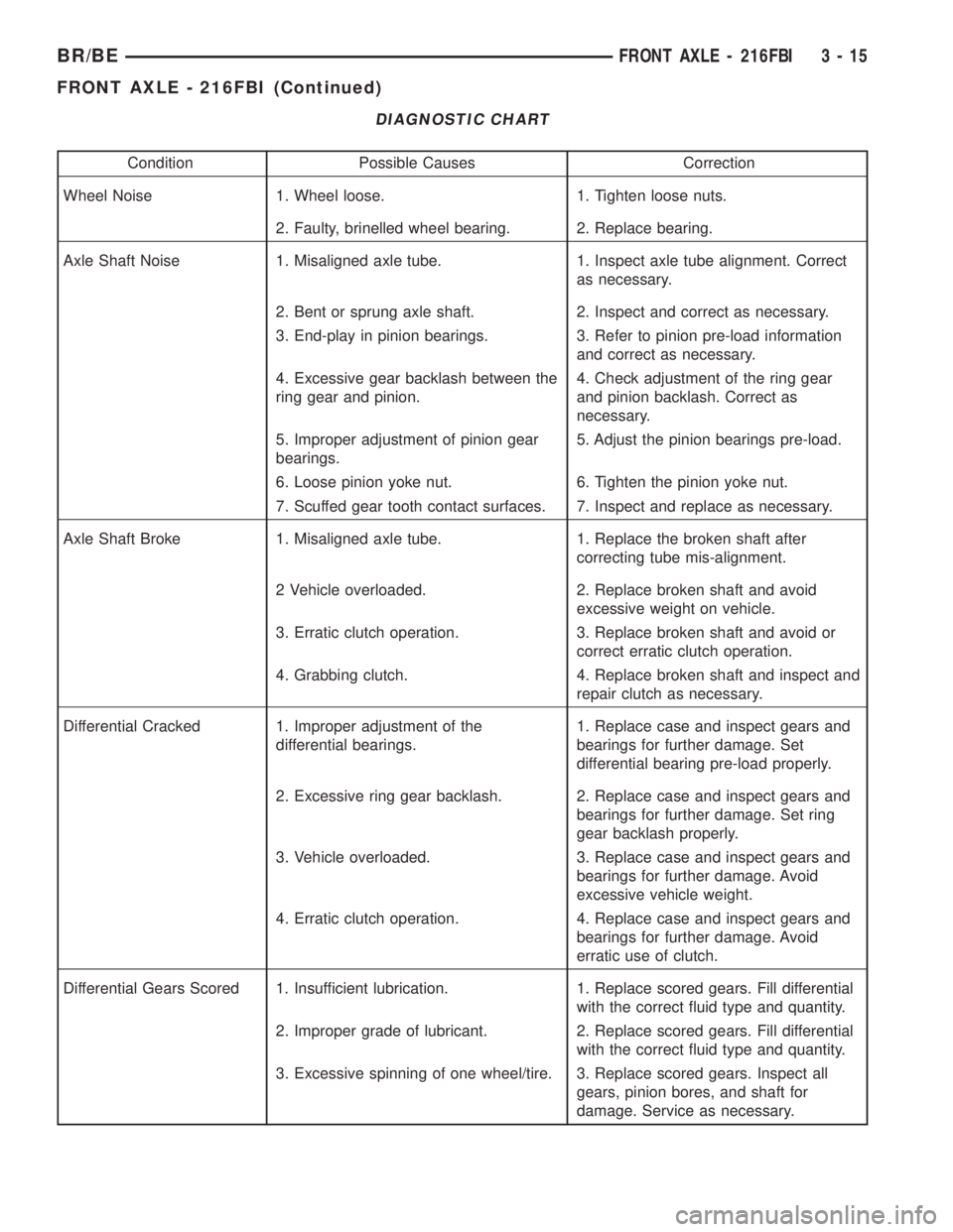
DIAGNOSTIC CHART
Condition Possible Causes Correction
Wheel Noise 1. Wheel loose. 1. Tighten loose nuts.
2. Faulty, brinelled wheel bearing. 2. Replace bearing.
Axle Shaft Noise 1. Misaligned axle tube. 1. Inspect axle tube alignment. Correct
as necessary.
2. Bent or sprung axle shaft. 2. Inspect and correct as necessary.
3. End-play in pinion bearings. 3. Refer to pinion pre-load information
and correct as necessary.
4. Excessive gear backlash between the
ring gear and pinion.4. Check adjustment of the ring gear
and pinion backlash. Correct as
necessary.
5. Improper adjustment of pinion gear
bearings.5. Adjust the pinion bearings pre-load.
6. Loose pinion yoke nut. 6. Tighten the pinion yoke nut.
7. Scuffed gear tooth contact surfaces. 7. Inspect and replace as necessary.
Axle Shaft Broke 1. Misaligned axle tube. 1. Replace the broken shaft after
correcting tube mis-alignment.
2 Vehicle overloaded. 2. Replace broken shaft and avoid
excessive weight on vehicle.
3. Erratic clutch operation. 3. Replace broken shaft and avoid or
correct erratic clutch operation.
4. Grabbing clutch. 4. Replace broken shaft and inspect and
repair clutch as necessary.
Differential Cracked 1. Improper adjustment of the
differential bearings.1. Replace case and inspect gears and
bearings for further damage. Set
differential bearing pre-load properly.
2. Excessive ring gear backlash. 2. Replace case and inspect gears and
bearings for further damage. Set ring
gear backlash properly.
3. Vehicle overloaded. 3. Replace case and inspect gears and
bearings for further damage. Avoid
excessive vehicle weight.
4. Erratic clutch operation. 4. Replace case and inspect gears and
bearings for further damage. Avoid
erratic use of clutch.
Differential Gears Scored 1. Insufficient lubrication. 1. Replace scored gears. Fill differential
with the correct fluid type and quantity.
2. Improper grade of lubricant. 2. Replace scored gears. Fill differential
with the correct fluid type and quantity.
3. Excessive spinning of one wheel/tire. 3. Replace scored gears. Inspect all
gears, pinion bores, and shaft for
damage. Service as necessary.
BR/BEFRONT AXLE - 216FBI 3 - 15
FRONT AXLE - 216FBI (Continued)
Page 89 of 2889
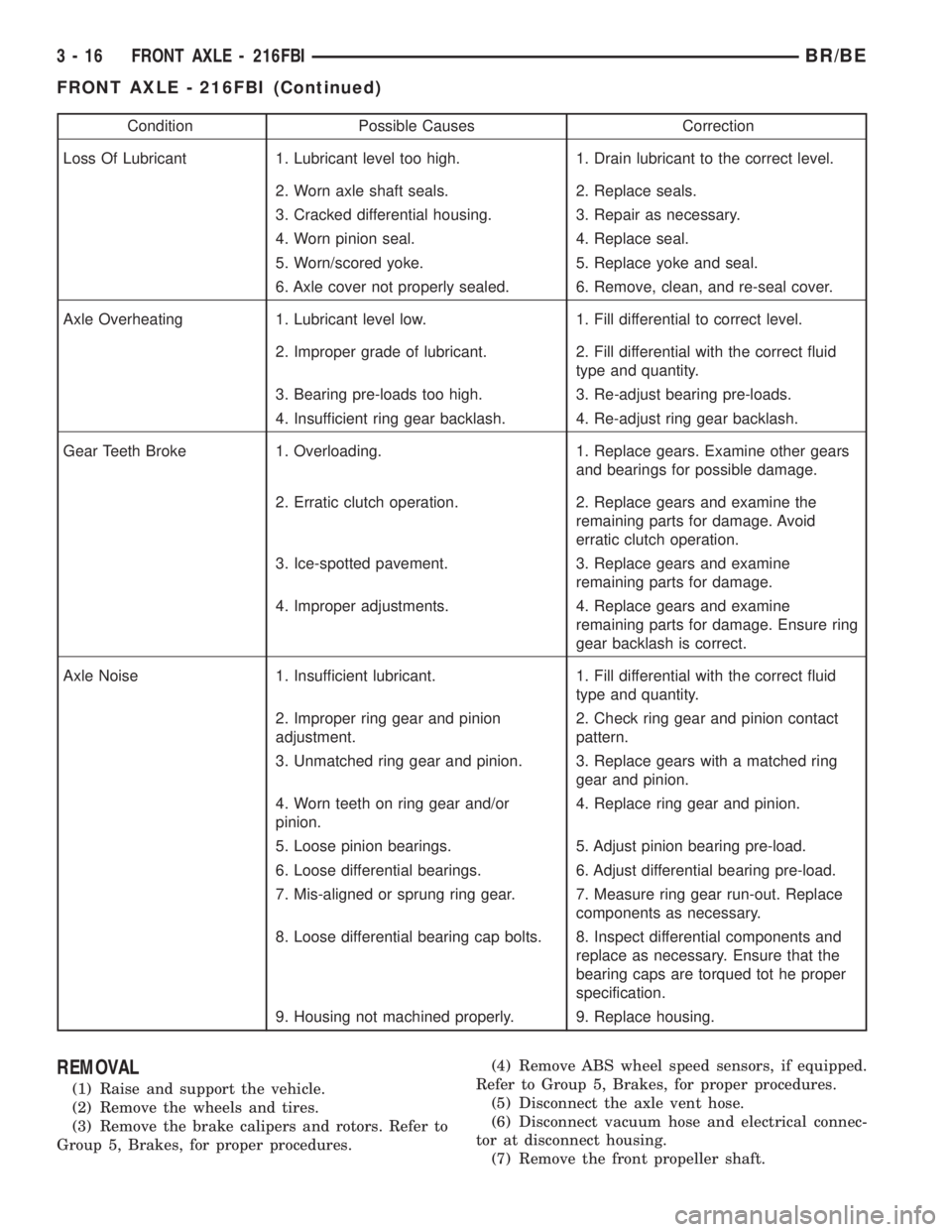
Condition Possible Causes Correction
Loss Of Lubricant 1. Lubricant level too high. 1. Drain lubricant to the correct level.
2. Worn axle shaft seals. 2. Replace seals.
3. Cracked differential housing. 3. Repair as necessary.
4. Worn pinion seal. 4. Replace seal.
5. Worn/scored yoke. 5. Replace yoke and seal.
6. Axle cover not properly sealed. 6. Remove, clean, and re-seal cover.
Axle Overheating 1. Lubricant level low. 1. Fill differential to correct level.
2. Improper grade of lubricant. 2. Fill differential with the correct fluid
type and quantity.
3. Bearing pre-loads too high. 3. Re-adjust bearing pre-loads.
4. Insufficient ring gear backlash. 4. Re-adjust ring gear backlash.
Gear Teeth Broke 1. Overloading. 1. Replace gears. Examine other gears
and bearings for possible damage.
2. Erratic clutch operation. 2. Replace gears and examine the
remaining parts for damage. Avoid
erratic clutch operation.
3. Ice-spotted pavement. 3. Replace gears and examine
remaining parts for damage.
4. Improper adjustments. 4. Replace gears and examine
remaining parts for damage. Ensure ring
gear backlash is correct.
Axle Noise 1. Insufficient lubricant. 1. Fill differential with the correct fluid
type and quantity.
2. Improper ring gear and pinion
adjustment.2. Check ring gear and pinion contact
pattern.
3. Unmatched ring gear and pinion. 3. Replace gears with a matched ring
gear and pinion.
4. Worn teeth on ring gear and/or
pinion.4. Replace ring gear and pinion.
5. Loose pinion bearings. 5. Adjust pinion bearing pre-load.
6. Loose differential bearings. 6. Adjust differential bearing pre-load.
7. Mis-aligned or sprung ring gear. 7. Measure ring gear run-out. Replace
components as necessary.
8. Loose differential bearing cap bolts. 8. Inspect differential components and
replace as necessary. Ensure that the
bearing caps are torqued tot he proper
specification.
9. Housing not machined properly. 9. Replace housing.
REMOVAL
(1) Raise and support the vehicle.
(2) Remove the wheels and tires.
(3) Remove the brake calipers and rotors. Refer to
Group 5, Brakes, for proper procedures.(4) Remove ABS wheel speed sensors, if equipped.
Refer to Group 5, Brakes, for proper procedures.
(5) Disconnect the axle vent hose.
(6) Disconnect vacuum hose and electrical connec-
tor at disconnect housing.
(7) Remove the front propeller shaft.
3 - 16 FRONT AXLE - 216FBIBR/BE
FRONT AXLE - 216FBI (Continued)