2001 CHRYSLER VOYAGER air condition
[x] Cancel search: air conditionPage 1870 of 4284
REMOVAL - BATTERY
WARNING: A SUITABLE PAIR OF HEAVY DUTY
RUBBER GLOVES SHOULD BE WORN WHEN
REMOVING OR SERVICING A BATTERY.
WARNING: SAFETY GLASSES SHOULD BE WORN
WHEN REMOVING OR SERVICING A BATTERY.
WARNING: REMOVE METALLIC JEWELRY TO
AVOID INJURY BY ACCIDENTAL ARCING OF BAT-
TERY CURRENT.
(1) Verify that the ignition switch and all accesso-
ries are OFF.
(2) Disconnect the battery cables from the battery
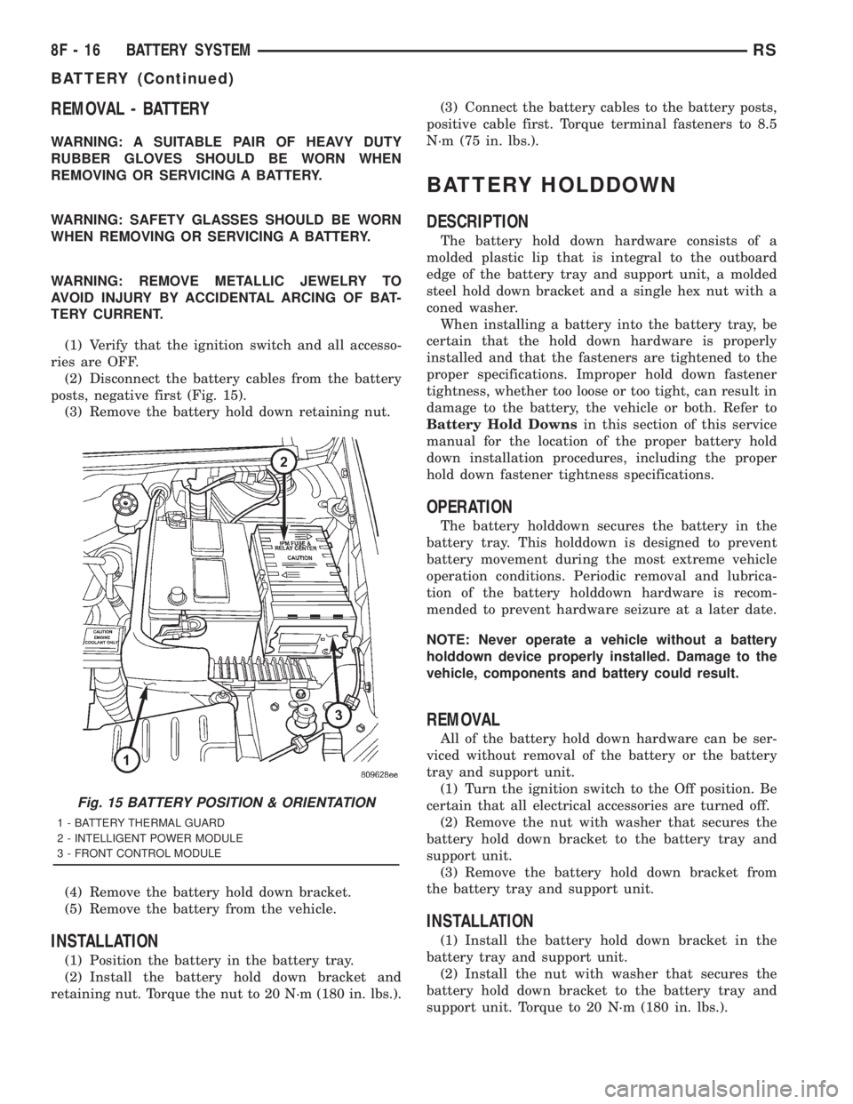
posts, negative first (Fig. 15).
(3) Remove the battery hold down retaining nut.
(4) Remove the battery hold down bracket.
(5) Remove the battery from the vehicle.
INSTALLATION
(1) Position the battery in the battery tray.
(2) Install the battery hold down bracket and
retaining nut. Torque the nut to 20 N´m (180 in. lbs.).(3) Connect the battery cables to the battery posts,
positive cable first. Torque terminal fasteners to 8.5
N´m (75 in. lbs.).
BATTERY HOLDDOWN
DESCRIPTION
The battery hold down hardware consists of a
molded plastic lip that is integral to the outboard
edge of the battery tray and support unit, a molded
steel hold down bracket and a single hex nut with a
coned washer.
When installing a battery into the battery tray, be
certain that the hold down hardware is properly
installed and that the fasteners are tightened to the
proper specifications. Improper hold down fastener
tightness, whether too loose or too tight, can result in
damage to the battery, the vehicle or both. Refer to
Battery Hold Downsin this section of this service
manual for the location of the proper battery hold
down installation procedures, including the proper
hold down fastener tightness specifications.
OPERATION
The battery holddown secures the battery in the
battery tray. This holddown is designed to prevent
battery movement during the most extreme vehicle
operation conditions. Periodic removal and lubrica-
tion of the battery holddown hardware is recom-
mended to prevent hardware seizure at a later date.
NOTE: Never operate a vehicle without a battery
holddown device properly installed. Damage to the
vehicle, components and battery could result.
REMOVAL
All of the battery hold down hardware can be ser-
viced without removal of the battery or the battery
tray and support unit.
(1) Turn the ignition switch to the Off position. Be
certain that all electrical accessories are turned off.
(2) Remove the nut with washer that secures the
battery hold down bracket to the battery tray and
support unit.
(3) Remove the battery hold down bracket from
the battery tray and support unit.
INSTALLATION
(1) Install the battery hold down bracket in the
battery tray and support unit.
(2) Install the nut with washer that secures the
battery hold down bracket to the battery tray and
support unit. Torque to 20 N´m (180 in. lbs.).
Fig. 15 BATTERY POSITION & ORIENTATION
1 - BATTERY THERMAL GUARD
2 - INTELLIGENT POWER MODULE
3 - FRONT CONTROL MODULE
8F - 16 BATTERY SYSTEMRS
BATTERY (Continued)
Page 1879 of 4284
GENERATOR DECOUPLER
PULLEY
DESCRIPTION
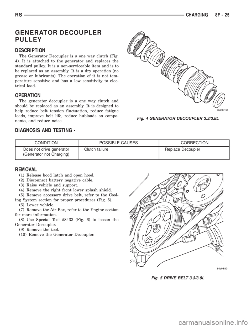
The Generator Decoupler is a one way clutch (Fig.
4). It is attached to the generator and replaces the
standard pulley. It is a non-serviceable item and is to
be replaced as an assembly. It is a dry operation (no
grease or lubricants). The operation of it is not tem-
perature sensitive and has a low sensitivity to elec-
trical load.
OPERATION
The generator decoupler is a one way clutch and
should be replaced as an assembly. It is designed to
help reduce belt tension fluctuation, reduce fatigue
loads, improve belt life, reduce hubloads on compo-
nents, and reduce noise.
DIAGNOSIS AND TESTING -
CONDITION POSSIBLE CAUSES CORRECTION
Does not drive generator
(Generator not Charging)Clutch failure Replace Decoupler
REMOVAL
(1) Release hood latch and open hood.
(2) Disconnect battery negative cable.
(3) Raise vehicle and support.
(4) Remove the right front lower splash shield.
(5) Remove accessory drive belt, refer to the Cool-
ing System section for proper procedures (Fig. 5).
(6) Lower vehicle.
(7) Remove the Air Box, refer to the Engine section
for more information.
(8) Use Special Tool #8433 (Fig. 6) to loosen the
Generator Decoupler.
(9) Remove the tool.
(10) Remove the Generator Decoupler.
Fig. 4 GENERATOR DECOUPLER 3.3/3.8L
Fig. 5 DRIVE BELT 3.3/3.8L
RSCHARGING8F-25
Page 1882 of 4284
²Battery- Visually inspect the battery for indi-
cations of physical damage and loose or corroded
cable connections. Determine the state-of-charge and
cranking capacity of the battery. Charge or replace
the battery, if required. Refer to the Battery section
for more information.
²Ignition Switch- Visually inspect the ignition
switch for indications of physical damage and loose
or corroded wire harness connections.
²Transmission Range Sensor- Visually inspect
the transmission range sensor for indications of phys-
ical damage and loose or corroded wire harness con-
nections.
²Starter Relay- Visually inspect the starter
relay for indications of physical damage and loose or
corroded wire harness connections.²Starter- Visually inspect the starter for indica-
tions of physical damage and loose or corroded wire
harness connections.
²Starter Solenoid- Visually inspect the starter
solenoid for indications of physical damage and loose
or corroded wire harness connections.
²Wiring- Visually inspect the wire harness for
damage. Repair or replace any faulty wiring, as
required. Check for loose or corroded wire harness
connections at main engine ground and remote jump
post.
²Power Distribution Center (PDC)- Visually
inspect the B+ connections at the PDC for physical
damage and loose or corroded harness connections.
STARTING SYSTEM DIAGNOSIS
CONDITION POSSIBLE CAUSE CORRECTION
STARTER FAILS
TO ENGAGE.1. BATTERY
DISCHARGED OR
FAULTY.1. REFER TO THE BATTERYSECTION FOR MORE
INFORMATION. CHARGE OR REPLACE BATTERY, IF
REQUIRED.
2. STARTING CIRCUIT
WIRING FAULTY.2. REFER TO FEED CIRCUIT RESISTANCE TEST AND FEED
CIRCUIT TEST IN THIS SECTION.
3. STARTER RELAY
FAULTY.3. REFER TO RELAY TEST, IN THIS SECTION. REPLACE
RELAY, IF NECESSARY.
4. IGNITION SWITCH
FAULTY.4. REFER TO IGNITION SWITCH TEST, IN THE STEERING
SECTION OR 8 WIRING DIAGRAMS. REPLACE SWITCH, IF
NECESSARY.
5. PARK/NEUTRAL
POSITION SWITCH
(AUTO TRANS) FAULTY
OR MIS-ADJUSTED.5. REFER PARK/NEUTRAL POSITION SWITCH TEST, IN THE
TRANSAXLE. SECTION FOR MORE INFORMATION. REPLACE
SWITCH, IF NECESSARY.
6. CLUTCH PEDAL
POSITION SWITCH
(MAN TRANS) FAULTY.6. REFER TO CLUTCH PEDAL POSITION SWITCH TEST, IN
THE CLUTCH. SECTION. REPLACE SWITCH, IF NECESSARY.
7. STARTER SOLENOID
FAULTY.7. REFER TO SOLENOID TEST, IN THIS SECTION. REPLACE
STARTER ASSEMBLY, IF NECESSARY.
8. STARTER ASSEMBLY
FAULTY.8. IF ALL OTHER STARTING SYSTEM COMPONENTS AND
CIRCUITS CHECK OK, REPLACE STARTER ASSEMBLY.
9. FAULTY TEETH ON
RING GEAR.9. ROTATE FLYWHEEL 360É, AND INSPECT TEETH AND RING
GEAR REPLACED IF DAMAGED.
STARTER
ENGAGES,
FAILS TO TURN
ENGINE.1. BATTERY
DISCHARGED OR
FAULTY.1. REFER TO THE BATTERY SECTION FOR MORE
INFORMATION. CHARGE OR REPLACE BATTERY AS
NECESSARY.
2. STARTING CIRCUIT
WIRING FAULTY.2. REFER TO THE FEED CIRCUIT RESISTANCE TEST AND
THE FEED CIRCUIT TEST IN THIS SECTION. REPAIR AS
NECESSARY.
8F - 28 STARTINGRS
STARTING (Continued)
Page 1899 of 4284
WINDSHIELD GRID
DIAGNOSIS AND TESTING - SYSTEM TEST
Electrically heated rear window defogger or the
heated windshield wiper deicer operation can be
checked on the vehicle in the following manner:
(1) Turn the ignition switch to the ON position.
(2) Using a ammeter on the battery, turn the rear
defogger control switch to the ON position, a distinct
increase in amperage draw should be noted.
(3) The rear window defogger or the heated wind-
shield wiper deicer operation can be checked by feel-
ing the glass. A distinct difference in temperature
between the grid lines and adjacent clear glass can
be detected in 3 to 4 minutes of operation.
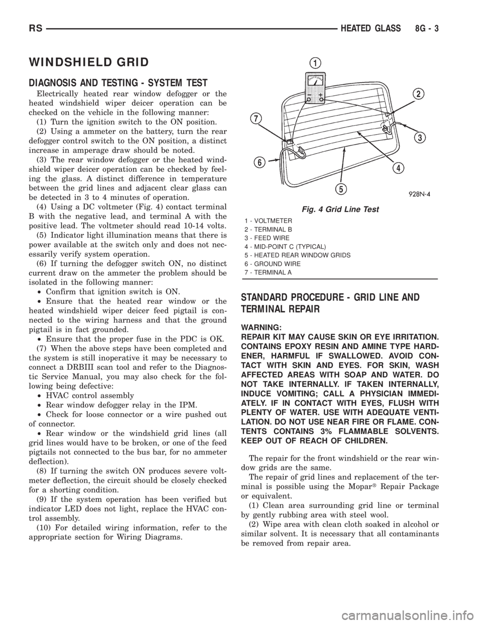
(4) Using a DC voltmeter (Fig. 4) contact terminal
B with the negative lead, and terminal A with the
positive lead. The voltmeter should read 10-14 volts.
(5) Indicator light illumination means that there is
power available at the switch only and does not nec-
essarily verify system operation.
(6) If turning the defogger switch ON, no distinct
current draw on the ammeter the problem should be
isolated in the following manner:
²Confirm that ignition switch is ON.
²Ensure that the heated rear window or the
heated windshield wiper deicer feed pigtail is con-
nected to the wiring harness and that the ground
pigtail is in fact grounded.
²Ensure that the proper fuse in the PDC is OK.
(7) When the above steps have been completed and
the system is still inoperative it may be necessary to
connect a DRBIII scan tool and refer to the Diagnos-
tic Service Manual, you may also check for the fol-
lowing being defective:
²HVAC control assembly
²Rear window defogger relay in the IPM.
²Check for loose connector or a wire pushed out
of connector.
²Rear window or the windshield grid lines (all
grid lines would have to be broken, or one of the feed
pigtails not connected to the bus bar, for no ammeter
deflection).
(8) If turning the switch ON produces severe volt-
meter deflection, the circuit should be closely checked
for a shorting condition.
(9) If the system operation has been verified but
indicator LED does not light, replace the HVAC con-
trol assembly.
(10) For detailed wiring information, refer to the
appropriate section for Wiring Diagrams.
STANDARD PROCEDURE - GRID LINE AND
TERMINAL REPAIR
WARNING:
REPAIR KIT MAY CAUSE SKIN OR EYE IRRITATION.
CONTAINS EPOXY RESIN AND AMINE TYPE HARD-
ENER, HARMFUL IF SWALLOWED. AVOID CON-
TACT WITH SKIN AND EYES. FOR SKIN, WASH
AFFECTED AREAS WITH SOAP AND WATER. DO
NOT TAKE INTERNALLY. IF TAKEN INTERNALLY,
INDUCE VOMITING; CALL A PHYSICIAN IMMEDI-
ATELY. IF IN CONTACT WITH EYES, FLUSH WITH
PLENTY OF WATER. USE WITH ADEQUATE VENTI-
LATION. DO NOT USE NEAR FIRE OR FLAME. CON-
TENTS CONTAINS 3% FLAMMABLE SOLVENTS.
KEEP OUT OF REACH OF CHILDREN.
The repair for the front windshield or the rear win-
dow grids are the same.
The repair of grid lines and replacement of the ter-
minal is possible using the MopartRepair Package
or equivalent.
(1) Clean area surrounding grid line or terminal
by gently rubbing area with steel wool.
(2) Wipe area with clean cloth soaked in alcohol or
similar solvent. It is necessary that all contaminants
be removed from repair area.
Fig. 4 Grid Line Test
1 - VOLTMETER
2 - TERMINAL B
3 - FEED WIRE
4 - MID-POINT C (TYPICAL)
5 - HEATED REAR WINDOW GRIDS
6 - GROUND WIRE
7 - TERMINAL A
RSHEATED GLASS8G-3
Page 1912 of 4284
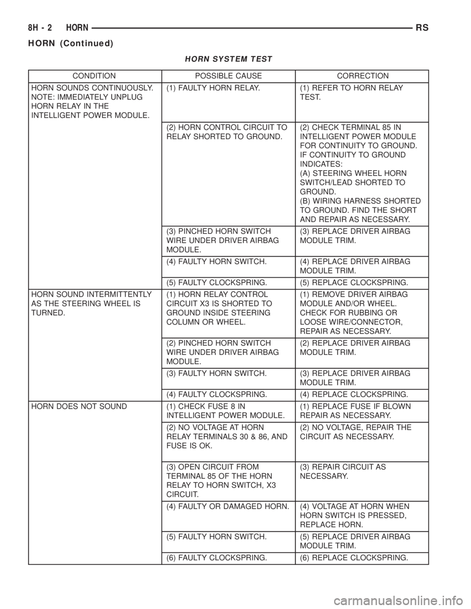
HORN SYSTEM TEST
CONDITION POSSIBLE CAUSE CORRECTION
HORN SOUNDS CONTINUOUSLY.
NOTE: IMMEDIATELY UNPLUG
HORN RELAY IN THE
INTELLIGENT POWER MODULE.(1) FAULTY HORN RELAY. (1) REFER TO HORN RELAY
TEST.
(2) HORN CONTROL CIRCUIT TO
RELAY SHORTED TO GROUND.(2) CHECK TERMINAL 85 IN
INTELLIGENT POWER MODULE
FOR CONTINUITY TO GROUND.
IF CONTINUITY TO GROUND
INDICATES:
(A) STEERING WHEEL HORN
SWITCH/LEAD SHORTED TO
GROUND.
(B) WIRING HARNESS SHORTED
TO GROUND. FIND THE SHORT
AND REPAIR AS NECESSARY.
(3) PINCHED HORN SWITCH
WIRE UNDER DRIVER AIRBAG
MODULE.(3) REPLACE DRIVER AIRBAG
MODULE TRIM.
(4) FAULTY HORN SWITCH. (4) REPLACE DRIVER AIRBAG
MODULE TRIM.
(5) FAULTY CLOCKSPRING. (5) REPLACE CLOCKSPRING.
HORN SOUND INTERMITTENTLY
AS THE STEERING WHEEL IS
TURNED.(1) HORN RELAY CONTROL
CIRCUIT X3 IS SHORTED TO
GROUND INSIDE STEERING
COLUMN OR WHEEL.(1) REMOVE DRIVER AIRBAG
MODULE AND/OR WHEEL.
CHECK FOR RUBBING OR
LOOSE WIRE/CONNECTOR,
REPAIR AS NECESSARY.
(2) PINCHED HORN SWITCH
WIRE UNDER DRIVER AIRBAG
MODULE.(2) REPLACE DRIVER AIRBAG
MODULE TRIM.
(3) FAULTY HORN SWITCH. (3) REPLACE DRIVER AIRBAG
MODULE TRIM.
(4) FAULTY CLOCKSPRING. (4) REPLACE CLOCKSPRING.
HORN DOES NOT SOUND (1) CHECK FUSE 8 IN
INTELLIGENT POWER MODULE.(1) REPLACE FUSE IF BLOWN
REPAIR AS NECESSARY.
(2) NO VOLTAGE AT HORN
RELAY TERMINALS 30 & 86, AND
FUSE IS OK.(2) NO VOLTAGE, REPAIR THE
CIRCUIT AS NECESSARY.
(3) OPEN CIRCUIT FROM
TERMINAL 85 OF THE HORN
RELAY TO HORN SWITCH, X3
CIRCUIT.(3) REPAIR CIRCUIT AS
NECESSARY.
(4) FAULTY OR DAMAGED HORN. (4) VOLTAGE AT HORN WHEN
HORN SWITCH IS PRESSED,
REPLACE HORN.
(5) FAULTY HORN SWITCH. (5) REPLACE DRIVER AIRBAG
MODULE TRIM.
(6) FAULTY CLOCKSPRING. (6) REPLACE CLOCKSPRING.
8H - 2 HORNRS
HORN (Continued)
Page 1913 of 4284
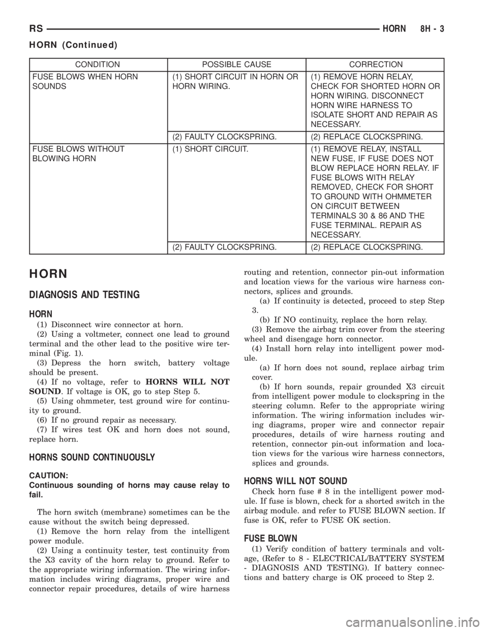
CONDITION POSSIBLE CAUSE CORRECTION
FUSE BLOWS WHEN HORN
SOUNDS(1) SHORT CIRCUIT IN HORN OR
HORN WIRING.(1) REMOVE HORN RELAY,
CHECK FOR SHORTED HORN OR
HORN WIRING. DISCONNECT
HORN WIRE HARNESS TO
ISOLATE SHORT AND REPAIR AS
NECESSARY.
(2) FAULTY CLOCKSPRING. (2) REPLACE CLOCKSPRING.
FUSE BLOWS WITHOUT
BLOWING HORN(1) SHORT CIRCUIT. (1) REMOVE RELAY, INSTALL
NEW FUSE, IF FUSE DOES NOT
BLOW REPLACE HORN RELAY. IF
FUSE BLOWS WITH RELAY
REMOVED, CHECK FOR SHORT
TO GROUND WITH OHMMETER
ON CIRCUIT BETWEEN
TERMINALS 30 & 86 AND THE
FUSE TERMINAL. REPAIR AS
NECESSARY.
(2) FAULTY CLOCKSPRING. (2) REPLACE CLOCKSPRING.
HORN
DIAGNOSIS AND TESTING
HORN
(1) Disconnect wire connector at horn.
(2) Using a voltmeter, connect one lead to ground
terminal and the other lead to the positive wire ter-
minal (Fig. 1).
(3) Depress the horn switch, battery voltage
should be present.
(4) If no voltage, refer toHORNS WILL NOT
SOUND. If voltage is OK, go to step Step 5.
(5) Using ohmmeter, test ground wire for continu-
ity to ground.
(6) If no ground repair as necessary.
(7) If wires test OK and horn does not sound,
replace horn.
HORNS SOUND CONTINUOUSLY
CAUTION:
Continuous sounding of horns may cause relay to
fail.
The horn switch (membrane) sometimes can be the
cause without the switch being depressed.
(1) Remove the horn relay from the intelligent
power module.
(2) Using a continuity tester, test continuity from
the X3 cavity of the horn relay to ground. Refer to
the appropriate wiring information. The wiring infor-
mation includes wiring diagrams, proper wire and
connector repair procedures, details of wire harnessrouting and retention, connector pin-out information
and location views for the various wire harness con-
nectors, splices and grounds.
(a) If continuity is detected, proceed to step Step
3.
(b) If NO continuity, replace the horn relay.
(3) Remove the airbag trim cover from the steering
wheel and disengage horn connector.
(4) Install horn relay into intelligent power mod-
ule.
(a) If horn does not sound, replace airbag trim
cover.
(b) If horn sounds, repair grounded X3 circuit
from intelligent power module to clockspring in the
steering column. Refer to the appropriate wiring
information. The wiring information includes wir-
ing diagrams, proper wire and connector repair
procedures, details of wire harness routing and
retention, connector pin-out information and loca-
tion views for the various wire harness connectors,
splices and grounds.HORNS WILL NOT SOUND
Check horn fuse#8intheintelligent power mod-
ule. If fuse is blown, check for a shorted switch in the
airbag module. and refer to FUSE BLOWN section. If
fuse is OK, refer to FUSE OK section.
FUSE BLOWN
(1) Verify condition of battery terminals and volt-
age, (Refer to 8 - ELECTRICAL/BATTERY SYSTEM
- DIAGNOSIS AND TESTING). If battery connec-
tions and battery charge is OK proceed to Step 2.
RSHORN8H-3
HORN (Continued)
Page 1925 of 4284
CAUTION: Cleaning of the platinum plug may dam-
age the platinum tip.
REMOVAL
When replacing the spark plugs and spark plug
cables, route the cables correctly and secure them in
the appropriate retainers. Failure to route the cables
properly can cause the radio to reproduce ignition
noise, cross ignition of the spark plugs orshort cir-
cuit the cables to ground.
Always remove cables by grasping at the boot,
rotating the boot 1/2 turn, and pulling straight back
in a steady motion.
(1) Prior to removing the spark plug, spray com-
pressed air around the spark plug hole and the area
around the spark plug.
(2) Remove the spark plug using a quality socket
with a foam insert.
(3) Inspect the spark plug condition.
INSTALLATION
When replacing the spark plugs and spark plug
cables, route the cables correctly and secure them in
the appropriate retainers. Failure to route the cables
properly can cause the radio to reproduce ignition
noise, cross ignition of the spark plugs orshort cir-
cuit the cables to ground.(1) To avoid cross threading, start the spark plug
into the cylinder head by hand.
(2) Tighten spark plugs to 17.5 N´m (13 ft. lbs.)
torque.
(3) Install spark plug cables over spark plugs. A
click will be heard and felt when the cable properly
attaches to the spark plug.
SPARK PLUG CABLE
DESCRIPTION
Spark Plug cables are sometimes referred to as
secondary ignition wires. The wires transfer electri-
cal current from the ignition coil pack to individual
spark plugs at each cylinder. The resistive spark plug
cables are of nonmetallic construction. The cables
provide suppression of radio frequency emissions
from the ignition system.
Check the spark plug cable connections for good
contact at the coil, and spark plugs. Terminals should
be fully seated. The insulators should be in good con-
dition and should fit tightly on the coil, and spark
plugs. Spark plug cables with insulators that are
cracked or torn must be replaced.
Clean Spark Plug cables with a cloth moistened
with a non-flammable solvent. Wipe the cables dry.
Check for brittle or cracked insulation. The spark
plug cables and spark plug boots are made from high
temperature silicone materials. All spark plug cable
leads are properly identified with cylinder numbers.
The inside of most the spark plug boot is coated with
a special high temperature silicone grease for greater
sealing and to minimize boot bonding to the spark
plug insulator.
REMOVAL
Failure to route the cables properly could cause the
radio to reproduce ignition noise, cross ignition of the
spark plugs or short circuit the cables to ground.
Remove spark plug cable from coil first.
Always remove the spark plug cable by grasping
the top of the spark plug insulator, turning the boot
1/2 turn and pulling straight up in a steady motion.
INSTALLATION
Failure to route the cables properly could cause the
radio to reproduce ignition noise, cross ignition of the
spark plugs or short circuit the cables to ground.
Install spark plug insulators over spark plugs.
Ensure the top of the spark plug insulator covers the
upper end of the spark plug tube.Then connect the
other end to coil pack.
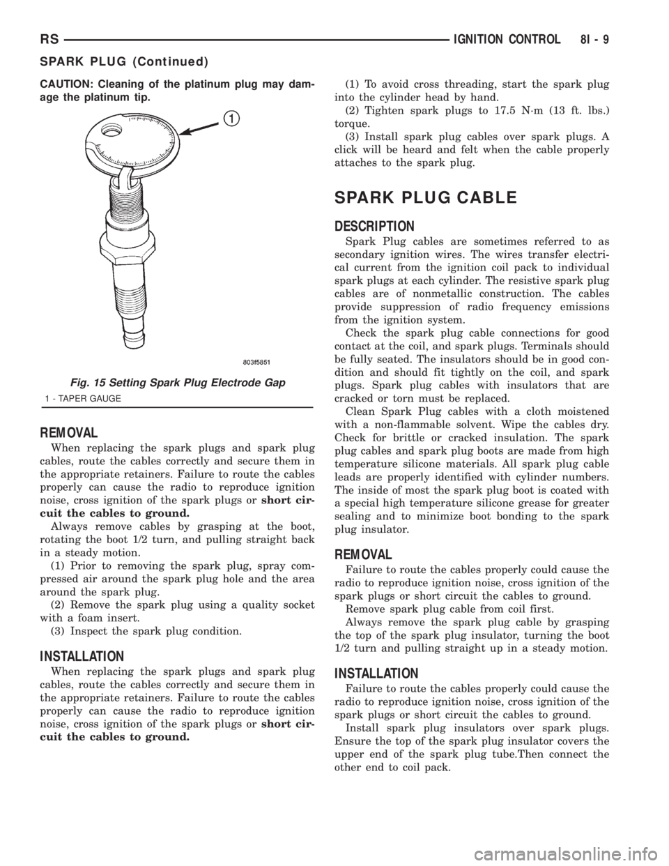
Fig. 15 Setting Spark Plug Electrode Gap
1 - TAPER GAUGE
RSIGNITION CONTROL8I-9
SPARK PLUG (Continued)
Page 1927 of 4284
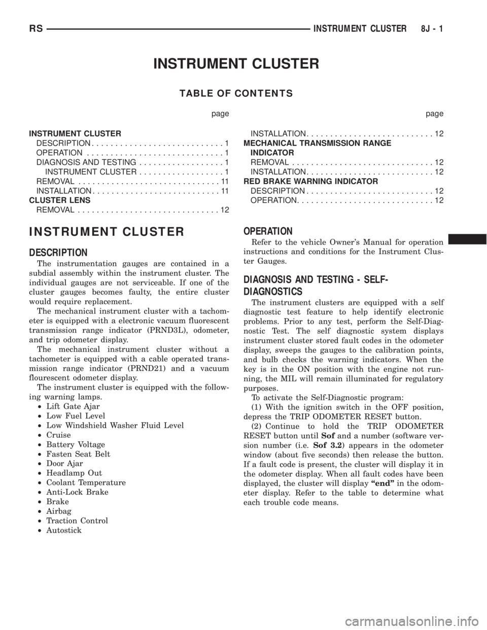
INSTRUMENT CLUSTER
TABLE OF CONTENTS
page page
INSTRUMENT CLUSTER
DESCRIPTION............................1
OPERATION.............................1
DIAGNOSIS AND TESTING..................1
INSTRUMENT CLUSTER..................1
REMOVAL..............................11
INSTALLATION...........................11
CLUSTER LENS
REMOVAL..............................12INSTALLATION...........................12
MECHANICAL TRANSMISSION RANGE
INDICATOR
REMOVAL..............................12
INSTALLATION...........................12
RED BRAKE WARNING INDICATOR
DESCRIPTION...........................12
OPERATION.............................12
INSTRUMENT CLUSTER
DESCRIPTION
The instrumentation gauges are contained in a
subdial assembly within the instrument cluster. The
individual gauges are not serviceable. If one of the
cluster gauges becomes faulty, the entire cluster
would require replacement.
The mechanical instrument cluster with a tachom-
eter is equipped with a electronic vacuum fluorescent
transmission range indicator (PRND3L), odometer,
and trip odometer display.
The mechanical instrument cluster without a
tachometer is equipped with a cable operated trans-
mission range indicator (PRND21) and a vacuum
flourescent odometer display.
The instrument cluster is equipped with the follow-
ing warning lamps.
²Lift Gate Ajar
²Low Fuel Level
²Low Windshield Washer Fluid Level
²Cruise
²Battery Voltage
²Fasten Seat Belt
²Door Ajar
²Headlamp Out
²Coolant Temperature
²Anti-Lock Brake
²Brake
²Airbag
²Traction Control
²Autostick
OPERATION
Refer to the vehicle Owner's Manual for operation
instructions and conditions for the Instrument Clus-
ter Gauges.
DIAGNOSIS AND TESTING - SELF-
DIAGNOSTICS
The instrument clusters are equipped with a self
diagnostic test feature to help identify electronic
problems. Prior to any test, perform the Self-Diag-
nostic Test. The self diagnostic system displays
instrument cluster stored fault codes in the odometer
display, sweeps the gauges to the calibration points,
and bulb checks the warning indicators. When the
key is in the ON position with the engine not run-
ning, the MIL will remain illuminated for regulatory
purposes.
To activate the Self-Diagnostic program:
(1) With the ignition switch in the OFF position,
depress the TRIP ODOMETER RESET button.
(2) Continue to hold the TRIP ODOMETER
RESET button untilSofand a number (software ver-
sion number (i.e.Sof 3.2) appears in the odometer
window (about five seconds) then release the button.
If a fault code is present, the cluster will display it in
the odometer display. When all fault codes have been
displayed, the cluster will displayªendºin the odom-
eter display. Refer to the table to determine what
each trouble code means.
RSINSTRUMENT CLUSTER8J-1