Page 3254 of 4284
OPERATION
NOTE: Refer to the Hydraulic Schematics for a
visual aid in determining valve location, operation
and design.
REGULATOR VALVE
The regulator valve controls hydraulic pressure in
the transaxle. It receives unregulated pressure from
the pump, which works against spring tension to
maintain oil at specific pressures. A system of sleeves
and ports allows the regulator valve to work at one of
three predetermined pressure levels. Regulated oil
pressure is also referred to as ªline pressure.º
SOLENOID SWITCH VALVE
The solenoid switch valve controls line pressure
from the LR/CC solenoid. In one position, it allows
the low/reverse clutch to be pressurized. In the other,
it directs line pressure to the converter control and
converter clutch valves.
MANUAL VALVE
The manual valve is operated by the mechanical
shift linkage. Its primary responsibility is to send
line pressure to the appropriate hydraulic circuits
and solenoids. The valve has three operating ranges
or positions.
CONVERTER CLUTCH SWITCH VALVE
The main responsibility of the converter clutch
switch valve is to control hydraulic pressure applied
to the front (off) side of the converter clutch piston.
Line pressure from the regulator valve is fed to the
torque converter regulator valve, where it passes
through the valve, and is slightly regulated. The
pressure is then directed to the converter clutch
switch valve and to the front side of the converter
clutch piston. This pressure pushes the piston back
and disengages the converter clutch.
CONVERTER CLUTCH CONTROL VALVE
The converter clutch control valve controls the
back (on) side of the torque converter clutch. When
the TCM energizes or modulates the LR/CC solenoid
to apply the converter clutch piston, both the con-
verter clutch control valve and the converter control
valve move, allowing pressure to be applied to the
back side of the clutch.
T/C REGULATOR VALVE
The torque converter regulator valve slightly regu-
lates the flow of fluid to the torque converter.
LOW/REVERSE SWITCH VALVE
The low/reverse clutch is applied from different
sources, depending on whether low (1st) gear or
reverse is selected. The low/reverse switch valve
alternates positions depending on from which direc-
tion fluid pressure is applied. By design, when the
valve is shifted by fluid pressure from one channel,
the opposing channel is blocked. The switch valve
alienates the possibility of a sticking ball check, thus
providing consistent application of the low/reverse
clutch under all operating conditions.
REMOVAL
NOTE: If valve body is replaced or reconditioned,
the TCM Quick Learn Procedure must be per-
formed. (Refer to 8 - ELECTRICAL/ELECTRONIC
CONTROL MODULES/TRANSMISSION CONTROL
MODULE - STANDARD PROCEDURE)
(1) Disconnect battery negative cable.
(2) Disconnect gearshift cable from manual valve
lever.
(3) Remove manual valve lever from manual shaft.
(4) Raise vehicle on hoist.
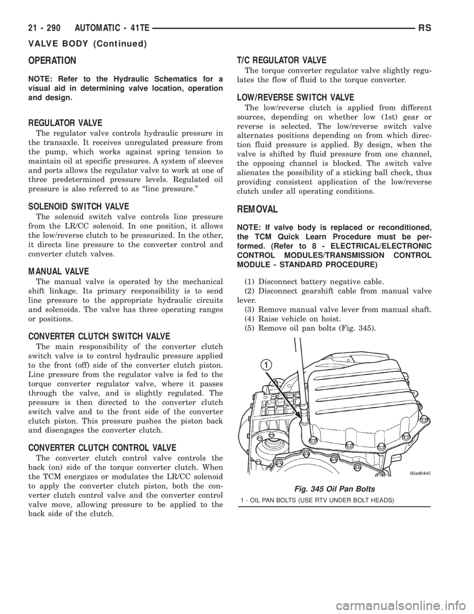
(5) Remove oil pan bolts (Fig. 345).
Fig. 345 Oil Pan Bolts
1 - OIL PAN BOLTS (USE RTV UNDER BOLT HEADS)
21 - 290 AUTOMATIC - 41TERS
VALVE BODY (Continued)
Page 3264 of 4284
(10) Install transfer plate to valve body and sepa-
rator plate. Make sure oil screen and #5 check valve
do not bind (Fig. 375).
(11) Install twenty-four transfer plate to valve
body screws (Fig. 376) and torque to 5 N´m (45 in.
lbs.).(12) Install 2/4 Accumulator components as shown
in (Fig. 377).
(13) Torque 2/4 Accumulator retainer to 5 N´m (45
in. lbs.) (Fig. 378).
Fig. 375 Install Transfer Plate
1 - TRANSFER PLATE
Fig. 376 Install Valve Body to Transfer Plate Screws
1 - SCREW (24)
2 - TRANSFER PLATE
3 - VALVE BODY
Fig. 377 2/4 Accumulator Assembly
1 - VALVE BODY
2 - RETAINER PLATE
3 - DETENT SPRING
4 - SPRINGS
5 - SEALS
6 - PISTON
Fig. 378 2/4 Accumulator Retaining Plate
1 - 2±4 ACCUMULATOR RETAINING PLATE
2 - DETENT SPRING
21 - 300 AUTOMATIC - 41TERS
VALVE BODY (Continued)
Page 3265 of 4284
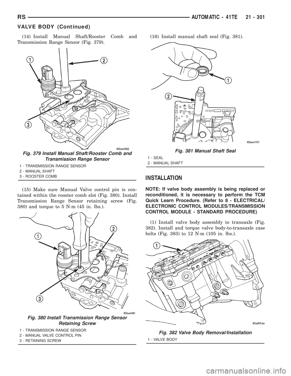
(14) Install Manual Shaft/Rooster Comb and
Transmission Range Sensor (Fig. 379).
(15) Make sure Manual Valve control pin is con-
tained within the rooster comb slot (Fig. 380). Install
Transmission Range Sensor retaining screw (Fig.
380) and torque to 5 N´m (45 in. lbs.).(16) Install manual shaft seal (Fig. 381).
INSTALLATION
NOTE: If valve body assembly is being replaced or
reconditioned, it is necessary to perform the TCM
Quick Learn Procedure. (Refer to 8 - ELECTRICAL/
ELECTRONIC CONTROL MODULES/TRANSMISSION
CONTROL MODULE - STANDARD PROCEDURE)
(1) Install valve body assembly to transaxle (Fig.
382). Install and torque valve body-to-transaxle case
bolts (Fig. 383) to 12 N´m (105 in. lbs.).
Fig. 379 Install Manual Shaft/Rooster Comb and
Transmission Range Sensor
1 - TRANSMISSION RANGE SENSOR
2 - MANUAL SHAFT
3 - ROOSTER COMB
Fig. 380 Install Transmission Range Sensor
Retaining Screw
1 - TRANSMISSION RANGE SENSOR
2 - MANUAL VALVE CONTROL PIN
3 - RETAINING SCREW
Fig. 381 Manual Shaft Seal
1 - SEAL
2 - MANUAL SHAFT
Fig. 382 Valve Body Removal/Installation
1 - VALVE BODY
RSAUTOMATIC - 41TE21 - 301
VALVE BODY (Continued)
Page 3266 of 4284
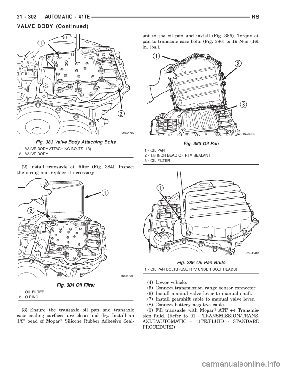
(2) Install transaxle oil filter (Fig. 384). Inspect
the o-ring and replace if necessary.
(3) Ensure the transaxle oil pan and transaxle
case sealing surfaces are clean and dry. Install an
1/8º bead of MopartSilicone Rubber Adhesive Seal-ant to the oil pan and install (Fig. 385). Torque oil
pan-to-transaxle case bolts (Fig. 386) to 19 N´m (165
in. lbs.).
(4) Lower vehicle.
(5) Connect transmission range sensor connector.
(6) Install manual valve lever to manual shaft.
(7) Install gearshift cable to manual valve lever.
(8) Connect battery negative cable.
(9) Fill transaxle with MopartATF +4 Transmis-
sion fluid. (Refer to 21 - TRANSMISSION/TRANS-
AXLE/AUTOMATIC - 41TE/FLUID - STANDARD
PROCEDURE)
Fig. 383 Valve Body Attaching Bolts
1 - VALVE BODY ATTACHING BOLTS (18)
2 - VALVE BODY
Fig. 384 Oil Filter
1 - OIL FILTER
2 - O-RING
Fig. 385 Oil Pan
1 - OIL PAN
2 - 1/8 INCH BEAD OF RTV SEALANT
3 - OIL FILTER
Fig. 386 Oil Pan Bolts
1 - OIL PAN BOLTS (USE RTV UNDER BOLT HEADS)
21 - 302 AUTOMATIC - 41TERS
VALVE BODY (Continued)
Page 3286 of 4284
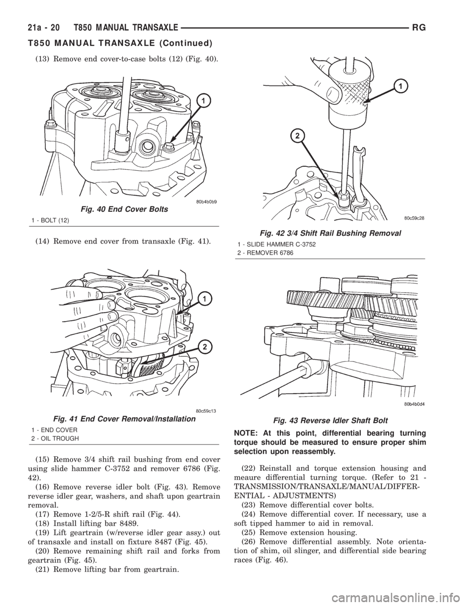
(13) Remove end cover-to-case bolts (12) (Fig. 40).
(14) Remove end cover from transaxle (Fig. 41).
(15) Remove 3/4 shift rail bushing from end cover
using slide hammer C-3752 and remover 6786 (Fig.
42).
(16) Remove reverse idler bolt (Fig. 43). Remove
reverse idler gear, washers, and shaft upon geartrain
removal.
(17) Remove 1-2/5-R shift rail (Fig. 44).
(18) Install lifting bar 8489.
(19) Lift geartrain (w/reverse idler gear assy.) out
of transaxle and install on fixture 8487 (Fig. 45).
(20) Remove remaining shift rail and forks from
geartrain (Fig. 45).
(21) Remove lifting bar from geartrain.NOTE: At this point, differential bearing turning
torque should be measured to ensure proper shim
selection upon reassembly.
(22) Reinstall and torque extension housing and
meaure differential turning torque. (Refer to 21 -
TRANSMISSION/TRANSAXLE/MANUAL/DIFFER-
ENTIAL - ADJUSTMENTS)
(23) Remove differential cover bolts.
(24) Remove differential cover. If necessary, use a
soft tipped hammer to aid in removal.
(25) Remove extension housing.
(26) Remove differential assembly. Note orienta-
tion of shim, oil slinger, and differential side bearing
races (Fig. 46).
Fig. 40 End Cover Bolts
1 - BOLT (12)
Fig. 41 End Cover Removal/Installation
1 - END COVER
2 - OIL TROUGH
Fig. 42 3/4 Shift Rail Bushing Removal
1 - SLIDE HAMMER C-3752
2 - REMOVER 6786
Fig. 43 Reverse Idler Shaft Bolt
21a - 20 T850 MANUAL TRANSAXLERG
T850 MANUAL TRANSAXLE (Continued)
Page 3288 of 4284
ASSEMBLY
NOTE: When assembling this transaxle, always use
NEW snap rings.
NOTE: Before assembling transaxle, differential
turning torque must be measured and adjusted.
(Refer to 21 - TRANSMISSION/TRANSAXLE/MANU-
AL/DIFFERENTIAL - ADJUSTMENTS). Differential
turning torque must be measured with geartrain out
of case.
(1) Install input shaft bearing using an arbor press
and remover/installer 8474 (Fig. 51).
(2) Install shift shaft bushing to case using
installer 8475 (Fig. 52).
Fig. 48 Intermediate Shaft Bearing Race Removal
1 - REMOVER 8472
Fig. 49 Shift Rail Bushing Removal
1 - SLIDE HAMMER C-3752
2 - REMOVER 6786
Fig. 50 Input Shaft Bearing Removal
1 - ARBOR PRESS
2 - DRIVER HANDLE C-4171
3 - REMOVER/INSTALLER 8474
21a - 22 T850 MANUAL TRANSAXLERG
T850 MANUAL TRANSAXLE (Continued)
Page 3290 of 4284
(7) Remove lifting bar 8489 from geartrain.
(8) Install shift 1/2-5/R rail as shown in (Fig. 56).
(9) Install reverse idler shaft into position (Fig.
57). Install and torque shaft-to-case bolt to 54 N´m
(40 ft. lbs.).(10) Install reverse idler gear bearing (Fig. 58).
(11) Install reverse idler gear with hub down as
shown in (Fig. 59).
(12) Install flat washer (Fig. 60).
(13) Install wave washer (Fig. 61).
(14) Install input shaft sealed roller bearing using
installer 8482 (Fig. 62).
(15) Installnewinput shaft bearing snap ring
(Fig. 63).
Fig. 54 Install Geartrain to Fixture 8487
1 - INTERMEDIATE SHAFT
2 - INPUT SHAFT
3 - FIXTURE 8487
Fig. 55 Shift Fork/Rail Orientation
1 - 5/R FORK
2 - 3/4 RAIL ASSEMBLY
3 - 3/4 FORK
4 - 1/2 FORK
21a - 24 T850 MANUAL TRANSAXLERG
T850 MANUAL TRANSAXLE (Continued)
Page 3293 of 4284
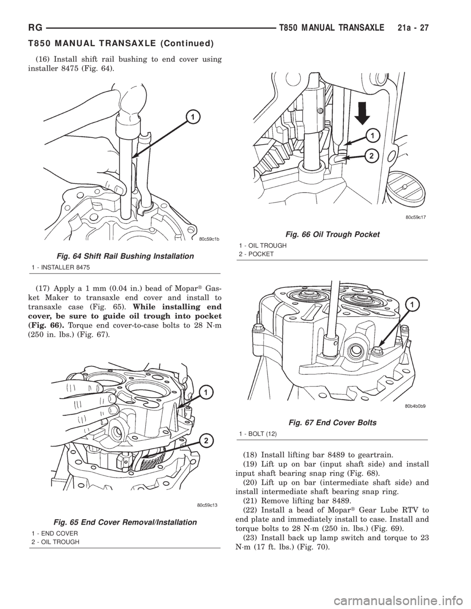
(16) Install shift rail bushing to end cover using
installer 8475 (Fig. 64).
(17) Applya1mm(0.04 in.) bead of MopartGas-
ket Maker to transaxle end cover and install to
transaxle case (Fig. 65).While installing end
cover, be sure to guide oil trough into pocket
(Fig. 66).Torque end cover-to-case bolts to 28 N´m
(250 in. lbs.) (Fig. 67).
(18) Install lifting bar 8489 to geartrain.
(19) Lift up on bar (input shaft side) and install
input shaft bearing snap ring (Fig. 68).
(20) Lift up on bar (intermediate shaft side) and
install intermediate shaft bearing snap ring.
(21) Remove lifting bar 8489.
(22) Install a bead of MopartGear Lube RTV to
end plate and immediately install to case. Install and
torque bolts to 28 N´m (250 in. lbs.) (Fig. 69).
(23) Install back up lamp switch and torque to 23
N´m (17 ft. lbs.) (Fig. 70).
Fig. 64 Shift Rail Bushing Installation
1 - INSTALLER 8475
Fig. 65 End Cover Removal/Installation
1 - END COVER
2 - OIL TROUGH
Fig. 66 Oil Trough Pocket
1 - OIL TROUGH
2 - POCKET
Fig. 67 End Cover Bolts
1 - BOLT (12)
RGT850 MANUAL TRANSAXLE21a-27
T850 MANUAL TRANSAXLE (Continued)