2001 CHRYSLER VOYAGER battery capacity
[x] Cancel search: battery capacityPage 3735 of 4284
(10) Install and tighten the nut that secures the
suction line fitting to the compressor. Tighten the nut
to 23 N´m (17 ft. lbs.).
(11) Reconnect the drain tube to the wiper module
drain on the right side of the engine compartment.
(12) Reinstall the air cleaner top cover and snorkel
onto the air cleaner housing located on the right side
of the engine compartment.
(13) Reconnect the battery negative cable.
(14) If the vehicle is equipped with the optional
rear air conditioner, go to Step 15. If the vehicle does
not have the optional rear air conditioner, go to Step
21.
(15) Raise and support the vehicle.
(16) Remove the tape or plugs from the suction
line extension fitting and the underbody suction line
fitting (Fig. 35).
(17) Lubricate a new rubber O-ring seal with clean
refrigerant oil and install it on the underbody suction
line fitting.
(18) Reconnect the suction line extension fitting to
the underbody suction line fitting. Tighten the fit-
tings to 23 N´m (17 ft. lbs.).
(19) Install a new tie strap just forward of the con-
nections between the underbody plumbing and the
engine compartment plumbing for the rear heater
and air conditioner.
(20) Lower the vehicle.
(21) Evacuate the refrigerant system. (Refer to 24
- HEATING & AIR CONDITIONING/PLUMBING -
FRONT/REFRIGERANT - STANDARD PROCE-
DURE - REFRIGERANT SYSTEM EVACUATE).
(22) Charge the refrigerant system. (Refer to 24 -
HEATING & AIR CONDITIONING/PLUMBING -
FRONT/REFRIGERANT - STANDARD PROCE-
DURE - REFRIGERANT SYSTEM CHARGE).UNDERBODY LINES
DESCRIPTION
The rear heater-A/C unit plumbing is used only on
models with the optional rear heater-A/C unit. The
formed metal rear heater-A/C unit suction line, liquid
line, and heater lines are available for separate ser-
vice replacement. The molded and straight heater
hoses used on the rear heater-A/C unit can be ser-
viced in the vehicle. Refer to Group 7 - Cooling Sys-
tem for the heater hose service procedures.
OPERATION
The rear heater and A/C lines are all serviced as
individual pieces. When disconnecting any line or
block ensure that the area around it is clean of any
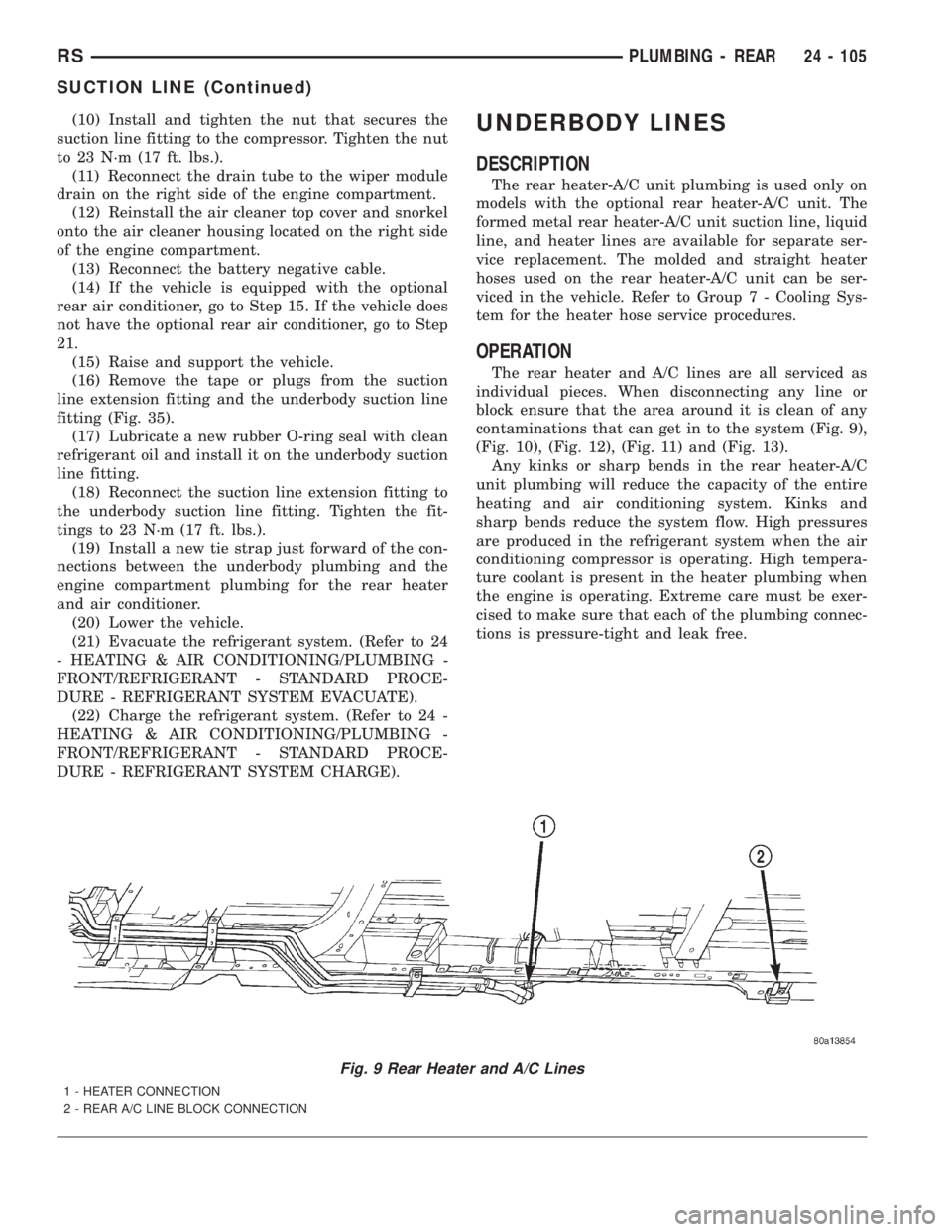
contaminations that can get in to the system (Fig. 9),
(Fig. 10), (Fig. 12), (Fig. 11) and (Fig. 13).
Any kinks or sharp bends in the rear heater-A/C
unit plumbing will reduce the capacity of the entire
heating and air conditioning system. Kinks and
sharp bends reduce the system flow. High pressures
are produced in the refrigerant system when the air
conditioning compressor is operating. High tempera-
ture coolant is present in the heater plumbing when
the engine is operating. Extreme care must be exer-
cised to make sure that each of the plumbing connec-
tions is pressure-tight and leak free.
Fig. 9 Rear Heater and A/C Lines
1 - HEATER CONNECTION
2 - REAR A/C LINE BLOCK CONNECTION
RSPLUMBING - REAR24 - 105
SUCTION LINE (Continued)
Page 3753 of 4284
²Vehicle Speed Sensor
²Engine Coolant Temperature Sensor
²Throttle Position Sensor
²Engine Controller Self Test Faults
²Cam or Crank Sensor
²Injector and Coil
²Idle Air Control Motor
²EVAP Electrical
²EGR Solenoid Electrical
²Intake Air Temperature
²5 Volt Feed
ConflictÐThe Task Manager does not run the
Oxygen Sensor Monitor if any of the following condi-
tions are present:
²A/C ON (A/C clutch cycling temporarily sus-
pends monitor)
²Purge flow in progress
²Ethanel content learn is takeng place and the
ethenal used once flag is set
SuspendÐThe Task Manager suspends maturing
a fault for the Oxygen Sensor Monitor if an of the fol-
lowing are present:
²Oxygen Sensor Heater Monitor, Priority 1
²Misfire Monitor, Priority 2
OXYGEN SENSOR HEATER MONITOR
DESCRIPTIONÐIf there is an oxygen sensor
(O2S) DTC as well as a O2S heater DTC, the O2S
fault MUST be repaired first. After the O2S fault is
repaired, verify that the heater circuit is operating
correctly.
The voltage readings taken from the O2S are very
temperature sensitive. The readings are not accurate
below 300ÉC. Heating of the O2S is done to allow the
engine controller to shift to closed loop control as
soon as possible. The heating element used to heat
the O2S must be tested to ensure that it is heating
the sensor properly.
The heater element itself is not tested. The sensor
output is used to test the heater by isolating the
effect of the heater element on the O2S output volt-
age from the other effects. The resistance is normally
between 100 ohms and 4.5 megaohms. When oxygen
sensor temperature increases, the resistance in the
internal circuit decreases. The PCM sends a 5 volts
biased signal through the oxygen sensors to ground
this monitoring circuit. As the temperature increases,
resistance decreases and the PCM detects a lower
voltage at the reference signal. Inversely, as the tem-
perature decreases, the resistance increases and the
PCM detects a higher voltage at the reference signal.
The O2S circuit is monitored for a drop in voltage.
OPERATIONÐThe Oxygen Sensor Heater Moni-
tor begins after the ignition has been turned OFF
and the O2 sensors have cooled. The PCM sends a 5
volt bias to the oxygen sensor every 1.6 seconds. ThePCM keeps it biased for 35 ms each time. As the sen-
sor cools down, the resistance increases and the PCM
reads the increase in voltage. Once voltage has
increased to a predetermined amount, higher than
when the test started, the oxygen sensor is cool
enough to test heater operation.
When the oxygen sensor is cool enough, the PCM
energizes the ASD relay. Voltage to the O2 sensor
begins to increase the temperature. As the sensor
temperature increases, the internal resistance
decreases. The PCM continues biasing the 5 volt sig-
nal to the sensor. Each time the signal is biased, the
PCM reads a voltage decrease. When the PCM
detects a voltage decrease of a predetermined value
for several biased pulses, the test passes.
The heater elements are tested each time the
engine is turned OFF if all the enabling conditions
are met. If the monitor fails, the PCM stores a
maturing fault and a Freeze Frame is entered. If two
consecutive tests fail, a DTC is stored. Because the
ignition is OFF, the MIL is illuminated at the begin-
ning of the next key cycle.
Enabling ConditionsÐThe following conditions
must be met for the PCM to run the oxygen sensor
heater test:
²Engine run time of at least 5.1 minutes
²Key OFF power down
²Battery voltage of at least 10 volts
²Sufficient Oxygen Sensor cool down
Pending ConditionsÐThere are not conditions or
situations that prompt conflict or suspension of test-
ing. The oxygen sensor heater test is not run pending
resolution of MIL illumination due to oxygen sensor
failure.
SuspendÐThere are no conditions which exist for
suspending the Heater Monitor.
CATALYST MONITOR
To comply with clean air regulations, vehicles are
equipped with catalytic converters. These converters
reduce the emission of hydrocarbons, oxides of nitro-
gen and carbon monoxide.
Normal vehicle miles or engine misfire can cause a
catalyst to decay. A meltdown of the ceramic core can
cause a reduction of the exhaust passage. This can
increase vehicle emissions and deteriorate engine
performance, driveability and fuel economy.
The catalyst monitor uses dual oxygen sensors
(O2S's) to monitor the efficiency of the converter. The
dual O2S strategy is based on the fact that as a cat-
alyst deteriorates, its oxygen storage capacity and its
efficiency are both reduced. By monitoring the oxy-
gen storage capacity of a catalyst, its efficiency can
be indirectly calculated. The upstream O2S is used to
detect the amount of oxygen in the exhaust gas
before the gas enters the catalytic converter. The
RSEMISSIONS CONTROL25-3
EMISSIONS CONTROL (Continued)
Page 3805 of 4284
important to block the wheels on front-wheel drive
vehicles; the parking brake does not hold the drive
wheels.
When servicing a vehicle, always wear eye pro-
tection, and remove any metal jewelry such as
watchbands or bracelets that might make an inad-
vertent electrical contact.
When diagnosing a powertrain system problem,
it is important to follow approved procedures where
applicable. These procedures can be found in ser-
vice manual procedures. Following these proce-
dures is very important to the safety of individuals
performing diagnostic tests.
4.2.2 VEHICLE PREPARATION FOR
TESTING
Make sure the vehicle being tested has a fully
charged battery. If it does not, false diagnostic codes
or error messages may occur.
4.2.3 SERVICING SUB ASSEMBLIES
Some components of the powertrain system are
intended to be serviced in assembly only. Attempt-
ing to remove or repair certain system sub-
components may result in personal injury and/or
improper system operation. Only those components
with approved repair and installation procedures in
the service manual should be serviced.
4.2.4 DRBIIITSAFETY INFORMATION
WARNING: EXCEEDING THE LIMITS OF THE
DRB MULTIMETER IS DANGEROUS. IT CAN
EXPOSE YOU TO SERIOUS INJURY.
CAREFULLY READ AND UNDERSTAND THE
CAUTIONS AND THE SPECIFICATION
LIMITS.
Follow the vehicle manufacturer 's service specifi-
cations at all times.
²Do not use the DRB if it has been damaged.
²Do not use the test leads if the insulation is
damaged or if metal is exposed.
²To avoid electrical shock, do not touch the test
leads, tips, or the circuit being tested.
²Choose the proper range and function for the
measurement. Do not try voltage or current mea-
surements that may exceed the rated capacity.
²Do not exceed the limits shown in the table below:
FUNCTION INPUT LIMIT
Volts 0 - 500 peak volts AC
0 - 500 volts DC
Ohms (resistance)* 0 - 1.12 megohms
FUNCTION INPUT LIMIT
Frequency Measured
Frequency Generated0-10kHz
Temperature -58 - 1100ÉF
-50 - 600ÉC
* Ohms cannot be measured if voltage is present.
Ohms can be measured only in a non-powered
circuit.
²Voltage between any terminal and ground must
not exceed 500v DC or 500v peak AC.
²Use caution when measuring voltage above 25v
DC or 25v AC.
²The circuit being tested must be protected by a
10A fuse or circuit breaker.
²Use the low current shunt to measure circuits up
to 10A. Use the high current clamp to measure
circuits exceeding 10A.
²When testing for the presence of voltage or cur-
rent, make sure the meter is functioning cor-
rectly. Take a reading of a known voltage or
current before accepting a zero reading.
²When measuring current, connect the meter in
series with the load.
²Disconnect the live test lead before disconnecting
the common test lead.
²When using the meter function, keep the DRBIIIt
away from spark plug or coil wires to avoid mea-
suring error from outside interference.
4.3 WARNINGS AND CAUTIONS
4.3.1 ROAD TEST WARNINGS
Some complaints will require a test drive as part
of the repair verification procedure. The purpose of
the test drive is to try to duplicate the diagnostic
code or symptom condition.
CAUTION: BEFORE ROAD TESTING A
VEHICLE, BE SURE THAT ALL
COMPONENTS ARE REASSEMBLED.
DURING THE TEST DRIVE, DO NOT TRY TO
READ THE DRBIIITSCREEN WHILE IN
MOTION. DO NOT HANG THE DRBIIITFROM
THE REAR VIEW MIRROR OR OPERATE IT
YOURSELF. HAVE AN ASSISTANT
AVAILABLE TO OPERATE THE DRBIIIT.
4.3.2 VEHICLE DAMAGE CAUTIONS
Before disconnecting any control module, make
sure the ignition is off. Failure to do so could
damage the module.
11
GENERAL INFORMATION
Page 3931 of 4284
TEST ACTION APPLICABILITY
1NOTE: A loose gas cap could have caused this DTC to set. Make sure gas cap
is tight and in good condition. Ensure the gas cap meets OEM specifications.
Turn the ignition on.
With the DRBIIIt, read DTC's.
Is the DTC Specific Good Trip Counter displayed and equal to zero?All
Ye s®Go To 2
No®Go To 4
2 To continue testing you will need Miller Tools #6872A (Evap System Pressure Pump)
and #8382 (Gas Cap Tester/Adapter).
WARNING: The test equipment is designed to be used to pressurize the
vehicles Evaporative System only. Using the equipment in a manner for
which it was not designed could be harmful.
WARNING: Keep lighted cigarettes, sparks, flames, and other ignition
sources away from the test area to prevent the ignition of explosive gases.
Keep the test area well ventilated.
NOTE: The fuel tank should have between 20% and 80% of fuel tank capacity
to properly test the Evap system.
Attach the power red source clip of Miller Tool #6872A to Battery (+) and the black
ground clip to Battery (-).
Perform the Evaporative System Pressure Pump self test that is specified on the
tester cover.
Remove gas cap and install Miller Tool #8382 on vehicle. Install gas cap to Miller Tool
#8382. Attach the pressure supply hose from Miller Tool #6872A to the fitting on
#8382.
Disconnect the vacuum supply hose at the Leak Detection Pump. Connect and apply
a continuous vacuum supply (i.e. 209Hg) to the Leak Detection Pump. A vacuum
pump such as an A/C recovery unit works well.
Turn the ignition on.
With the DRBIIItin System Tests, select Leak Detect Pump Test. Read instructions
and then press Enter. Select: #3 - HOLD PSI.
On Miller Tool #6872A, set the Pressure/Hold switch to Open and set the Vent switch
to Closed. Turn the pump timer On and watch the gauge.
NOTE: If the pressure does not build up, there is obviously a large leak in
the system and the presence of strong fuel odor may be present. A visual
inspection should find a leak of substantial size.
When the gauge pressure reaches 149H2O, turn the Pressure/Hold Valve to Closed.
Turn the pump timer off. Note the time and pressure. After 10 sec of stabilization
time.
Did the pressure drop more than 69H2O in 2 minutes?All
Ye s®Go To 3
No®Go To 4
137
DRIVEABILITY - GAS
P0442-EVAP LEAK MONITOR MEDIUM (.040) LEAK DETECTED Ð
Continued
Page 4023 of 4284
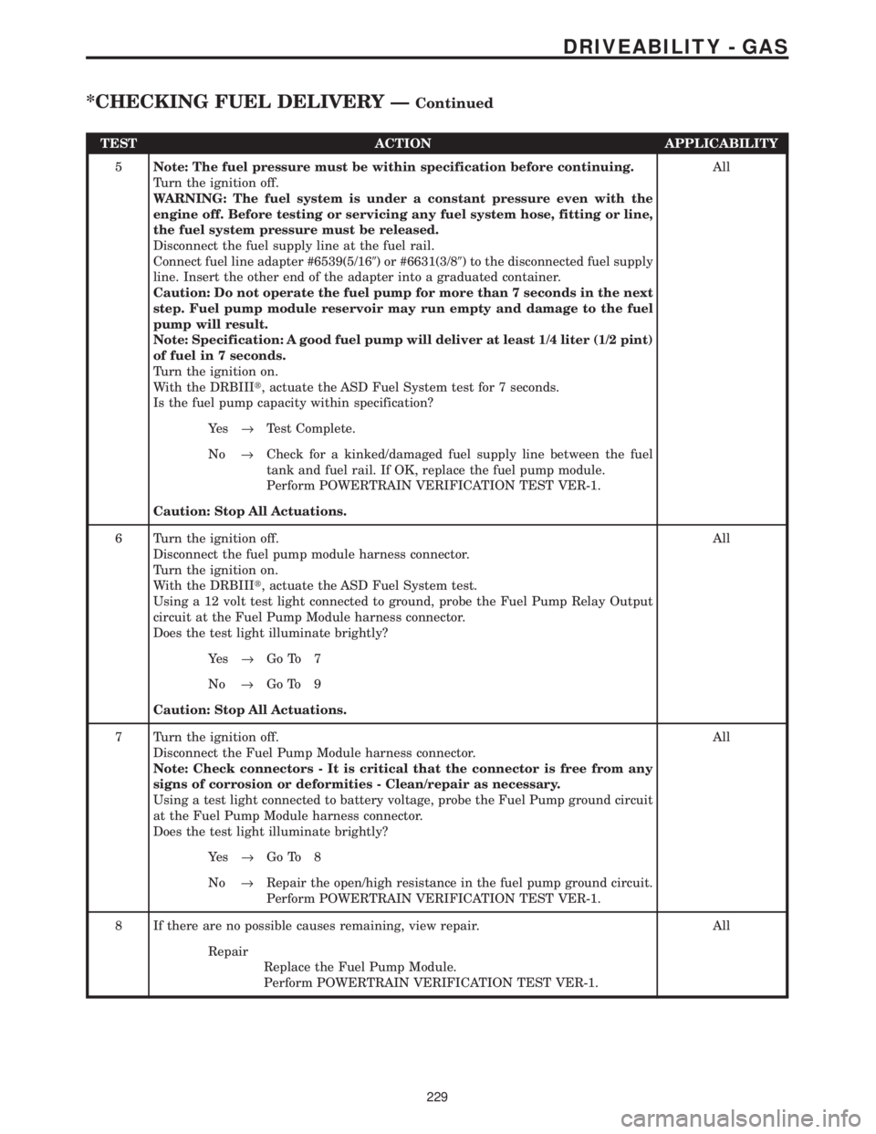
TEST ACTION APPLICABILITY
5Note: The fuel pressure must be within specification before continuing.
Turn the ignition off.
WARNING: The fuel system is under a constant pressure even with the
engine off. Before testing or servicing any fuel system hose, fitting or line,
the fuel system pressure must be released.
Disconnect the fuel supply line at the fuel rail.
Connect fuel line adapter #6539(5/169) or #6631(3/89) to the disconnected fuel supply
line. Insert the other end of the adapter into a graduated container.
Caution: Do not operate the fuel pump for more than 7 seconds in the next
step. Fuel pump module reservoir may run empty and damage to the fuel
pump will result.
Note: Specification: A good fuel pump will deliver at least 1/4 liter (1/2 pint)
of fuel in 7 seconds.
Turn the ignition on.
With the DRBIIIt, actuate the ASD Fuel System test for 7 seconds.
Is the fuel pump capacity within specification?All
Ye s®Test Complete.
No®Check for a kinked/damaged fuel supply line between the fuel
tank and fuel rail. If OK, replace the fuel pump module.
Perform POWERTRAIN VERIFICATION TEST VER-1.
Caution: Stop All Actuations.
6 Turn the ignition off.
Disconnect the fuel pump module harness connector.
Turn the ignition on.
With the DRBIIIt, actuate the ASD Fuel System test.
Using a 12 volt test light connected to ground, probe the Fuel Pump Relay Output
circuit at the Fuel Pump Module harness connector.
Does the test light illuminate brightly?All
Ye s®Go To 7
No®Go To 9
Caution: Stop All Actuations.
7 Turn the ignition off.
Disconnect the Fuel Pump Module harness connector.
Note: Check connectors - It is critical that the connector is free from any
signs of corrosion or deformities - Clean/repair as necessary.
Using a test light connected to battery voltage, probe the Fuel Pump ground circuit
at the Fuel Pump Module harness connector.
Does the test light illuminate brightly?All
Ye s®Go To 8
No®Repair the open/high resistance in the fuel pump ground circuit.
Perform POWERTRAIN VERIFICATION TEST VER-1.
8 If there are no possible causes remaining, view repair. All
Repair
Replace the Fuel Pump Module.
Perform POWERTRAIN VERIFICATION TEST VER-1.
229
DRIVEABILITY - GAS
*CHECKING FUEL DELIVERY ÐContinued
Page 4047 of 4284
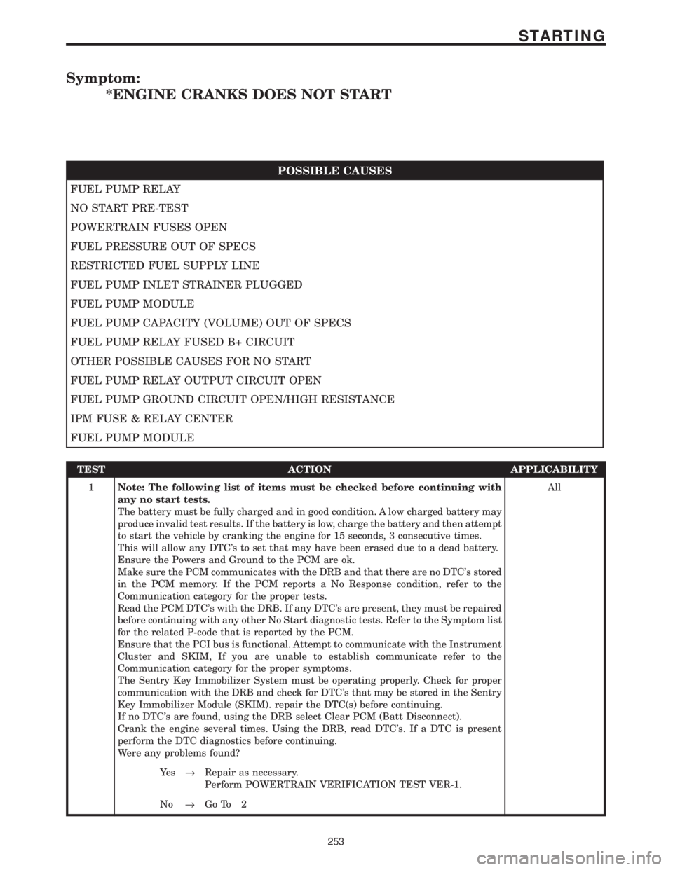
Symptom:
*ENGINE CRANKS DOES NOT START
POSSIBLE CAUSES
FUEL PUMP RELAY
NO START PRE-TEST
POWERTRAIN FUSES OPEN
FUEL PRESSURE OUT OF SPECS
RESTRICTED FUEL SUPPLY LINE
FUEL PUMP INLET STRAINER PLUGGED
FUEL PUMP MODULE
FUEL PUMP CAPACITY (VOLUME) OUT OF SPECS
FUEL PUMP RELAY FUSED B+ CIRCUIT
OTHER POSSIBLE CAUSES FOR NO START
FUEL PUMP RELAY OUTPUT CIRCUIT OPEN
FUEL PUMP GROUND CIRCUIT OPEN/HIGH RESISTANCE
IPM FUSE & RELAY CENTER
FUEL PUMP MODULE
TEST ACTION APPLICABILITY
1Note: The following list of items must be checked before continuing with
any no start tests.
The battery must be fully charged and in good condition. A low charged battery may
produce invalid test results. If the battery is low, charge the battery and then attempt
to start the vehicle by cranking the engine for 15 seconds, 3 consecutive times.
This will allow any DTC's to set that may have been erased due to a dead battery.
Ensure the Powers and Ground to the PCM are ok.
Make sure the PCM communicates with the DRB and that there are no DTC's stored
in the PCM memory. If the PCM reports a No Response condition, refer to the
Communication category for the proper tests.
Read the PCM DTC's with the DRB. If any DTC's are present, they must be repaired
before continuing with any other No Start diagnostic tests. Refer to the Symptom list
for the related P-code that is reported by the PCM.
Ensure that the PCI bus is functional. Attempt to communicate with the Instrument
Cluster and SKIM, If you are unable to establish communicate refer to the
Communication category for the proper symptoms.
The Sentry Key Immobilizer System must be operating properly. Check for proper
communication with the DRB and check for DTC's that may be stored in the Sentry
Key Immobilizer Module (SKIM). repair the DTC(s) before continuing.
If no DTC's are found, using the DRB select Clear PCM (Batt Disconnect).
Crank the engine several times. Using the DRB, read DTC's. If a DTC is present
perform the DTC diagnostics before continuing.
Were any problems found?All
Ye s®Repair as necessary.
Perform POWERTRAIN VERIFICATION TEST VER-1.
No®Go To 2
253
STARTING
Page 4123 of 4284
information at the time of publication. The right is
reserved to make changes at any time without
notice.
4.2.1 TECHNICIAN SAFETY INFORMATION
WARNING: ENGINES PRODUCE CARBON
MONOXIDE THAT IS ODORLESS, CAUSES
SLOWER REACTION TIMES AND CAN LEAD
TO SERIOUS INJURY. WHEN THE ENGINE IS
OPERATING, KEEP SERVICE AREAS WELL
VENTILATED OR ATTACH THE VEHICLE
EXHAUST SYSTEM TO THE SHOP EXHAUST
REMOVAL SYSTEM.
Some operations in this manual require that
hydraulic tubes, hoses, and fittings, disconnected
for inspection or testing purposes. These systems,
when fully charged contains fluid at high pressure.
Before disconnecting any hydraulic tubes, hoses or
fittings, be sure that the system is fully depressur-
ized.
When servicing a vehicle, always wear eye pro-
tection and remove any metal jewelry such as
watchbands or bracelets that might make an inad-
vertent electrical contact.
When diagnosing a transmission system problem,
it is important to follow approved procedures where
applicable. Following these procedures is very im-
portant to the safety of individuals performing
diagnostic tests.
4.2.2 VEHICLE PREPARATION FOR
TESTING
Make sure the vehicle being tested has a fully
charged battery. If it does not, false diagnostic codes
or error messages may occur. It is extremely impor-
tant that accurate shift lever position data be avail-
able to the TCM. The accuracy of any diagnostic
trouble code found in memory is doubtful unless the
Shift Lever Test, performed on the DRBtScan Tool,
passes.
4.2.3 SERVICING SUB-ASSEMBLIES
Some components of the powertrain system are
intended to be serviced in assembly only. Attempt-
ing to remove or repair certain system subcompo-
nents may result in personal injury and/or im-
proper system operation. Only those components
with approved repair and installation procedures in
the service instructions should be serviced.
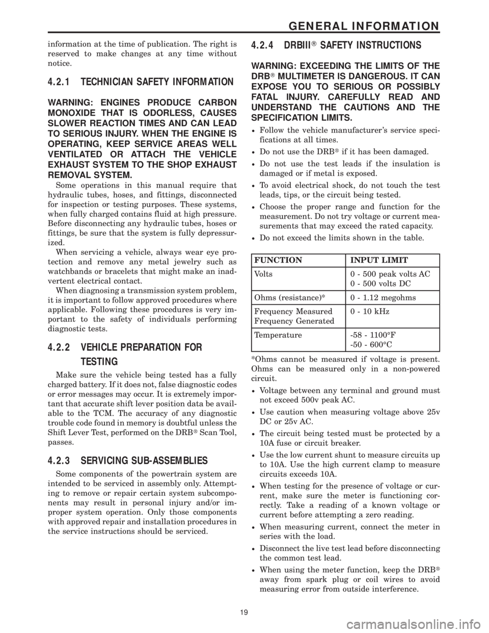
4.2.4 DRBIIITSAFETY INSTRUCTIONS
WARNING: EXCEEDING THE LIMITS OF THE
DRBTMULTIMETER IS DANGEROUS. IT CAN
EXPOSE YOU TO SERIOUS OR POSSIBLY
FATAL INJURY. CAREFULLY READ AND
UNDERSTAND THE CAUTIONS AND THE
SPECIFICATION LIMITS.
²Follow the vehicle manufacturer 's service speci-
fications at all times.
²Do not use the DRBtif it has been damaged.
²Do not use the test leads if the insulation is
damaged or if metal is exposed.
²To avoid electrical shock, do not touch the test
leads, tips, or the circuit being tested.
²Choose the proper range and function for the
measurement. Do not try voltage or current mea-
surements that may exceed the rated capacity.
²Do not exceed the limits shown in the table.
FUNCTION INPUT LIMIT
Volts 0 - 500 peak volts AC
0 - 500 volts DC
Ohms (resistance)* 0 - 1.12 megohms
Frequency Measured
Frequency Generated0-10kHz
Temperature -58 - 1100ÉF
-50 - 600ÉC
*Ohms cannot be measured if voltage is present.
Ohms can be measured only in a non-powered
circuit.
²Voltage between any terminal and ground must
not exceed 500v peak AC.
²Use caution when measuring voltage above 25v
DC or 25v AC.
²The circuit being tested must be protected by a
10A fuse or circuit breaker.
²Use the low current shunt to measure circuits up
to 10A. Use the high current clamp to measure
circuits exceeds 10A.
²When testing for the presence of voltage or cur-
rent, make sure the meter is functioning cor-
rectly. Take a reading of a known voltage or
current before attempting a zero reading.
²When measuring current, connect the meter in
series with the load.
²Disconnect the live test lead before disconnecting
the common test lead.
²When using the meter function, keep the DRBt
away from spark plug or coil wires to avoid
measuring error from outside interference.
19
GENERAL INFORMATION