2001 CHRYSLER VOYAGER air condition
[x] Cancel search: air conditionPage 880 of 4284

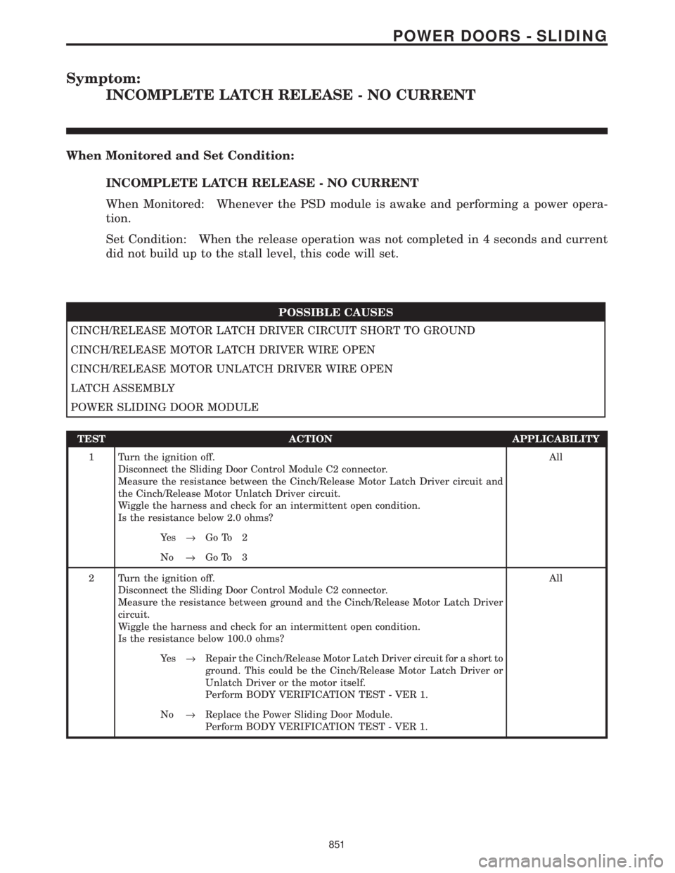
Symptom:
INCOMPLETE LATCH RELEASE - NO CURRENT
When Monitored and Set Condition:
INCOMPLETE LATCH RELEASE - NO CURRENT
When Monitored: Whenever the PSD module is awake and performing a power opera-
tion.
Set Condition: When the release operation was not completed in 4 seconds and current
did not build up to the stall level, this code will set.
POSSIBLE CAUSES
CINCH/RELEASE MOTOR LATCH DRIVER CIRCUIT SHORT TO GROUND
CINCH/RELEASE MOTOR LATCH DRIVER WIRE OPEN
CINCH/RELEASE MOTOR UNLATCH DRIVER WIRE OPEN
LATCH ASSEMBLY
POWER SLIDING DOOR MODULE
TEST ACTION APPLICABILITY
1 Turn the ignition off.
Disconnect the Sliding Door Control Module C2 connector.
Measure the resistance between the Cinch/Release Motor Latch Driver circuit and
the Cinch/Release Motor Unlatch Driver circuit.
Wiggle the harness and check for an intermittent open condition.
Is the resistance below 2.0 ohms?All
Ye s®Go To 2
No®Go To 3
2 Turn the ignition off.
Disconnect the Sliding Door Control Module C2 connector.
Measure the resistance between ground and the Cinch/Release Motor Latch Driver
circuit.
Wiggle the harness and check for an intermittent open condition.
Is the resistance below 100.0 ohms?All
Ye s®Repair the Cinch/Release Motor Latch Driver circuit for a short to
ground. This could be the Cinch/Release Motor Latch Driver or
Unlatch Driver or the motor itself.
Perform BODY VERIFICATION TEST - VER 1.
No®Replace the Power Sliding Door Module.
Perform BODY VERIFICATION TEST - VER 1.
851
POWER DOORS - SLIDING
Page 881 of 4284

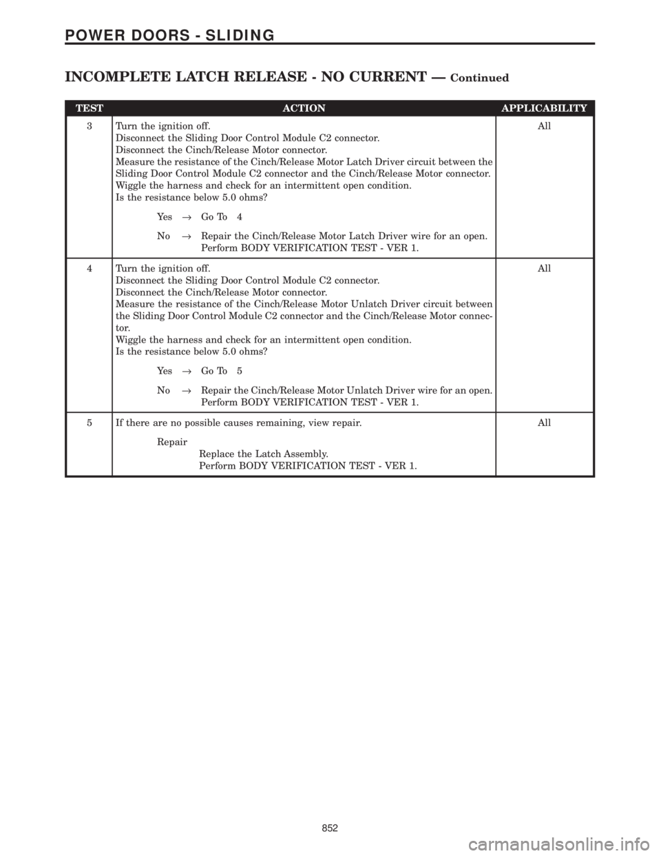
TEST ACTION APPLICABILITY
3 Turn the ignition off.
Disconnect the Sliding Door Control Module C2 connector.
Disconnect the Cinch/Release Motor connector.
Measure the resistance of the Cinch/Release Motor Latch Driver circuit between the
Sliding Door Control Module C2 connector and the Cinch/Release Motor connector.
Wiggle the harness and check for an intermittent open condition.
Is the resistance below 5.0 ohms?All
Ye s®Go To 4
No®Repair the Cinch/Release Motor Latch Driver wire for an open.
Perform BODY VERIFICATION TEST - VER 1.
4 Turn the ignition off.
Disconnect the Sliding Door Control Module C2 connector.
Disconnect the Cinch/Release Motor connector.
Measure the resistance of the Cinch/Release Motor Unlatch Driver circuit between
the Sliding Door Control Module C2 connector and the Cinch/Release Motor connec-
tor.
Wiggle the harness and check for an intermittent open condition.
Is the resistance below 5.0 ohms?All
Ye s®Go To 5
No®Repair the Cinch/Release Motor Unlatch Driver wire for an open.
Perform BODY VERIFICATION TEST - VER 1.
5 If there are no possible causes remaining, view repair. All
Repair
Replace the Latch Assembly.
Perform BODY VERIFICATION TEST - VER 1.
852
POWER DOORS - SLIDING
INCOMPLETE LATCH RELEASE - NO CURRENT ÐContinued
Page 895 of 4284

TEST ACTION APPLICABILITY
14 Disconnect the Sliding Door Control Module C2 connector.
Disconnect the Sliding Door Latch Sensing Switch connector.
Measure the resistance of the both Ground wires between the PSD C2 connector
(cavity 20) and the Sliding Door Latch Sensing Switch connector.
Wiggle the harness while observing the ohmmeter.
Is the resistance below 5.0 ohms in both ground wires at the switch connector?All
Ye s®Go To 15
No®Repair the Ground wire for an open.
Perform BODY VERIFICATION TEST - VER 1.
15 Disconnect the Sliding Door Control Module C2 connector.
Disconnect the Sliding Door Latch Sensing Switch connector (latch assembly).
Measure the resistance of the Sliding Door Ajar Switch Sense wire between the PSD
C2 connector and the Sliding Door Latch Sensing Switch connector.
Is the resistance below 5.0 ohms?All
Ye s®Go To 16
No®Repair the Sliding Door Ajar Switch Sense wire for an open.
Perform BODY VERIFICATION TEST - VER 1.
16 If there are no possible causes remaining, view repair. All
Repair
Replace the Ratchet Switch (latch assembly).
Perform BODY VERIFICATION TEST - VER 1.
17 Turn the ignition off.
Disconnect the Sliding Door Control Module C2 connector.
Measure the resistance between the Cinch/Release Motor Latch Driver circuit and
the Cinch/Release Motor Unlatch Driver circuit.
Wiggle the harness and check for an intermittent open condition.
Is the resistance below 2.0 ohms?All
Ye s®Go To 18
No®Go To 19
18 Turn the ignition off.
Disconnect the Sliding Door Control Module C2 connector.
Measure the resistance between ground and the Cinch/Release Motor Latch Driver
circuit.
Wiggle the harness and check for an intermittent open condition.
Is the resistance below 100.0 ohms?All
Ye s®Repair the Cinch/Release Motor Latch Driver circuit for a short to
ground. This could be the Cinch/Release Motor Latch Driver or
Unlatch Driver or the motor itself.
Perform BODY VERIFICATION TEST - VER 1.
No®Test Complete.
866
POWER DOORS - SLIDING
INCOMPLETE POWER CLOSE - LATCH FAILURE ÐContinued
Page 896 of 4284

TEST ACTION APPLICABILITY
19 Turn the ignition off.
Disconnect the Sliding Door Control Module C2 connector.
Disconnect the Cinch/Release Motor connector.
Measure the resistance of the Cinch/Release Motor Latch Driver circuit between the
Sliding Door Control Module C2 connector and the Cinch/Release Motor connector.
Wiggle the harness and check for an intermittent open condition.
Is the resistance below 5.0 ohms?All
Ye s®Go To 20
No®Repair the Cinch/Release Motor Latch Driver wire for an open.
Perform BODY VERIFICATION TEST - VER 1.
20 Turn the ignition off.
Disconnect the Sliding Door Control Module C2 connector.
Disconnect the Cinch/Release Motor connector.
Measure the resistance of the Cinch/Release Motor Unlatch Driver circuit between
the Sliding Door Control Module C2 connector and the Cinch/Release Motor connec-
tor.
Wiggle the harness and check for an intermittent open condition.
Is the resistance below 5.0 ohms?All
Ye s®Go To 21
No®Repair the Cinch/Release Motor Unlatch Driver wire for an open.
Perform BODY VERIFICATION TEST - VER 1.
21 If there are no possible causes remaining, view repair. All
Repair
Replace the Latch Assembly.
Perform BODY VERIFICATION TEST - VER 1.
867
POWER DOORS - SLIDING
INCOMPLETE POWER CLOSE - LATCH FAILURE ÐContinued
Page 901 of 4284

TEST ACTION APPLICABILITY
3 Turn the ignition off.
Disconnect the Sliding Door Control Module C1 connector.
Using a 12-volt test light connected to 12-volts, check the Ground circuit.
Wiggle the harness and check for an intermittent open condition.
Does the test light illuminate brightly?All
Ye s®Go To 4
No®Repair the Ground circuit for an open.
Perform BODY VERIFICATION TEST - VER 1.
4 Turn the ignition off.
Disconnect the Sliding Door Control Module C1 connector.
Measure the resistance between ground and the Sliding Door Close Driver circuit.
Wiggle the harness and check for an intermittent short circuit condition.
Is the resistance below 1000.0 ohms?All
Ye s®Repair the Sliding Door Close Driver circuit for a short to ground.
Perform BODY VERIFICATION TEST - VER 1.
No®Go To 5
5 Turn the ignition off.
Disconnect the Sliding Door Control Module C2 connector.
Measure the resistance between ground and the Cinch/Release Motor Unlatch Driver
circuit.
Wiggle the harness and check for an intermittent open condition.
Is the resistance below 1000.0 ohms?All
Ye s®Repair the Cinch/Release Motor Unlatch Driver circuit for a short
to ground.
Perform BODY VERIFICATION TEST - VER 1.
No®Go To 6
6 Turn the ignition off.
Disconnect the Sliding Door Control Module C2 connector.
Measure the resistance between ground and the Door Motor Clutch Driver circuit.
Wiggle the harness and check for an intermittent open condition.
Is the resistance below 5.0 ohms?All
Ye s®Repair the Door Motor Clutch Driver circuit for a short to ground.
Perform BODY VERIFICATION TEST - VER 1.
No®Go To 7
7 If there are no possible causes remaining, view repair. All
Repair
Replace the Power Sliding Door Motor/Clutch assembly.
Perform BODY VERIFICATION TEST - VER 1.
872
POWER DOORS - SLIDING
INCOMPLETE POWER CLOSE - OVERCURRENT ÐContinued
Page 908 of 4284

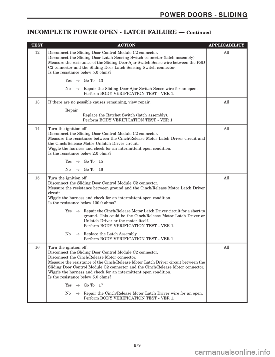
TEST ACTION APPLICABILITY
12 Disconnect the Sliding Door Control Module C2 connector.
Disconnect the Sliding Door Latch Sensing Switch connector (latch assembly).
Measure the resistance of the Sliding Door Ajar Switch Sense wire between the PSD
C2 connector and the Sliding Door Latch Sensing Switch connector.
Is the resistance below 5.0 ohms?All
Ye s®Go To 13
No®Repair the Sliding Door Ajar Switch Sense wire for an open.
Perform BODY VERIFICATION TEST - VER 1.
13 If there are no possible causes remaining, view repair. All
Repair
Replace the Ratchet Switch (latch assembly).
Perform BODY VERIFICATION TEST - VER 1.
14 Turn the ignition off.
Disconnect the Sliding Door Control Module C2 connector.
Measure the resistance between the Cinch/Release Motor Latch Driver circuit and
the Cinch/Release Motor Unlatch Driver circuit.
Wiggle the harness and check for an intermittent open condition.
Is the resistance below 2.0 ohms?All
Ye s®Go To 15
No®Go To 16
15 Turn the ignition off.
Disconnect the Sliding Door Control Module C2 connector.
Measure the resistance between ground and the Cinch/Release Motor Latch Driver
circuit.
Wiggle the harness and check for an intermittent open condition.
Is the resistance below 100.0 ohms?All
Ye s®Repair the Cinch/Release Motor Latch Driver circuit for a short to
ground. This could be the Cinch/Release Motor Latch Driver or
Unlatch Driver or the motor itself.
Perform BODY VERIFICATION TEST - VER 1.
No®Replace the Latch Assembly.
Perform BODY VERIFICATION TEST - VER 1.
16 Turn the ignition off.
Disconnect the Sliding Door Control Module C2 connector.
Disconnect the Cinch/Release Motor connector.
Measure the resistance of the Cinch/Release Motor Latch Driver circuit between the
Sliding Door Control Module C2 connector and the Cinch/Release Motor connector.
Wiggle the harness and check for an intermittent open condition.
Is the resistance below 5.0 ohms?All
Ye s®Go To 17
No®Repair the Cinch/Release Motor Latch Driver wire for an open.
Perform BODY VERIFICATION TEST - VER 1.
879
POWER DOORS - SLIDING
INCOMPLETE POWER OPEN - LATCH FAILURE ÐContinued
Page 909 of 4284

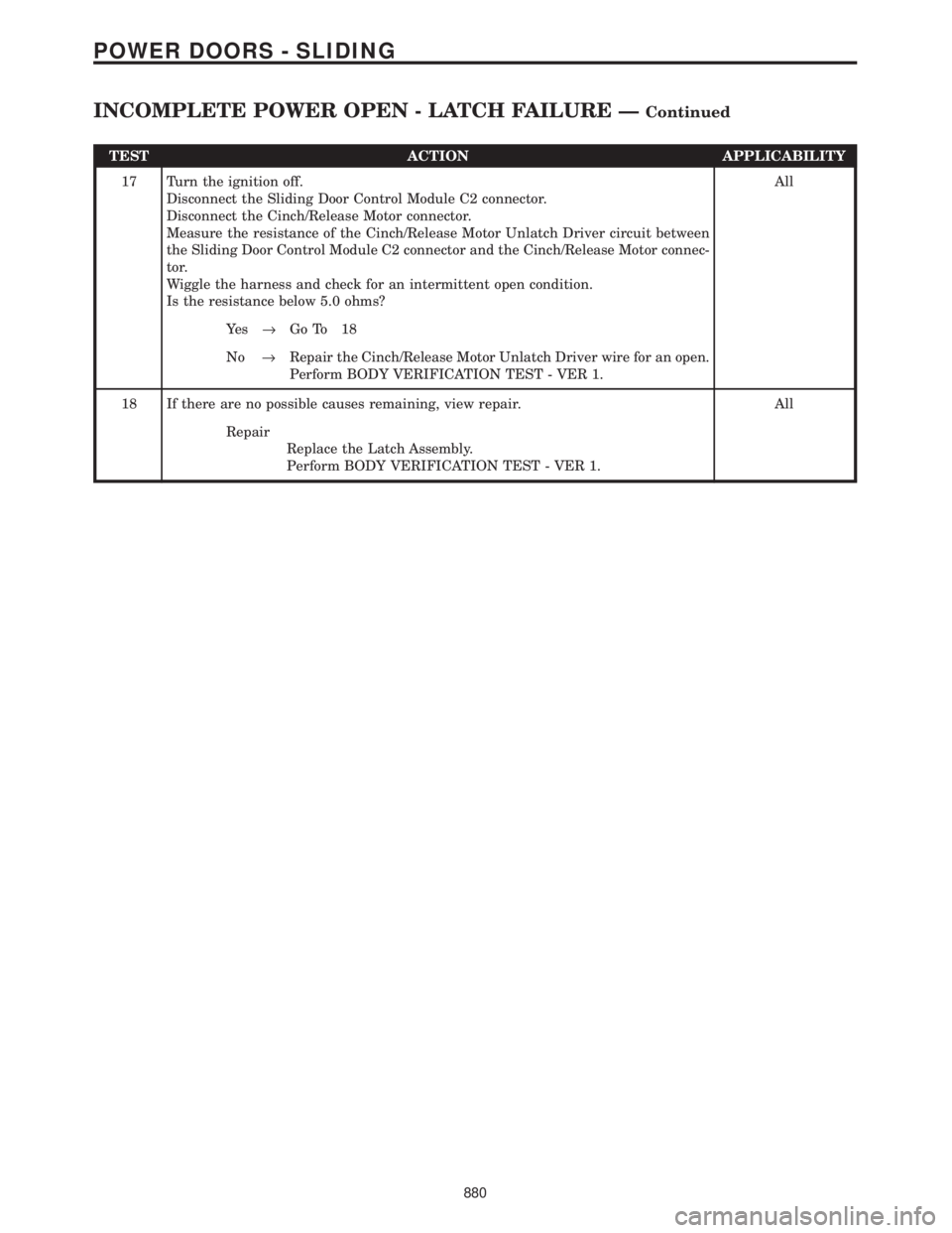
TEST ACTION APPLICABILITY
17 Turn the ignition off.
Disconnect the Sliding Door Control Module C2 connector.
Disconnect the Cinch/Release Motor connector.
Measure the resistance of the Cinch/Release Motor Unlatch Driver circuit between
the Sliding Door Control Module C2 connector and the Cinch/Release Motor connec-
tor.
Wiggle the harness and check for an intermittent open condition.
Is the resistance below 5.0 ohms?All
Ye s®Go To 18
No®Repair the Cinch/Release Motor Unlatch Driver wire for an open.
Perform BODY VERIFICATION TEST - VER 1.
18 If there are no possible causes remaining, view repair. All
Repair
Replace the Latch Assembly.
Perform BODY VERIFICATION TEST - VER 1.
880
POWER DOORS - SLIDING
INCOMPLETE POWER OPEN - LATCH FAILURE ÐContinued
Page 914 of 4284

TEST ACTION APPLICABILITY
3 Turn the ignition off.
Disconnect the Sliding Door Control Module C1 connector.
Using a 12-volt test light connected to 12-volts, check the Ground circuit.
Wiggle the harness and check for an intermittent open condition.
Does the test light illuminate brightly?All
Ye s®Go To 4
No®Repair the Ground circuit for an open.
Perform BODY VERIFICATION TEST - VER 1.
4 Turn the ignition off.
Disconnect the Sliding Door Control Module C1 connector.
Measure the resistance between ground and the Sliding Door Open Driver circuit.
Wiggle the harness and check for an intermittent short circuit condition.
Is the resistance below 1000.0 ohms?All
Ye s®Repair the Sliding Door Open Driver circuit for a short to ground.
Perform BODY VERIFICATION TEST - VER 1.
No®Go To 5
5 Turn the ignition off.
Disconnect the Sliding Door Control Module C2 connector.
Measure the resistance between the Cinch/Release Motor Latch Driver circuit and
the Cinch/Release Motor Unlatch Driver circuit.
Wiggle the harness and check for an intermittent open condition.
Is the resistance below 2.0 ohms?All
Ye s®Go To 6
No®Repair the Cinch/Release Motor Latch Driver circuit for an open.
Perform BODY VERIFICATION TEST - VER 1.
6 Turn the ignition off.
Disconnect the Sliding Door Control Module C2 connector.
Measure the resistance between ground and the Cinch/Release Motor Latch Driver
circuit.
Wiggle the harness and check for an intermittent short condition.
Is the resistance below 100.0 ohms?All
Ye s®Repair the Cinch/Release Motor Latch Driver circuit for a short to
ground.
Perform BODY VERIFICATION TEST - VER 1.
No®Go To 7
7 Turn the ignition off.
Disconnect the Sliding Door Control Module C2 connector.
Measure the resistance between ground and the Door Motor Clutch Driver circuit.
Wiggle the harness and check for an intermittent short condition.
Is the resistance below 100.0 ohms?All
Ye s®Repair the Door Motor Clutch Driver circuit for a short to ground.
Perform BODY VERIFICATION TEST - VER 1.
No®Go To 8
8 If there are no possible causes remaining, view repair. All
Repair
Replace the Power Sliding Door Motor/Clutch assembly.
Perform BODY VERIFICATION TEST - VER 1.
885
POWER DOORS - SLIDING
INCOMPLETE POWER OPEN - OVERCURRENT ÐContinued