2001 CHRYSLER VOYAGER tow bar
[x] Cancel search: tow barPage 3537 of 4284
INSTALLATION
NOTE: The screws attaching the door latch to the
door end frame have nylon patches on the threads.
All screws must be replaced when the latch has
been removed.
(1) Place door latch in position on door end frame.
(2) Install screws attaching door latch to door end
frame. Tighten screws to 10 N´m (90 in. lbs.) torque.
(3) Insert linkage into door latch.
(4) Engage clips attaching linkage to door latch.
(5) Connect wire connector into power door lock
motor, if equipped.
(6) Insert a hex wrench through the elongated hole
located in the door shut face above the latch.
(7) Loosen allen head screw.
(8) Pull outward on the outside door handle and
release.
(9) Tighten allen head screw.
(10)
Verify door latch and power door lock operation.
(11) Install watershield and front door trim panel.
LATCH STRIKER
REMOVAL
(1) Mark outline of door striker on B-pillar to aid
in installation.
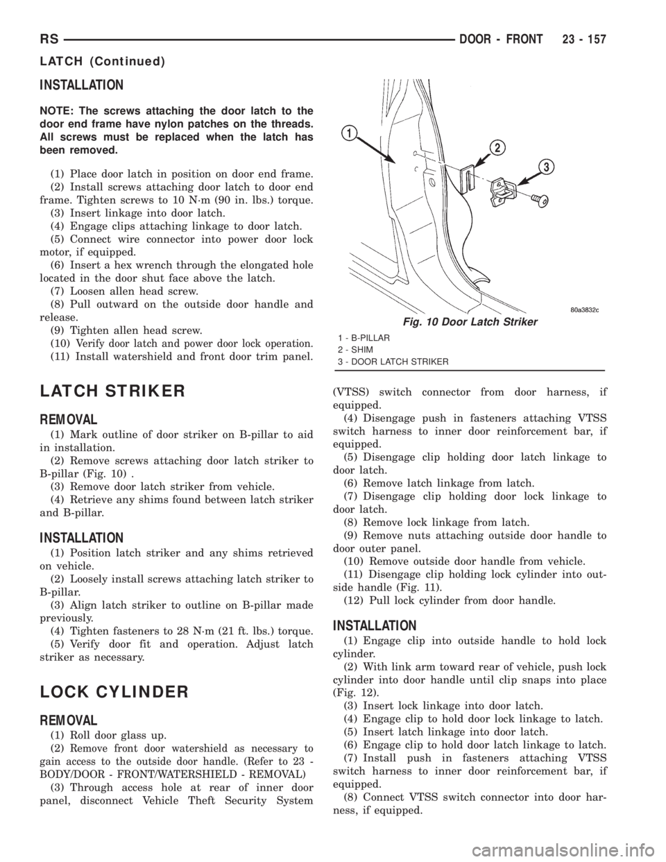
(2) Remove screws attaching door latch striker to
B-pillar (Fig. 10) .
(3) Remove door latch striker from vehicle.
(4) Retrieve any shims found between latch striker
and B-pillar.
INSTALLATION
(1) Position latch striker and any shims retrieved
on vehicle.
(2) Loosely install screws attaching latch striker to
B-pillar.
(3) Align latch striker to outline on B-pillar made
previously.
(4) Tighten fasteners to 28 N´m (21 ft. lbs.) torque.
(5) Verify door fit and operation. Adjust latch
striker as necessary.
LOCK CYLINDER
REMOVAL
(1) Roll door glass up.
(2)
Remove front door watershield as necessary to
gain access to the outside door handle. (Refer to 23 -
BODY/DOOR - FRONT/WATERSHIELD - REMOVAL)
(3) Through access hole at rear of inner door
panel, disconnect Vehicle Theft Security System(VTSS) switch connector from door harness, if
equipped.
(4) Disengage push in fasteners attaching VTSS
switch harness to inner door reinforcement bar, if
equipped.
(5) Disengage clip holding door latch linkage to
door latch.
(6) Remove latch linkage from latch.
(7) Disengage clip holding door lock linkage to
door latch.
(8) Remove lock linkage from latch.
(9) Remove nuts attaching outside door handle to
door outer panel.
(10) Remove outside door handle from vehicle.
(11) Disengage clip holding lock cylinder into out-
side handle (Fig. 11).
(12) Pull lock cylinder from door handle.
INSTALLATION
(1) Engage clip into outside handle to hold lock
cylinder.
(2) With link arm toward rear of vehicle, push lock
cylinder into door handle until clip snaps into place
(Fig. 12).
(3) Insert lock linkage into door latch.
(4) Engage clip to hold door lock linkage to latch.
(5) Insert latch linkage into door latch.
(6) Engage clip to hold door latch linkage to latch.
(7) Install push in fasteners attaching VTSS
switch harness to inner door reinforcement bar, if
equipped.
(8) Connect VTSS switch connector into door har-
ness, if equipped.
Fig. 10 Door Latch Striker
1 - B-PILLAR
2 - SHIM
3 - DOOR LATCH STRIKER
RSDOOR - FRONT23 - 157
LATCH (Continued)
Page 3576 of 4284
INSTALLATION
NOTE: The crossbar assemblies are designed to be
installed in only one way. Check top and bottom
surfaces of the crossbar for the word FRONT and
directional arrows. The directional arrows must
point toward the front of the vehicle.
(1) Place crossbar in position on vehicle.
(2) Work from side to side sliding the crossbar
assembly back a little at a time to ensure it remains
perpendicular to the side rails.
(3) Position first crossbar assembly crossbar at the
second most rearward locator holes. Press the top of
the stanchion lever to lock it into position.
(4) Position the second crossbar assembly in the
second hole from the front. Lock into place.
(5) Place luggage rack riser into position.
(6) Install two fasteners into riser. Tighten fasten-
ers to 4 mm (35 in. lbs.) torque.
REAR QUARTER PANEL/
FENDER AIR EXHAUSTER
DESCRIPTION
Air exhausters, designed to conform to the body
structure, allow air entering at the front of the vehi-
cle to flow out the back. By reducing air pressure
within the vehicle, the exhausters also reduce blower
noise at any given air flow level compared to operat-
ing without them and help reduce door closing effort.
They are located in the lower rear comers of the
body.
REMOVAL
SHORT WHEELBASE
(1) Remove the rear fascia from the body. (Refer to
13 - FRAMES & BUMPERS/BUMPERS/REAR FAS-
CIA - REMOVAL).
(2) Using a trim stick or another suitable wide flat
bladed tool, carefully pry the air exhauster away
from the opening in the lower aperture panel until
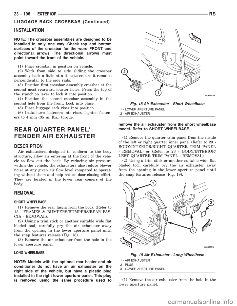
the snap features release (Fig. 18).
(3) Remove the air exhauster from the hole in the
lower aperture panel.
LONG WHEELBASE
NOTE: Models with the optional rear heater and air
conditioner do not have an air exhauster on the
right side of the vehicle, but have a plastic plug
installed in the right lower aperture panel. This plug
is removed using the same procedure used toremove the air exhauster from the short wheelbase
model. Refer to SHORT WHEELBASE .
(1) Remove the quarter trim panel from the inside
of the left or right quarter inner panel (Refer to 23 -
BODY/INTERIOR/RIGHT QUARTER TRIM PANEL
- REMOVAL) or (Refer to 23 - BODY/INTERIOR/
LEFT QUARTER TRIM PANEL - REMOVAL).
(2) Using a trim stick or another suitable wide flat
bladed tool, carefully pry the air exhauster away
from the opening in the lower aperture panel until
the snap features release (Fig. 19).
(1) Remove the air exhauster from the hole in the
lower aperture panel.
Fig. 18 Air Exhauster - Short Wheelbase
1 - LOWER APERTURE PANEL
2 - AIR EXHAUSTER
Fig. 19 Air Exhauster - Long Wheelbase
1 - AIR EXHAUSTER
2 - PLUG
3 - LOWER APERTURE PANEL
23 - 196 EXTERIORRS
LUGGAGE RACK CROSSBAR (Continued)
Page 3581 of 4284
(4) Align hood latch by placing latch over net
pierced tabs. If alignment is required, flatten or
grind tabs.
(5) Verify hood operation and alignment. Adjust as
necessary.
(6) Tighten attaching bolts to 13.5 N´m (10 ft. lbs.)
torque.
LATCH RELEASE CABLE
REMOVAL
(1) Remove hood latch.
(2) Disengage cable end from hood latch locking
mechanism.
(3) Slide cable case end sideways in keyhole slot of
hood latch while pinching barb on cable case closed.
(4) Remove cable from latch (Fig. 4).
(5) Remove hood release handle from instrument
panel.
(6) Disengage rubber grommet cable insulator
from hole in dash panel.
(7) Attach a suitable length of mechanic's wire to
latch end of cable to assist cable installation.
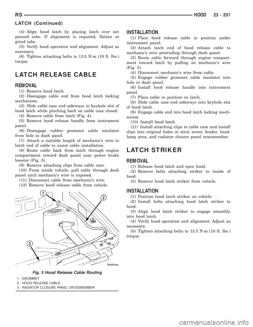
(8) Route cable back from latch through engine
compartment toward dash panel near power brake
booster (Fig. 5).
(9) Remove attaching clips from cable case.
(10) From inside vehicle, pull cable through dash
panel until mechanic's wire is exposed.
(11) Disconnect cable from mechanic's wire.
(12) Remove hood release cable from vehicle.
INSTALLATION
(1) Place hood release cable in position under
instrument panel.
(2) Attach latch end of hood release cable to
mechanic's wire protruding through dash panel.
(3) Route cable forward through engine compart-
ment toward latch by pulling on mechanic's wire
(Fig. 5).
(4) Disconnect mechanic's wire from cable.
(5) Engage rubber grommet cable insulator into
hole in dash panel.
(6) Install hood release handle into instrument
panel.
(7) Place cable in position on latch.
(8) Slide cable case end sideways into keyhole slot
of hood latch.
(9) Engage cable end into hood latch locking mech-
anism.
(10) Install hood latch.
(11) Install attaching clips to cable case and install
clips into original holes in strut tower, fender, head-
lamp area, and radiator closure panel crossmember.
LATCH STRIKER
REMOVAL
(1) Release hood latch and open hood.
(2) Remove bolts attaching striker to inside of
hood.
(3) Remove hood latch striker from vehicle.
INSTALLATION
(1) Position hood latch striker on vehicle.
(2) Install bolts attaching hood latch striker to
hood.
(3) Align hood latch striker to engage smoothly
into hood latch.
(4) Verify hood operation and alignment. Adjust as
necessary.
(5) Tighten attaching bolts to 13.5 N´m (10 ft. lbs.)
torque.
Fig. 5 Hood Release Cable Routing
1 - GROMMET
2 - HOOD RELEASE CABLE
3 - RADIATOR CLOSURE PANEL CROSSMEMBER
RSHOOD23 - 201
LATCH (Continued)
Page 3712 of 4284
it is engaged on the nipple and peel the hose off of
the nipple. This method of removal will require
heater hose replacement.
INSTALLATION
There are several heater core plumbing configura-
tions used on this model, depending upon the engine
size and other optional equipment. One plumbing
configuration is used for all 2.4L engines (Fig. 21),
while the 3.3L and 3.8L engines have unique heater
return plumbing on the engine for models with or
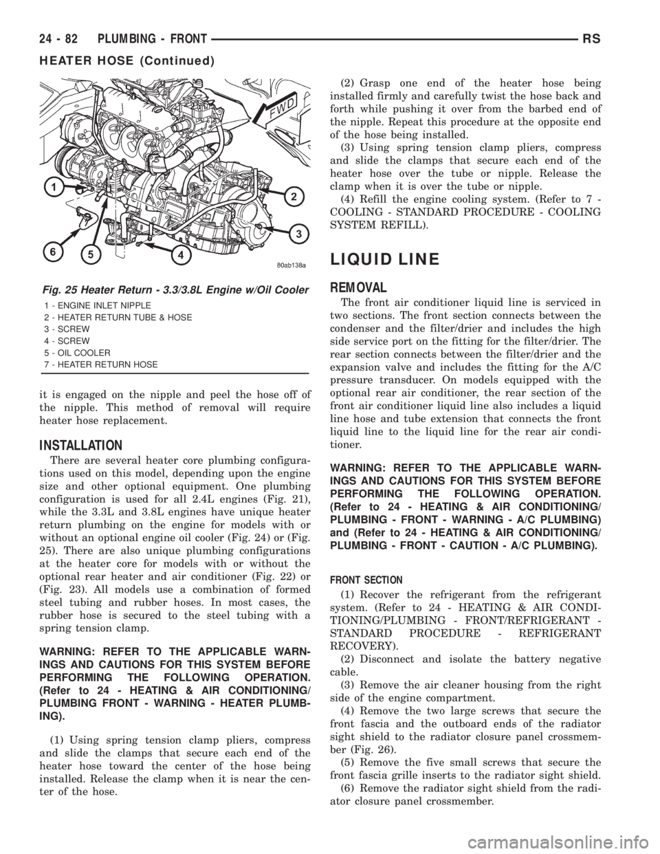
without an optional engine oil cooler (Fig. 24) or (Fig.
25). There are also unique plumbing configurations
at the heater core for models with or without the
optional rear heater and air conditioner (Fig. 22) or
(Fig. 23). All models use a combination of formed
steel tubing and rubber hoses. In most cases, the
rubber hose is secured to the steel tubing with a
spring tension clamp.
WARNING: REFER TO THE APPLICABLE WARN-
INGS AND CAUTIONS FOR THIS SYSTEM BEFORE
PERFORMING THE FOLLOWING OPERATION.
(Refer to 24 - HEATING & AIR CONDITIONING/
PLUMBING FRONT - WARNING - HEATER PLUMB-
ING).
(1) Using spring tension clamp pliers, compress
and slide the clamps that secure each end of the
heater hose toward the center of the hose being
installed. Release the clamp when it is near the cen-
ter of the hose.(2) Grasp one end of the heater hose being
installed firmly and carefully twist the hose back and
forth while pushing it over from the barbed end of
the nipple. Repeat this procedure at the opposite end
of the hose being installed.
(3) Using spring tension clamp pliers, compress
and slide the clamps that secure each end of the
heater hose over the tube or nipple. Release the
clamp when it is over the tube or nipple.
(4) Refill the engine cooling system. (Refer to 7 -
COOLING - STANDARD PROCEDURE - COOLING
SYSTEM REFILL).
LIQUID LINE
REMOVAL
The front air conditioner liquid line is serviced in
two sections. The front section connects between the
condenser and the filter/drier and includes the high
side service port on the fitting for the filter/drier. The
rear section connects between the filter/drier and the
expansion valve and includes the fitting for the A/C
pressure transducer. On models equipped with the
optional rear air conditioner, the rear section of the
front air conditioner liquid line also includes a liquid
line hose and tube extension that connects the front
liquid line to the liquid line for the rear air condi-
tioner.
WARNING: REFER TO THE APPLICABLE WARN-
INGS AND CAUTIONS FOR THIS SYSTEM BEFORE
PERFORMING THE FOLLOWING OPERATION.
(Refer to 24 - HEATING & AIR CONDITIONING/
PLUMBING - FRONT - WARNING - A/C PLUMBING)
and (Refer to 24 - HEATING & AIR CONDITIONING/
PLUMBING - FRONT - CAUTION - A/C PLUMBING).
FRONT SECTION
(1) Recover the refrigerant from the refrigerant
system. (Refer to 24 - HEATING & AIR CONDI-
TIONING/PLUMBING - FRONT/REFRIGERANT -
STANDARD PROCEDURE - REFRIGERANT
RECOVERY).
(2) Disconnect and isolate the battery negative
cable.
(3) Remove the air cleaner housing from the right
side of the engine compartment.
(4) Remove the two large screws that secure the
front fascia and the outboard ends of the radiator
sight shield to the radiator closure panel crossmem-
ber (Fig. 26).
(5) Remove the five small screws that secure the
front fascia grille inserts to the radiator sight shield.
(6) Remove the radiator sight shield from the radi-
ator closure panel crossmember.
Fig. 25 Heater Return - 3.3/3.8L Engine w/Oil Cooler
1 - ENGINE INLET NIPPLE
2 - HEATER RETURN TUBE & HOSE
3 - SCREW
4 - SCREW
5 - OIL COOLER
7 - HEATER RETURN HOSE
24 - 82 PLUMBING - FRONTRS
HEATER HOSE (Continued)
Page 3733 of 4284
CAUTION:
When removing hoses from outlet nipples, do not
use excessive force. Outlet nipples may become
damaged and leak engine coolant.
(4) Compress insert in rear heater hose quick con-
nection and pull downward on hose. (Fig. 12)
(5) Remove (3) straps securing underbody lines.
(Fig. 9)
(6) Separate and remove rear heater lines from
vehicle.
INSTALLATION
There are several heater core plumbing configura-
tions used on this model, depending upon the engine
size and other optional equipment. One plumbing
configuration is used for all 2.4L engines (Fig. 21),
while the 3.3L and 3.8L engines have unique heater
return plumbing on the engine for models with or
without an optional engine oil cooler (Fig. 24) or (Fig.
25). There are also unique plumbing configurations
at the heater core for models with or without the
optional rear heater and air conditioner (Fig. 22) or
(Fig. 23). All models use a combination of formed
steel tubing and rubber hoses. In most cases, the
rubber hose is secured to the steel tubing with a
spring tension clamp.
WARNING: REFER TO THE APPLICABLE WARN-
INGS AND CAUTIONS FOR THIS SYSTEM BEFORE
PERFORMING THE FOLLOWING OPERATION.
(Refer to 24 - HEATING & AIR CONDITIONING/
PLUMBING FRONT - WARNING - HEATER PLUMB-
ING).
(1) Using spring tension clamp pliers, compress
and slide the clamps that secure each end of the
heater hose toward the center of the hose being
installed. Release the clamp when it is near the cen-
ter of the hose.
(2) Grasp one end of the heater hose being
installed firmly and carefully twist the hose back and
forth while pushing it over from the barbed end of
the nipple. Repeat this procedure at the opposite end
of the hose being installed.
(3) Using spring tension clamp pliers, compress
and slide the clamps that secure each end of the
heater hose over the tube or nipple. Release the
clamp when it is over the tube or nipple.
(4) Refill the engine cooling system. (Refer to 7 -
COOLING - STANDARD PROCEDURE - COOLING
SYSTEM REFILL).
SUCTION LINE
REMOVAL
The front air conditioner suction line includes the
low side service port on a section of tubing located
near the compressor. On models equipped with the
optional rear air conditioner, the front air conditioner
suction line also includes a suction line hose and
tube extension that connects the front suction line to
the suction line for the rear air conditioner.
WARNING: REFER TO THE APPLICABLE WARN-
INGS AND CAUTIONS FOR THIS SYSTEM BEFORE
PERFORMING THE FOLLOWING OPERATION.
(Refer to 24 - HEATING & AIR CONDITIONING/
PLUMBING - FRONT - WARNING - A/C PLUMBING)
and (Refer to 24 - HEATING & AIR CONDITIONING/
PLUMBING - FRONT - CAUTION - A/C PLUMBING).
(1) Recover the refrigerant from the refrigerant
system. (Refer to 24 - HEATING & AIR CONDI-
TIONING/PLUMBING - FRONT/REFRIGERANT -
STANDARD PROCEDURE - REFRIGERANT
RECOVERY).
(2) Disconnect and isolate the battery negative
cable.
(3) Remove the air cleaner top cover and snorkel
from the air cleaner housing located on the right side
of the engine compartment.
(4) Disconnect the drain tube from the wiper mod-
ule drain on the right side of the engine compart-
ment.
(5) Remove the nut that secures the suction line
fitting to the top of the compressor.
(6) Disconnect the suction line fitting from the
compressor suction port.
(7) Remove the seal from the suction line fitting
and discard.
(8) Install plugs in, or tape over the opened suc-
tion line fitting and the compressor suction port.
(9) Disengage the retainer that secures the suction
line routing clip to the filter-drier mounting bracket
on the side of the right front strut tower in the
engine compartment (Fig. 7).
(10) Remove the nut that secures the suction line
and liquid line fittings to the expansion valve.
(11) Disconnect the suction line and liquid line fit-
tings from the expansion valve.
(12) Remove the seals from the suction line and
liquid line fittings and discard.
(13) Install plugs in, or tape over the opened suc-
tion line and liquid line fittings and both expansion
valve ports.
(14) If the vehicle is equipped with the optional
rear air conditioner, go to Step 15. If the vehicle does
RSPLUMBING - REAR24 - 103
HEATER HOSE (Continued)