2001 CHRYSLER VOYAGER brake pads
[x] Cancel search: brake padsPage 1673 of 4284
STANDARD PROCEDURE - BRAKE ROTOR
MACHINING
NOTE: Refacing the rotor is not required each time
the brake pads are replaced, only when the need is
foreseen.
Any servicing of the rotor requires extreme care to
maintain the rotor within service tolerances to
ensure proper brake action.
If the rotor surface is deeply scored or warped, or
there is a complaint of brake roughness or brake
pedal pulsation, the rotor should be refaced using a
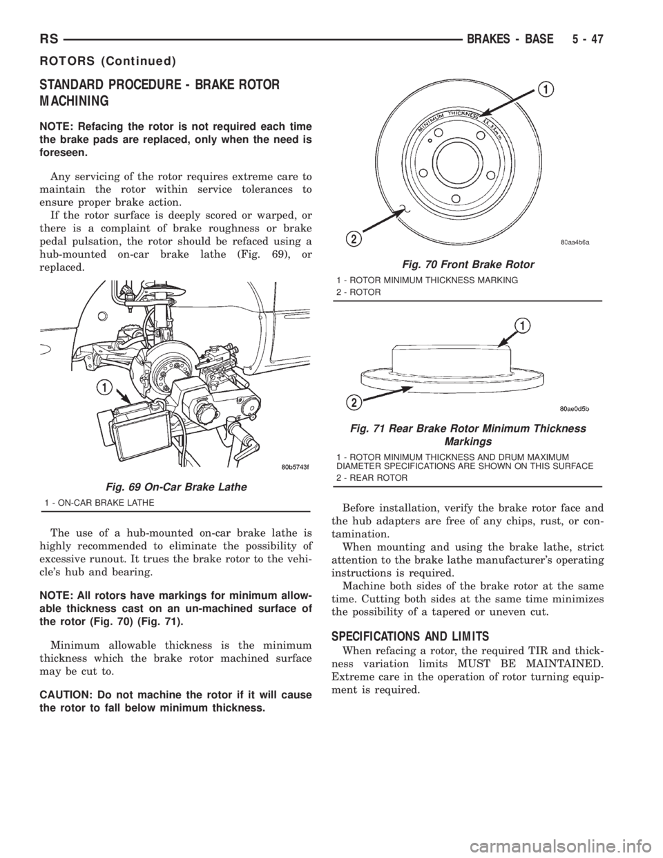
hub-mounted on-car brake lathe (Fig. 69), or
replaced.
The use of a hub-mounted on-car brake lathe is
highly recommended to eliminate the possibility of
excessive runout. It trues the brake rotor to the vehi-
cle's hub and bearing.
NOTE: All rotors have markings for minimum allow-
able thickness cast on an un-machined surface of
the rotor (Fig. 70) (Fig. 71).
Minimum allowable thickness is the minimum
thickness which the brake rotor machined surface
may be cut to.
CAUTION: Do not machine the rotor if it will cause
the rotor to fall below minimum thickness.Before installation, verify the brake rotor face and
the hub adapters are free of any chips, rust, or con-
tamination.
When mounting and using the brake lathe, strict
attention to the brake lathe manufacturer's operating
instructions is required.
Machine both sides of the brake rotor at the same
time. Cutting both sides at the same time minimizes
the possibility of a tapered or uneven cut.
SPECIFICATIONS AND LIMITS
When refacing a rotor, the required TIR and thick-
ness variation limits MUST BE MAINTAINED.
Extreme care in the operation of rotor turning equip-
ment is required.
Fig. 69 On-Car Brake Lathe
1 - ON-CAR BRAKE LATHE
Fig. 70 Front Brake Rotor
1 - ROTOR MINIMUM THICKNESS MARKING
2 - ROTOR
Fig. 71 Rear Brake Rotor Minimum Thickness
Markings
1 - ROTOR MINIMUM THICKNESS AND DRUM MAXIMUM
DIAMETER SPECIFICATIONS ARE SHOWN ON THIS SURFACE
2 - REAR ROTOR
RSBRAKES - BASE5-47
ROTORS (Continued)
Page 1675 of 4284
out of master cylinder when brake tube is remove
from wheel cylinder.
(2) Raise vehicle. (Refer to LUBRICATION &
MAINTENANCE/HOISTING - STANDARD PROCE-
DURE).
(3) Remove wheel and tire assembly.
(4) Disconnect brake tube from rear of wheel cylin-
der. Cap open ends
(5) Remove brake drum.
(6) Remove brake shoes from brake support plate.
(Refer to 5 - BRAKES/HYDRAULIC/MECHANICAL/
BRAKE PADS/SHOES - REMOVAL).
(7) Remove the 2 bolts attaching the wheel cylin-
der to the brake support plate.
(8) Remove the wheel cylinder from the brake sup-
port plate.
(9) Disconnect the park brake cable from the park
brake actuation lever.
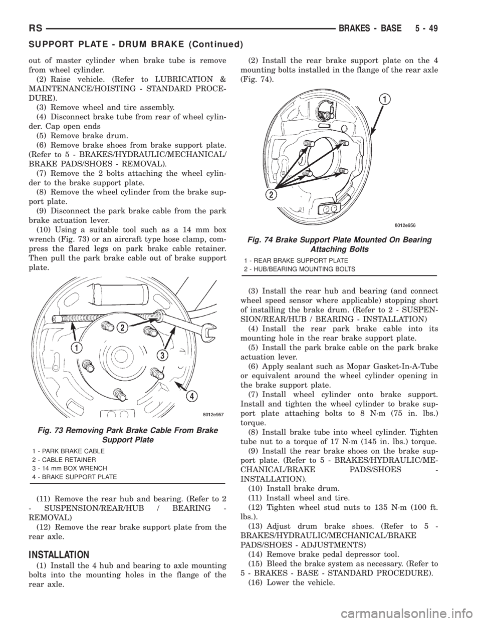
(10) Using a suitable tool such as a 14 mm box
wrench (Fig. 73) or an aircraft type hose clamp, com-
press the flared legs on park brake cable retainer.
Then pull the park brake cable out of brake support
plate.
(11) Remove the rear hub and bearing. (Refer to 2
- SUSPENSION/REAR/HUB / BEARING -
REMOVAL)
(12) Remove the rear brake support plate from the
rear axle.
INSTALLATION
(1) Install the 4 hub and bearing to axle mounting
bolts into the mounting holes in the flange of the
rear axle.(2) Install the rear brake support plate on the 4
mounting bolts installed in the flange of the rear axle
(Fig. 74).
(3) Install the rear hub and bearing (and connect
wheel speed sensor where applicable) stopping short
of installing the brake drum. (Refer to 2 - SUSPEN-
SION/REAR/HUB / BEARING - INSTALLATION)
(4) Install the rear park brake cable into its
mounting hole in the rear brake support plate.
(5) Install the park brake cable on the park brake
actuation lever.
(6) Apply sealant such as Mopar Gasket-In-A-Tube
or equivalent around the wheel cylinder opening in
the brake support plate.
(7) Install wheel cylinder onto brake support.
Install and tighten the wheel cylinder to brake sup-
port plate attaching bolts to 8 N´m (75 in. lbs.)
torque.
(8) Install brake tube into wheel cylinder. Tighten
tube nut to a torque of 17 N´m (145 in. lbs.) torque.
(9) Install the rear brake shoes on the brake sup-
port plate. (Refer to 5 - BRAKES/HYDRAULIC/ME-
CHANICAL/BRAKE PADS/SHOES -
INSTALLATION).
(10) Install brake drum.
(11) Install wheel and tire.
(12) Tighten wheel stud nuts to 135 N´m (100 ft.
lbs.).
(13) Adjust drum brake shoes. (Refer to 5 -
BRAKES/HYDRAULIC/MECHANICAL/BRAKE
PADS/SHOES - ADJUSTMENTS)
(14) Remove brake pedal depressor tool.
(15) Bleed the brake system as necessary. (Refer to
5 - BRAKES - BASE - STANDARD PROCEDURE).
(16) Lower the vehicle.
Fig. 73 Removing Park Brake Cable From Brake
Support Plate
1 - PARK BRAKE CABLE
2 - CABLE RETAINER
3 - 14 mm BOX WRENCH
4 - BRAKE SUPPORT PLATE
Fig. 74 Brake Support Plate Mounted On Bearing
Attaching Bolts
1 - REAR BRAKE SUPPORT PLATE
2 - HUB/BEARING MOUNTING BOLTS
RSBRAKES - BASE5-49
SUPPORT PLATE - DRUM BRAKE (Continued)
Page 1676 of 4284
WHEEL CYLINDERS
REMOVAL
(1) Using a brake pedal depressor, move and
secure brake pedal to a position past its first 1 inch
of travel. This will prevent brake fluid from draining
out of master cylinder when brake tube is remove
from wheel cylinder.
(2) Raise vehicle. (Refer to LUBRICATION &
MAINTENANCE/HOISTING - STANDARD PROCE-
DURE).
(3) Remove wheel and tire assembly.
(4) Disconnect brake tube from rear of wheel cylin-
der. Cap open ends
(5) Remove brake drum.
(6) Remove brake shoes from brake support plate
(Discard if contaminated).(Refer to 5 - BRAKES/HY-
DRAULIC/MECHANICAL/BRAKE PADS/SHOES -
REMOVAL)
(7) Remove the 2 bolts attaching the wheel cylin-
der to the brake support plate.
(8) Remove the wheel cylinder from the brake sup-
port plate.
INSPECTION
With brake drums removed, inspect the wheel cyl-
inder boots for evidence of a brake fluid leak. Visu-
ally check the boots for cuts, tears, or heat cracks. If
any of these conditions exist, the wheel cylinders
should be completely cleaned, inspected and new
parts installed.
If a wheel cylinder is leaking and the brake lining
material is saturated with brake fluid, the brake
shoes must be replaced.
INSTALLATION
(1) Apply sealant such as Mopar Gasket-In-A-Tube
or equivalent around the wheel cylinder opening in
the brake support plate.
(2) Install wheel cylinder onto brake support.
Install and tighten the wheel cylinder to brake sup-
port plate attaching bolts to 8 N´m (75 in. lbs.)
torque.
(3) Install brake tube into wheel cylinder. Tighten
tube nut to a torque of 17 N´m (145 in. lbs.) torque.
(4) Install the rear brake shoes on the brake sup-
port plate. (Refer to 5 - BRAKES/HYDRAULIC/ME-
CHANICAL/BRAKE PADS/SHOES -
INSTALLATION).
(5) Install brake drum.
(6) Install wheel and tire. Install and tighten
wheel lug nuts to 135 N´m (100 ft. lbs.).
(7) Adjust drum brake shoes. (Refer to 5 -
BRAKES/HYDRAULIC/MECHANICAL/BRAKE
PADS/SHOES - ADJUSTMENTS)
(8) Remove brake pedal depressor tool.(9) Bleed the brake system as necessary. (Refer to
5 - BRAKES - BASE - STANDARD PROCEDURE).
(10) Lower vehicle.
PARKING BRAKE
DESCRIPTION
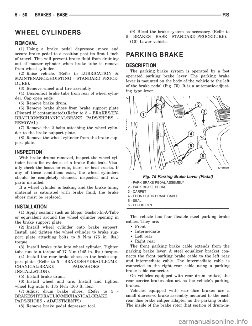
The parking brake system is operated by a foot
operated parking brake lever. The parking brake
lever is mounted on the body of the vehicle to the left
of the brake pedal (Fig. 75). It is a automatic-adjust-
ing type lever.
The vehicle has four flexible steel parking brake
cables. They are:
²Front
²Intermediate
²Left rear
²Right rear
The front parking brake cable extends from the
parking brake lever. A steel equalizer bracket con-
nects the front parking brake cable to the left rear
and intermediate cable. The intermediate cable is
connected to the right rear cable using a parking
brake cable connector.
On vehicles equipped with rear drum brakes, the
rear service brakes also act as the vehicle's parking
brakes.
Vehicles equipped with rear disc brakes use a
small duo-servo brake assembly mounted to the each
rear disc brake caliper adapter as the parking brake.
The inside of the brake rotor (hat section of drum-in-
Fig. 75 Parking Brake Lever (Pedal)
1 - PARK BRAKE PEDAL ASSEMBLY
2 - PARK BRAKE PEDAL
3 - CARPET
4 - FRONT PARK BRAKE CABLE
5 - SEAL
6 - FLOOR PAN
5 - 50 BRAKES - BASERS
Page 1689 of 4284
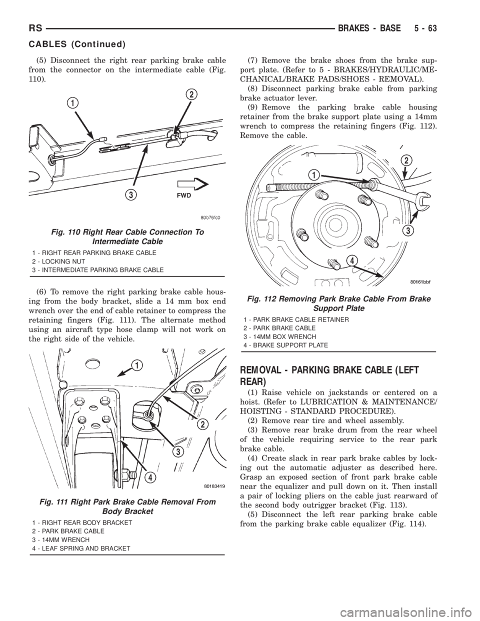
(5) Disconnect the right rear parking brake cable
from the connector on the intermediate cable (Fig.
110).
(6) To remove the right parking brake cable hous-
ing from the body bracket, slide a 14 mm box end
wrench over the end of cable retainer to compress the
retaining fingers (Fig. 111). The alternate method
using an aircraft type hose clamp will not work on
the right side of the vehicle.(7) Remove the brake shoes from the brake sup-
port plate. (Refer to 5 - BRAKES/HYDRAULIC/ME-
CHANICAL/BRAKE PADS/SHOES - REMOVAL).
(8) Disconnect parking brake cable from parking
brake actuator lever.
(9) Remove the parking brake cable housing
retainer from the brake support plate using a 14mm
wrench to compress the retaining fingers (Fig. 112).
Remove the cable.
REMOVAL - PARKING BRAKE CABLE (LEFT
REAR)
(1) Raise vehicle on jackstands or centered on a
hoist. (Refer to LUBRICATION & MAINTENANCE/
HOISTING - STANDARD PROCEDURE).
(2) Remove rear tire and wheel assembly.
(3) Remove rear brake drum from the rear wheel
of the vehicle requiring service to the rear park
brake cable.
(4) Create slack in rear park brake cables by lock-
ing out the automatic adjuster as described here.
Grasp an exposed section of front park brake cable
near the equalizer and pull down on it. Then install
a pair of locking pliers on the cable just rearward of
the second body outrigger bracket (Fig. 113).
(5) Disconnect the left rear parking brake cable
from the parking brake cable equalizer (Fig. 114).
Fig. 110 Right Rear Cable Connection To
Intermediate Cable
1 - RIGHT REAR PARKING BRAKE CABLE
2 - LOCKING NUT
3 - INTERMEDIATE PARKING BRAKE CABLE
Fig. 111 Right Park Brake Cable Removal From
Body Bracket
1 - RIGHT REAR BODY BRACKET
2 - PARK BRAKE CABLE
3 - 14MM WRENCH
4 - LEAF SPRING AND BRACKET
Fig. 112 Removing Park Brake Cable From Brake
Support Plate
1 - PARK BRAKE CABLE RETAINER
2 - PARK BRAKE CABLE
3 - 14MM BOX WRENCH
4 - BRAKE SUPPORT PLATE
RSBRAKES - BASE5-63
CABLES (Continued)
Page 1690 of 4284
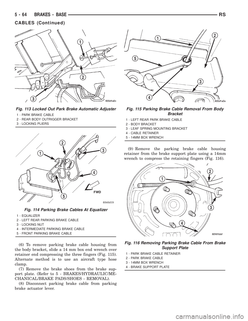
(6) To remove parking brake cable housing from
the body bracket, slide a 14 mm box end wrench over
retainer end compressing the three fingers (Fig. 115).
Alternate method is to use an aircraft type hose
clamp.
(7) Remove the brake shoes from the brake sup-
port plate. (Refer to 5 - BRAKES/HYDRAULIC/ME-
CHANICAL/BRAKE PADS/SHOES - REMOVAL).
(8) Disconnect parking brake cable from parking
brake actuator lever.(9) Remove the parking brake cable housing
retainer from the brake support plate using a 14mm
wrench to compress the retaining fingers (Fig. 116).
Fig. 113 Locked Out Park Brake Automatic Adjuster
1 - PARK BRAKE CABLE
2 - REAR BODY OUTRIGGER BRACKET
3 - LOCKING PLIERS
Fig. 114 Parking Brake Cables At Equalizer
1 - EQUALIZER
2 - LEFT REAR PARKING BRAKE CABLE
3 - LOCKING NUT
4 - INTERMEDIATE PARKING BRAKE CABLE
5 - FRONT PARKING BRAKE CABLE
Fig. 115 Parking Brake Cable Removal From Body
Bracket
1 - LEFT REAR PARK BRAKE CABLE
2 - BODY BRACKET
3 - LEAF SPRING MOUNTING BRACKET
4 - CABLE RETAINER
5 - 14MM BOX WRENCH
Fig. 116 Removing Parking Brake Cable From Brake
Support Plate
1 - PARK BRAKE CABLE RETAINER
2 - PARK BRAKE CABLE
3 - 14MM BOX WRENCH
4 - BRAKE SUPPORT PLATE
5 - 64 BRAKES - BASERS
CABLES (Continued)
Page 1691 of 4284
INSTALLATION - PARKING BRAKE CABLE
(FRONT)
(1) Pass front parking brake cable assembly
through hole in floor pan from the inside of the vehi-
cle.
(2) Pass cable strand button through the hole in
the lever (pedal) assembly bracket.
(3) Install cable retainer onto the park brake cable
and then install cable retainer into pedal assembly
bracket.
(4) Install the end of the park brake cable into the
retainer previously installed into the park brake
pedal bracket.
(5) Install cable strand button into the clevis on
the park brake pedal mechanism.
(6) Install the front park brake cable floor pan seal
into hole in floor pan . Seal is to be installed so the
flange on the seal is flush with the floor pan (Fig.
106). Fold carpeting back down on floor.
(7) Raise vehicle.
(8) Insert brake cable and housing into body out-
rigger bracket making certain that housing retainer
fingers lock the housing firmly into place (Fig. 105).
(9) Manually reset the automatic self-adjusting
mechanism tension of the parking brake lever (pedal)
assembly. (Refer to 5 - BRAKES - STANDARD PRO-
CEDURE).
(10) Assemble the park brake cables onto the park
brake cable equalizer (Fig. 104).
(11) Lower vehicle and apply the park brake pedal
1 time. This will seat the parking brake cables.
INSTALLATION - PARKING BRAKE CABLE
(INTERMEDIATE)
(1) Install the ends of the park brake cables
through the frame rails and into the side brackets.
(2) Install the locking nuts at each end of the cable
and securely tighten (Fig. 107) (Fig. 108).
(3) If the vehicle is a short-wheel-base model, it
will be necessary to reinstall the fuel tank to its nor-
mal mounting position. (Refer to 14 - FUEL SYS-
TEM/FUEL DELIVERY/FUEL TANK -
INSTALLATION).(4) Install the intermediate parking brake cable on
the cable connector at the right rear parking brake
cable (Fig. 108).
(5) Install the intermediate park brake cable on
the cable equalizer (Fig. 107).
(6) Remove the locking pliers from the front park
brake cable. This will activate the automatic adjuster
and correctly adjust the parking brake cables.
(7) Install and position the foam collar on the
parking brake cable to prevent it from rattling
against the vehicle's floor.
(8) Lower the vehicle and apply the park brake
pedal 1 time, this will seat the park brake cables.
INSTALLATION - PARKING BRAKE CABLE
(RIGHT REAR)
(1) Install the rear parking brake cable in the
brake support plate. Insert cable housing retainer
into brake support plate making certain that cable
housing retainer fingers lock the housing and
retainer firmly into place.
(2) Attach the parking brake cable onto the park-
ing brake actuator lever.
(3) Install the brake shoes on the rear brake sup-
port plate. (Refer to 5 - BRAKES/HYDRAULIC/ME-
CHANICAL/BRAKE PADS/SHOES -
INSTALLATION).
(4) Insert cable housing retainer into body outrig-
ger bracket making certain that cable housing
retainer fingers lock the housing firmly into place.
(5) Connect the right rear parking brake cable to
the connector on the intermediate parking brake
cable (Fig. 110).
(6) Install the brake drum, then the wheel and tire
assembly.
(7) Remove the locking pliers from the front park
brake cable. This will automatically adjust the park
brake cables.
(8) Lower the vehicle.
(9) Apply and release park brake pedal 1 time.
This will seat the park brake cables.
RSBRAKES - BASE5-65
CABLES (Continued)
Page 1692 of 4284
INSTALLATION - PARKING BRAKE CABLE
(LEFT REAR)
(1) Install the rear parking brake cable in the
brake support plate. Insert cable housing retainer
into brake support plate making certain that cable
housing retainer fingers lock the housing and
retainer firmly into place.
(2) Attach the parking brake cable onto the park
brake actuator lever.
(3) Install the brake shoes on the rear brake sup-
port plate. (Refer to 5 - BRAKES/HYDRAULIC/ME-
CHANICAL/BRAKE PADS/SHOES -
INSTALLATION).
(4) Insert cable housing retainer into body outrig-
ger bracket making certain that cable housing
retainer fingers lock the housing firmly into place.
(5) Connect rear parking brake cable to the equal-
izer bracket (Fig. 114).
(6) Install brake drum, and wheel and tire assem-
bly.
(7) Remove the locking pliers from the front park
brake cable. This will automatically adjust the park
brake cables.
(8) Apply and release park brake pedal 1 time.
This will seat the park brake cables.
ADJUSTMENT - CABLES
The park brake cables on this vehicle have an
automatic self adjuster built into the park brake
pedal mechanism. When the foot operated park brake
pedal is in its released (upward most) position, a
clock spring automatically adjusts the park brake
cables. The park brake cables are adjusted (ten-
sioned) just enough to remove all the slack from the
cables. The automatic adjuster system will not over
adjust the cables causing rear brake drag.
Due to the automatic adjust feature of the park
brake pedal, adjustment of the parking brake cables
on these vehicles relies on proper drum brake and
park brake shoe adjustment. (Refer to 5 - BRAKES/
HYDRAULIC/MECHANICAL/DRUM - ADJUST-
MENTS) and (Refer to 5 - BRAKES/PARKING
BRAKE/SHOES - ADJUSTMENTS).
When the park brake pedal is applied the self
adjuster is by-passed and the pedal operates nor-
mally to engage the park brakes.
When a service procedure needs to be performed on
the park brake pedal or the park brake cables, the
automatic self adjuster can be manually locked out
by the service technician.
5 - 66 BRAKES - BASERS
CABLES (Continued)