2001 CHRYSLER VOYAGER transmission
[x] Cancel search: transmissionPage 53 of 4284

seconds instead of 5, the CMTC will set the
variance to 8 and enter the fast calibration
mode.
3. The VAR light will come on and the last variance
setting will be displayed.
4. Press the STEP button to set the zone number.
5. Press the US/M button and resume normal op-
eration.
NOTE: Do not attach any magnetic device
such as a magnetic CB antenna to the
vehicle. This can cause the compass to give
false readings.
3.15 POWER DOOR LOCK SYSTEM
When the BCM receives input for a lock request
from a door lock switch, RKE or cylinder lock switch
(only with VTSS), it will turn the lock driver on for
a specified time of 375 msec. If the request is there
beyond 375 msec, the BCM considers the door lock
signal stuck. Once a door lock or unlock signal is
stuck for longer than 10 seconds, the BCM will set
a trouble code and the signal input is ignored until
the stuck condition disappears. The door lock
switches provide a variable amount of resistance
thereby dropping the voltage of the multiplexed
(MUX) circuit and the BCM will respond to that
command.
3.15.1 SLIDING DOOR MEMORY LOCK
When the BCM receives an input for a lock
request and a sliding door is open, the BCM will
turn on the lock driver as described above, and will
turn it on again when all sliding doors are closed.
NOTE: If the BCM receives an unlock input before
a sliding door is closed, this will cancel the memory
lock.
3.15.2 DOOR LOCK INHIBIT
When the key is in the ignition and in any
position and either front door is open, the door lock
switches LOCK functions are disabled. The UN-
LOCK functions are still functional. This protects
against locking the vehicle with the keys still in the
ignition. The RKE key fob will still lock the doors as
usual. This allows the driver to lock the vehicle with
the engine running for warm up.
3.15.3 AUTOMATIC DOOR LOCKS
This feature can be enabled or disabled by using
either the DRBIIItor the customer programming
method. When enabled all the doors will lock when
the vehicle reaches a speed of 18 MPH (29 KMH)
and all the doors are closed. If a door is opened and
the vehicle slows to below 18 MPH (29 KMH), thedoor locks will operate again once all doors are
closed and the speed is above 15 MPH (24 KMH).
3.15.4 REMOTE KEYLESS ENTRY (RKE)
The body control module interfaces with the RKE
module via a one-way serial bus interface. The RKE
module is not on the PCI bus. The RKE module
sends a 0-5 volt pulse width signal to the BCM
depending on which button on the transmitter was
pressed. The BCM controls the door lock/unlock
functions and the arming/disarming of the Vehicle
Theft Security System (if equipped) and the activa-
tion of illuminated entry. The BCM will also send
the appropriate messages to the Power Sliding
Doors and Power Liftgate modules. The Intelligent
Power Module (IPM) activates the park lamps,
headlamps, and horn for horn chirp when sent the
appropriate message from the BCM as received
from the RKE transmitter. When a one-button
press is made for unlock, both driver side doors will
unlock and the front and rear turn signal will flash.
When a second press is initiated (within 5 seconds
of the first) both passenger doors will unlock and all
four turn signals will flash.
The RKE module is capable of retaining up to 4
individual access codes (4 transmitters). If the
PRNDL is in any position except park, the BCM will
ground the interface thereby disabling the RKE.
The 2 button transmitter will have 2-CR2016
batteries in series. The 5 button transmitter will
have 1-CR2016 battery. The minimum battery life
should be approximately 4.7 years based on 20
transmissions a day at 84ÉF (25ÉC). Using the
DRBIIItand selecting RKE FOB Test can test the
transmitter.
The RKE module can be programmed via the
DRBIIItor the customer programming method.
The BCM will only allow programming mode to be
entered when the ignition is in the on position, the
PRNDL is in park position, and the VTSS (if
equipped) is in the disarmed mode.
3.16 POWER FOLDING MIRRORS
The power folding mirrors are powered to two
positions: folded and unfolded. The driver may
choose fold or unfold with a switch that is located on
the right side of the steering column. The folding
mirror switch grounds a sense wire that comes from
the Body Control Module when it is placed in the
fold position. The mirrors will move to the position
designated by the switch whether the ignition
switch is the On or Off position and both front doors
are closed. When the Power Folding Mirror switch
is left in the fold position during a vehicle exit the
mirrors will automatically unfold then refold after
both front doors are closed. This is to prevent mirror
contact with either front door when opened. When
24
GENERAL INFORMATION
Page 59 of 4284
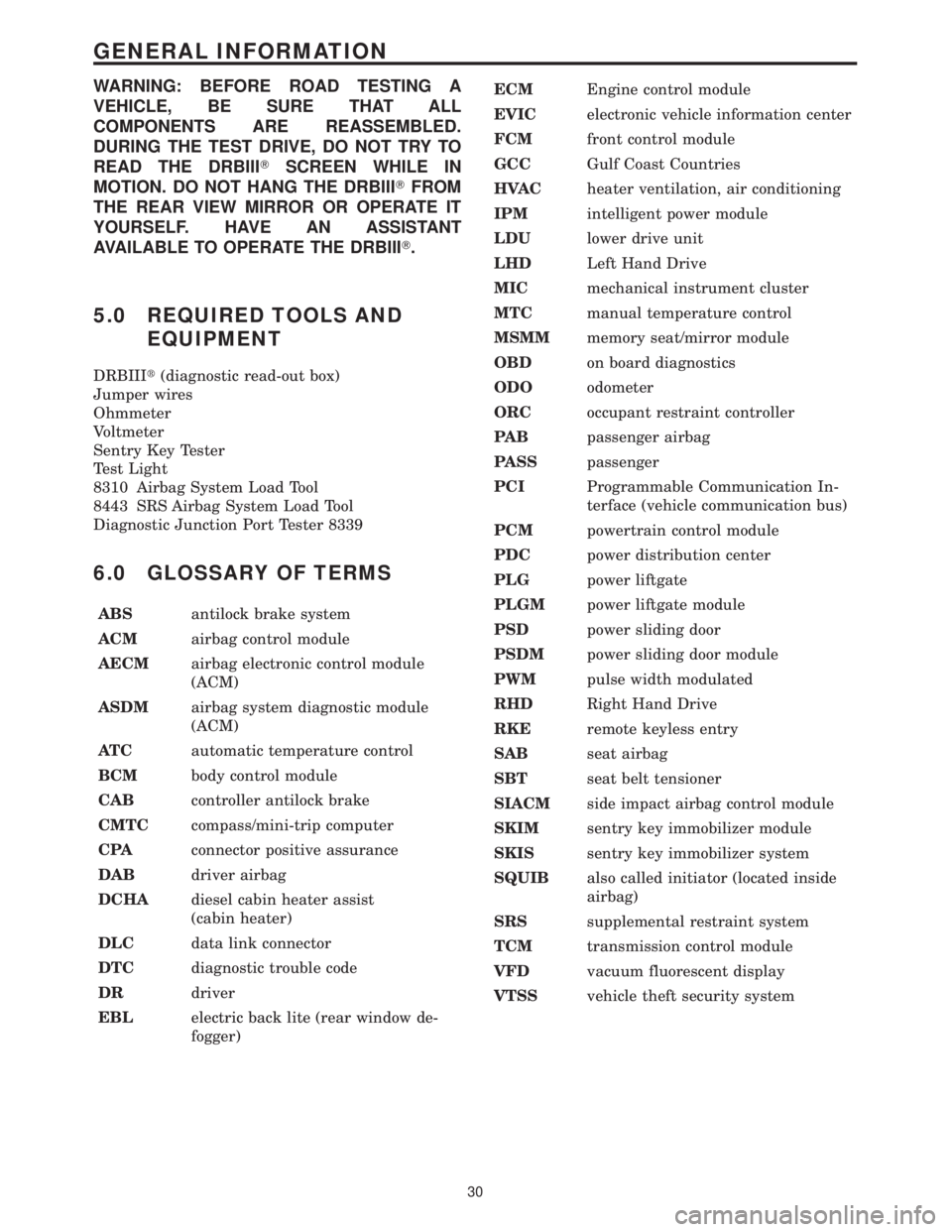
WARNING: BEFORE ROAD TESTING A
VEHICLE, BE SURE THAT ALL
COMPONENTS ARE REASSEMBLED.
DURING THE TEST DRIVE, DO NOT TRY TO
READ THE DRBIIITSCREEN WHILE IN
MOTION. DO NOT HANG THE DRBIIITFROM
THE REAR VIEW MIRROR OR OPERATE IT
YOURSELF. HAVE AN ASSISTANT
AVAILABLE TO OPERATE THE DRBIIIT.
5.0 REQUIRED TOOLS AND
EQUIPMENT
DRBIIIt(diagnostic read-out box)
Jumper wires
Ohmmeter
Voltmeter
Sentry Key Tester
Test Light
8310 Airbag System Load Tool
8443 SRS Airbag System Load Tool
Diagnostic Junction Port Tester 8339
6.0 GLOSSARY OF TERMS
ABSantilock brake system
ACMairbag control module
AECMairbag electronic control module
(ACM)
ASDMairbag system diagnostic module
(ACM)
AT Cautomatic temperature control
BCMbody control module
CABcontroller antilock brake
CMTCcompass/mini-trip computer
CPAconnector positive assurance
DABdriver airbag
DCHAdiesel cabin heater assist
(cabin heater)
DLCdata link connector
DTCdiagnostic trouble code
DRdriver
EBLelectric back lite (rear window de-
fogger)ECMEngine control module
EVICelectronic vehicle information center
FCMfront control module
GCCGulf Coast Countries
HVACheater ventilation, air conditioning
IPMintelligent power module
LDUlower drive unit
LHDLeft Hand Drive
MICmechanical instrument cluster
MTCmanual temperature control
MSMMmemory seat/mirror module
OBDon board diagnostics
ODOodometer
ORCoccupant restraint controller
PA Bpassenger airbag
PASSpassenger
PCIProgrammable Communication In-
terface (vehicle communication bus)
PCMpowertrain control module
PDCpower distribution center
PLGpower liftgate
PLGMpower liftgate module
PSDpower sliding door
PSDMpower sliding door module
PWMpulse width modulated
RHDRight Hand Drive
RKEremote keyless entry
SABseat airbag
SBTseat belt tensioner
SIACMside impact airbag control module
SKIMsentry key immobilizer module
SKISsentry key immobilizer system
SQUIBalso called initiator (located inside
airbag)
SRSsupplemental restraint system
TCMtransmission control module
VFDvacuum fluorescent display
VTSSvehicle theft security system
30
GENERAL INFORMATION
Page 81 of 4284

Symptom List:
LEFT SIACM ACCELEROMETER 1 - ACTIVE
LEFT SIACM ACCELEROMETER 1 - STORED
LEFT SIACM ACCELEROMETER 2 - ACTIVE
LEFT SIACM ACCELEROMETER 2 - STORED
LEFT SIACM INTERNAL 1 - ACTIVE
LEFT SIACM INTERNAL 1 - STORED
LEFT SIACM OUTPUT DRIVER 1 - ACTIVE
LEFT SIACM OUTPUT DRIVER 1 - STORED
LEFT SIACM, LOSS OF IGNITION RUN-START - ACTIVE
LEFT SIACM, NO PCI TRANSMISSION - ACTIVE
Test Note: All symptoms listed above are diagnosed using the same tests.
The title for the tests will be LEFT SIACM ACCELEROMETER
1 - ACTIVE.
When Monitored and Set Condition:
LEFT SIACM ACCELEROMETER 1 - ACTIVE
When Monitored: When the ignition on, the Left SIACM on board diagnostics continu-
ously performs internal circuit tests.
Set Condition: This DTC will set if the Left SIACM identifies an out of range internal
circuit
LEFT SIACM ACCELEROMETER 1 - STORED
When Monitored: When the ignition on, the Left SIACM on board diagnostics continu-
ously performs internal circuit tests.
Set Condition: This DTC will set if the Left SIACM identifies an out of range internal
circuit.
LEFT SIACM ACCELEROMETER 2 - ACTIVE
When Monitored: When the ignition on, the Left SIACM on board diagnostics continu-
ously performs internal circuit tests.
Set Condition: This DTC will set if the Left SIACM identifies an out of range internal
circuit.
LEFT SIACM ACCELEROMETER 2 - STORED
When Monitored: When the ignition on, the Left SIACM on board diagnostics continu-
ously performs internal circuit tests.
Set Condition: This DTC will set if the Left SIACM identifies an out of range internal
circuit.
52
AIRBAG
Page 82 of 4284

LEFT SIACM INTERNAL 1 - ACTIVE
When Monitored: When the ignition on, the Left SIACM on board diagnostics continu-
ously performs internal circuit tests.
Set Condition: This DTC will set if the Left SIACM identifies an out of range internal
circuit.
LEFT SIACM INTERNAL 1 - STORED
When Monitored: When the ignition on, the Left SIACM on board diagnostics continu-
ously performs internal circuit tests.
Set Condition: This DTC will set if the Left SIACM identifies an out of range internal
circuit.
LEFT SIACM OUTPUT DRIVER 1 - ACTIVE
When Monitored: When the ignition on, the Left SIACM on board diagnostics continu-
ously performs internal circuit tests.
Set Condition: This DTC will set if the Left SIACM identifies an out of range internal
circuit.
LEFT SIACM OUTPUT DRIVER 1 - STORED
When Monitored: When the ignition on, the Left SIACM on board diagnostics continu-
ously performs internal circuit tests.
Set Condition: This DTC will set if the Left SIACM identifies an out of range internal
circuit.
LEFT SIACM, LOSS OF IGNITION RUN-START - ACTIVE
When Monitored: With the ignition in the run or start position the Left SIACM monitors
the SIACM Run-Start Driver circuit for proper system voltage. This is an active trouble
code only.
Set Condition: If the voltage on the SIACM Run-Start Driver circuit is below 4.0 volts,
the code will set.
LEFT SIACM, NO PCI TRANSMISSION - ACTIVE
When Monitored: With the ignition in the On position and the Left SIACM transmitting
information on the PCI BUS.
Set Condition: The code will set, if the Left SIACM cannot detect the Left SIACM
transmitting information on the PCI BUS for 4 consecutive seconds. NOTE: Any PCI Bus
Failure will cause this code to set.
53
AIRBAG
LEFT SIACM ACCELEROMETER 1 - ACTIVE ÐContinued
Page 84 of 4284

Symptom List:
LEFT SIACM, NO PCI TRANSMISSION - STORED
LEFT SIACM, NO PCM MESSAGE - STORED
LEFT SIACM, SEAT SQUIB CIRCUIT OPEN - STORED
LEFT SIACM, SEAT SQUIB CIRCUIT SHORT - STORED
LEFT SIACM, SEAT SQUIB SHORT TO BATTERY - STORED
LEFT SIACM, SEAT SQUIB SHORT TO GROUND - STORED
ORC, INTERROGATE LEFT SIACM - STORED
ORC, NO LEFT SIACM MESSAGE - STORED
Test Note: All symptoms listed above are diagnosed using the same tests.
The title for the tests will be LEFT SIACM, NO PCI TRANS-
MISSION - STORED.
When Monitored and Set Condition:
LEFT SIACM, NO PCI TRANSMISSION - STORED
When Monitored: With the ignition in the On position and the Left SIACM transmitting
information on the PCI BUS.
Set Condition: The code will set if, the Left SIACM cannot detect the Left SIACM
transmitting information on the PCI BUS for 4 consecutive seconds. NOTE: Any PCI Bus
Failure will cause this code to set.
LEFT SIACM, SEAT SQUIB CIRCUIT OPEN - STORED
When Monitored: When the ignition is ON, the Left SIACM monitors the Left Seat Squib
circuits for high resistance.
Set Condition: The Left SIACM has detected an open circuit or high resistance on the
Left Seat Squib circuits.
LEFT SIACM, SEAT SQUIB CIRCUIT SHORT - STORED
When Monitored: When the ignition is on, the Left SIACM monitors the resistance of the
Left Seat Squib circuits.
Set Condition: The Left SIACM has detected low resistance in the Left Seat Squib
circuits.
LEFT SIACM, SEAT SQUIB SHORT TO BATTERY - STORED
When Monitored: When the ignition is on, the Left SIACM monitors the voltage of the
Left Seat Squib circuits.
Set Condition: The Left SIACM has detected high voltage on the Left Seat Squib circuits.
55
AIRBAG
Page 85 of 4284

LEFT SIACM, SEAT SQUIB SHORT TO GROUND - STORED
When Monitored: When the ignition is on, the Left SIACM monitors the resistance of the
left Seat Squib circuits for low resistance.
Set Condition: The Left SIACM has detected a short to ground in the left Seat Squib
circuits.
ORC, INTERROGATE LEFT SIACM - STORED
When Monitored: With ignition on, the ORC monitors the PCI Bus for a Left SIACM
status message containing the airbag warning lamp9On or OFF9request. The status
message is sent to the ORC once each second or upon any change in the active DTCs.
Set Condition: The Code will set, if the ORC receives an9Lamp On9status message from
the Left SIACM. NOTE: This indicates that there was an active diagnostic trouble code in
the Left SIACM.
ORC, NO LEFT SIACM MESSAGE - STORED
When Monitored: With ignition on, the ORC monitors the PCI Bus for the Left SIACM
status message. The Left SIACM transmits the status message to the ORC at 1 - second
intervals.
Set Condition: If the ORC fails to see the Left SIACM status message on the PCI Bus for
10 seconds the code will set.
56
AIRBAG
LEFT SIACM, NO PCI TRANSMISSION - STORED ÐContinued
Page 86 of 4284

POSSIBLE CAUSES
CHECKING FOR ACTIVE LEFT SIACM DTCS
STORED CODE PRESENT
TEST ACTION APPLICABILITY
1 Turn ignition on.
NOTE: Ensure the battery is fully charged.
Active codes must be resolved before diagnosing stored codes.
With the DRBIIIt, record and erase all DTCs from all modules.
With the DRB III monitor active codes as you work through the system.
Wiggle the wiring harness and connectors of the Airbag System.
NOTE: Check connectors - Clean and repair as necessary.
The following additional checks may assist you in identifying a possible intermittent
problem:
- Visually inspect related wire harness connectors. Look for broken, bent, pushed out,
spread, corroded, or contaminated terminals.
- Visually inspect related harnesses. Look for chafed, pierced, pinched or partially
broken wire.
- Refer to Wiring Diagrams and Technical Service Bulletins that may apply.
Did the DTC become active ?All
Ye s®Select appropriate symptom from Symptom List and continue
with diagnosis.
No®No problem found at this time. NOTE: interrogate the ORC and
Right SIACM for DTCs. Erase all codes in all airbag modules
before returning vehicle to customer.
57
AIRBAG
LEFT SIACM, NO PCI TRANSMISSION - STORED ÐContinued
Page 99 of 4284

Symptom List:
ORC ACCELEROMETER - ACTIVE
ORC ACCELEROMETER - STORED
ORC INTERNAL 1 - ACTIVE
ORC INTERNAL 1 - STORED
ORC INTERNAL 2 - ACTIVE
ORC INTERNAL 2 - STORED
ORC OUTPUT DRIVER 1 - ACTIVE
ORC OUTPUT DRIVER 1 - STORED
ORC OUTPUT DRIVER 2 - ACTIVE
ORC OUTPUT DRIVER 2 - STORED
ORC STORED ENERGY FIRING - ACTIVE
ORC STORED ENERGY FIRING - STORED
ORC, NO PCI TRANSMISSION - ACTIVE
Test Note: All symptoms listed above are diagnosed using the same tests.
The title for the tests will be ORC ACCELEROMETER -
ACTIVE.
When Monitored and Set Condition:
ORC ACCELEROMETER - ACTIVE
When Monitored: When the ignition is on, the ORC on board diagnostics continuously
performs internal circuit tests.
Set Condition: This DTC will set if the ORC identifies an out of range internal circuit.
ORC ACCELEROMETER - STORED
When Monitored: When the ignition on, the ORC on board diagnostics continuously
performs internal circuit tests.
Set Condition: This DTC will set if the ORC identifies an out of range internal circuit.
ORC INTERNAL 1 - ACTIVE
When Monitored: When the ignition on, the ORC on board diagnostics continuously
performs internal circuit tests.
Set Condition: This DTC will set if the ORC identifies an out of range internal circuit.
ORC INTERNAL 1 - STORED
When Monitored: When the ignition on, the ORC on board diagnostics continuously
performs internal circuit tests.
Set Condition: This DTC will set if the ORC identifies an out of range internal circuit.
70
AIRBAG