2001 CHRYSLER VOYAGER fuel filter location
[x] Cancel search: fuel filter locationPage 2756 of 4284
OIL
STANDARD PROCEDURE - ENGINE OIL AND
FILTER CHANGE
Change engine oil at mileage and time intervals
described in the Maintenance Schedule. (Refer to
LUBRICATION & MAINTENANCE/MAINTE-
NANCE SCHEDULES - DESCRIPTION)
WARNING: NEW OR USED ENGINE OIL CAN BE
IRRITATING TO THE SKIN. AVOID PROLONGED OR
REPEATED SKIN CONTACT WITH ENGINE OIL.
CONTAMINANTS IN USED ENGINE OIL, CAUSED BY
INTERNAL COMBUSTION, CAN BE HAZARDOUS TO
YOUR HEALTH. THOROUGHLY WASH EXPOSED
SKIN WITH SOAP AND WATER. DO NOT WASH
SKIN WITH GASOLINE, DIESEL FUEL, THINNER, OR
SOLVENTS, HEALTH PROBLEMS CAN RESULT. DO
NOT POLLUTE, DISPOSE OF USED ENGINE OIL
PROPERLY. CONTACT YOUR DEALER OR GOVERN-
MENT AGENCY FOR LOCATION OF COLLECTION
CENTER IN YOUR AREA.
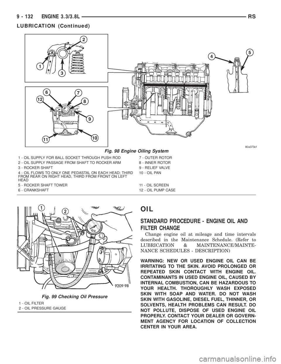
Fig. 98 Engine Oiling System
1 - OIL SUPPLY FOR BALL SOCKET THROUGH PUSH ROD 7 - OUTER ROTOR
2 - OIL SUPPLY PASSAGE FROM SHAFT TO ROCKER ARM 8 - INNER ROTOR
3 - ROCKER SHAFT 9 - RELIEF VALVE
4 - OIL FLOWS TO ONLY ONE PEDASTAL ON EACH HEAD; THIRD
FROM REAR ON RIGHT HEAD, THIRD FROM FRONT ON LEFT
HEAD10 - OIL PAN
5 - ROCKER SHAFT TOWER 11 - OIL SCREEN
6 - CRANKSHAFT 12 - OIL PUMP CASE
Fig. 99 Checking Oil Pressure
1 - OIL FILTER
2 - OIL PRESSURE GAUGE
9 - 132 ENGINE 3.3/3.8LRS
LUBRICATION (Continued)
Page 2874 of 4284
The fuel filter is replaceable, it is mounted on the
outside and on top of the fuel tank. Refer to the
Maintenance Schedules in the Introduction section of
this manual for recommended fuel filter replacement
intervals.
FFV REPLACEMENT PARTS
Many components in a Flexible Fuel Vehicle (FFV)
are designed to be compatible with ethanol. Always
be sure that the vehicle is serviced with correct etha-
nol compatible parts.
CAUTION: Replacing fuel system components with
non-ethanol compatible components can damage
your vehicle and may void the warranty.
OPERATION
The fuel system is provided fuel pressure by an in-
tank pump module. The PCM controls the operation
of the fuel system by providing battery voltage to the
fuel pump through the fuel pump relay. The PCM
requires only three inputs and a good ground to oper-
ate the fuel pump relay. The three inputs are:
²Ignition voltage
²Crankshaft Position (CKP) sensor
²Camshaft Position (CMP) sensor
DIAGNOSIS AND TESTING - FUEL DELIVERY
SYSTEM
(Refer to Appropriate Diagnositic Information)
STANDARD PROCEDURE - FUEL SYSTEM
PRESSURE RELEASE PROCEDURE
(1) Remove Fuel Pump relay from Power Distribu-
tion Center (PDC). For location of relay, refer to label
on underside of PDC cover.(2) Start and run engine until it stalls.
(3) Attempt restarting engine until it will no
longer run.
(4) Turn ignition key to OFF position.
(5) Place a rag or towel below fuel line quick-con-
nect fitting at fuel rail.
(6) Return fuel pump relay to PDC.
(7) One or more Diagnostic Trouble Codes (DTC's)
may have been stored in PCM memory due to fuel
pump relay removal. The DRB IIItscan tool must be
used to erase a DTC.
STANDARD PROCEDURE - DRAINING FUEL
TANK
(1) Release fuel system pressure, refer to the Fuel
System Release Procedure in this section.
(2) Insert a 1/4 inch siphon (max. O. D. 5/16) hose
from a portable fuel siphoning tank through the fuel
filler neck opening into the fuel tank. Hose most
have a 30 degree angle cut on the end to bypass the
check valve in the end of the filler neck. Refer to the
siphoning tank's Manufacturing Instructions.
(3) Drain fuel from fuel tank into siphoning tank.
SPECIFICATIONS
FUEL SYSTEM PRESSURE
400 kpa634 kpa (58 psi65 psi)
TORQUE
DESCRIPTION N´m Ft. Lbs. In. Lbs.
Fuel Rail 2.4L 22 200
Fuel Rail 3.3/3.8L 11.8 105
Fuel Tank Strap 54 40
Fuel Tank T Strap 28.2 250
Fuel Filter Bolt 4.5 40
14 - 2 FUEL DELIVERYRS
FUEL DELIVERY (Continued)
Page 2911 of 4284
FUEL DELIVERY
TABLE OF CONTENTS
page page
FUEL RAIL
DESCRIPTION............................3
OPERATION.............................3
REMOVAL...............................3
INSTALLATION............................4
FUEL FILTER / WATER SEPARATOR
DESCRIPTION............................4
OPERATION.............................4
FUEL LINES
DESCRIPTION............................5
OPERATION.............................5
DIAGNOSIS AND TESTING..................5HIGH-PRESSURE FUEL LINE LEAKS........5
FUEL TRANSFER PUMP
DESCRIPTION............................6
OPERATION.............................6
FUEL INJECTION PUMP
DESCRIPTION............................6
REMOVAL...............................6
INSTALLATION............................8
WATER IN FUEL SENSOR
DESCRIPTION............................9
OPERATION.............................9
FUEL RAIL
DESCRIPTION
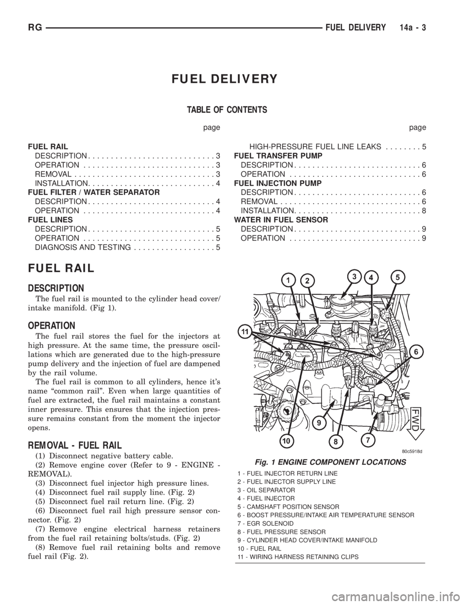
The fuel rail is mounted to the cylinder head cover/
intake manifold. (Fig 1).
OPERATION
The fuel rail stores the fuel for the injectors at
high pressure. At the same time, the pressure oscil-
lations which are generated due to the high-pressure
pump delivery and the injection of fuel are dampened
by the rail volume.
The fuel rail is common to all cylinders, hence it's
name ªcommon railº. Even when large quantities of
fuel are extracted, the fuel rail maintains a constant
inner pressure. This ensures that the injection pres-
sure remains constant from the moment the injector
opens.
REMOVAL - FUEL RAIL
(1) Disconnect negative battery cable.
(2) Remove engine cover (Refer to 9 - ENGINE -
REMOVAL).
(3) Disconnect fuel injector high pressure lines.
(4) Disconnect fuel rail supply line. (Fig. 2)
(5) Disconnect fuel rail return line. (Fig. 2)
(6) Disconnect fuel rail high pressure sensor con-
nector. (Fig. 2)
(7) Remove engine electrical harness retainers
from the fuel rail retaining bolts/studs. (Fig. 2)
(8) Remove fuel rail retaining bolts and remove
fuel rail (Fig. 2).Fig. 1 ENGINE COMPONENT LOCATIONS
1 - FUEL INJECTOR RETURN LINE
2 - FUEL INJECTOR SUPPLY LINE
3 - OIL SEPARATOR
4 - FUEL INJECTOR
5 - CAMSHAFT POSITION SENSOR
6 - BOOST PRESSURE/INTAKE AIR TEMPERATURE SENSOR
7 - EGR SOLENOID
8 - FUEL PRESSURE SENSOR
9 - CYLINDER HEAD COVER/INTAKE MANIFOLD
10 - FUEL RAIL
11 - WIRING HARNESS RETAINING CLIPS
RGFUEL DELIVERY14a-3
Page 2914 of 4284
FUEL TRANSFER PUMP
DESCRIPTION
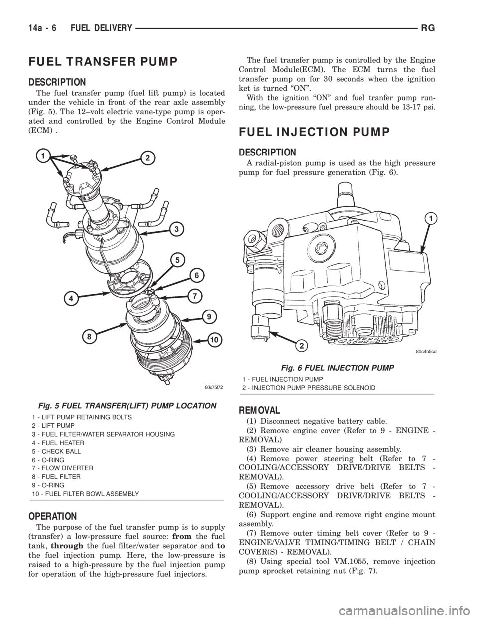
The fuel transfer pump (fuel lift pump) is located
under the vehicle in front of the rear axle assembly
(Fig. 5). The 12±volt electric vane-type pump is oper-
ated and controlled by the Engine Control Module
(ECM) .
OPERATION
The purpose of the fuel transfer pump is to supply
(transfer) a low-pressure fuel source:fromthe fuel
tank,throughthe fuel filter/water separator andto
the fuel injection pump. Here, the low-pressure is
raised to a high-pressure by the fuel injection pump
for operation of the high-pressure fuel injectors.The fuel transfer pump is controlled by the Engine
Control Module(ECM). The ECM turns the fuel
transfer pump on for 30 seconds when the ignition
ket is turned ªONº.
With the ignition ªONº and fuel tranfer pump run-
ning, the low-pressure fuel pressure should be 13-17 psi.
FUEL INJECTION PUMP
DESCRIPTION
A radial-piston pump is used as the high pressure
pump for fuel pressure generation (Fig. 6).
REMOVAL
(1) Disconnect negative battery cable.
(2) Remove engine cover (Refer to 9 - ENGINE -
REMOVAL)
(3) Remove air cleaner housing assembly.
(4) Remove power steering belt (Refer to 7 -
COOLING/ACCESSORY DRIVE/DRIVE BELTS -
REMOVAL).
(5) Remove accessory drive belt (Refer to 7 -
COOLING/ACCESSORY DRIVE/DRIVE BELTS -
REMOVAL).
(6) Support engine and remove right engine mount
assembly.
(7) Remove outer timing belt cover (Refer to 9 -
ENGINE/VALVE TIMING/TIMING BELT / CHAIN
COVER(S) - REMOVAL).
(8) Using special tool VM.1055, remove injection
pump sprocket retaining nut (Fig. 7).
Fig. 5 FUEL TRANSFER(LIFT) PUMP LOCATION
1 - LIFT PUMP RETAINING BOLTS
2 - LIFT PUMP
3 - FUEL FILTER/WATER SEPARATOR HOUSING
4 - FUEL HEATER
5 - CHECK BALL
6 - O-RING
7 - FLOW DIVERTER
8 - FUEL FILTER
9 - O-RING
10 - FUEL FILTER BOWL ASSEMBLY
Fig. 6 FUEL INJECTION PUMP
1 - FUEL INJECTION PUMP
2 - INJECTION PUMP PRESSURE SOLENOID
14a - 6 FUEL DELIVERYRG
Page 2922 of 4284
(3) Disconnect intake air temperature electrical
connector.
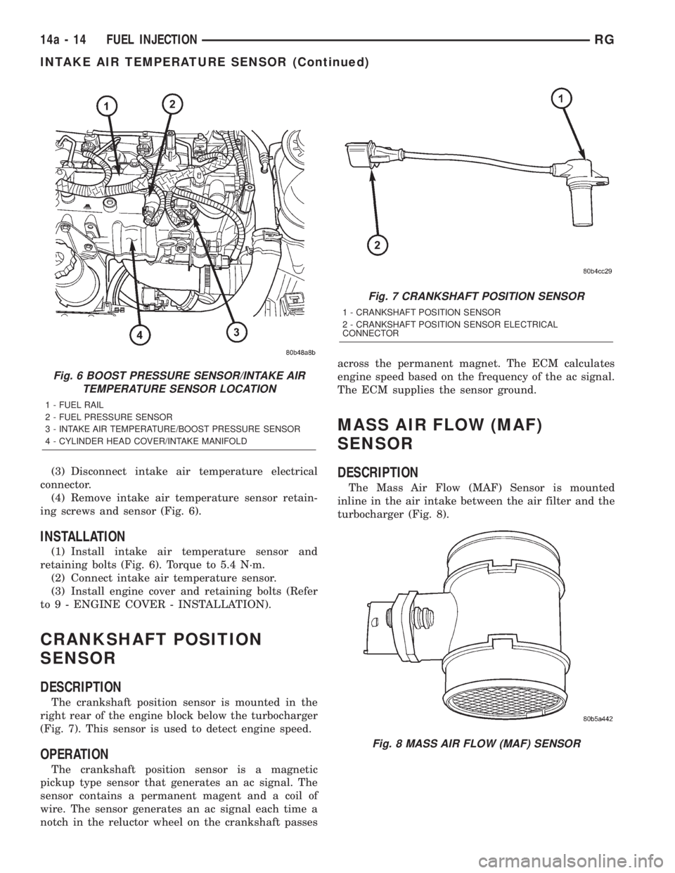
(4) Remove intake air temperature sensor retain-
ing screws and sensor (Fig. 6).
INSTALLATION
(1) Install intake air temperature sensor and
retaining bolts (Fig. 6). Torque to 5.4 N´m.
(2) Connect intake air temperature sensor.
(3) Install engine cover and retaining bolts (Refer
to 9 - ENGINE COVER - INSTALLATION).
CRANKSHAFT POSITION
SENSOR
DESCRIPTION
The crankshaft position sensor is mounted in the
right rear of the engine block below the turbocharger
(Fig. 7). This sensor is used to detect engine speed.
OPERATION
The crankshaft position sensor is a magnetic
pickup type sensor that generates an ac signal. The
sensor contains a permanent magent and a coil of
wire. The sensor generates an ac signal each time a
notch in the reluctor wheel on the crankshaft passesacross the permanent magnet. The ECM calculates
engine speed based on the frequency of the ac signal.
The ECM supplies the sensor ground.
MASS AIR FLOW (MAF)
SENSOR
DESCRIPTION
The Mass Air Flow (MAF) Sensor is mounted
inline in the air intake between the air filter and the
turbocharger (Fig. 8).
Fig. 6 BOOST PRESSURE SENSOR/INTAKE AIR
TEMPERATURE SENSOR LOCATION
1 - FUEL RAIL
2 - FUEL PRESSURE SENSOR
3 - INTAKE AIR TEMPERATURE/BOOST PRESSURE SENSOR
4 - CYLINDER HEAD COVER/INTAKE MANIFOLD
Fig. 7 CRANKSHAFT POSITION SENSOR
1 - CRANKSHAFT POSITION SENSOR
2 - CRANKSHAFT POSITION SENSOR ELECTRICAL
CONNECTOR
Fig. 8 MASS AIR FLOW (MAF) SENSOR
14a - 14 FUEL INJECTIONRG
INTAKE AIR TEMPERATURE SENSOR (Continued)