Page 3299 of 4284
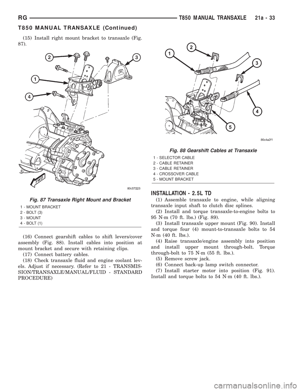
(15) Install right mount bracket to transaxle (Fig.
87).
(16) Connect gearshift cables to shift levers/cover
assembly (Fig. 88). Install cables into position at
mount bracket and secure with retaining clips.
(17) Connect battery cables.
(18) Check transaxle fluid and engine coolant lev-
els. Adjust if necessary. (Refer to 21 - TRANSMIS-
SION/TRANSAXLE/MANUAL/FLUID - STANDARD
PROCEDURE)
INSTALLATION - 2.5L TD
(1) Assemble transaxle to engine, while aligning
transaxle input shaft to clutch disc splines.
(2) Install and torque transaxle-to-engine bolts to
95 N´m (70 ft. lbs.) (Fig. 89).
(3) Install transaxle upper mount (Fig. 90). Install
and torque four (4) mount-to-transaxle bolts to 54
N´m (40 ft. lbs.).
(4) Raise transaxle/engine assembly into position
and install upper mount through-bolt. Torque
through-bolt to 75 N´m (55 ft. lbs.).
(5) Remove screw jack.
(6) Connect back-up lamp switch connector.
(7) Install starter motor into position (Fig. 91).
Install and torque bolts to 54 N´m (40 ft. lbs.).Fig. 87 Transaxle Right Mount and Bracket
1 - MOUNT BRACKET
2 - BOLT (3)
3 - MOUNT
4 - BOLT (1)
Fig. 88 Gearshift Cables at Transaxle
1 - SELECTOR CABLE
2 - CABLE RETAINER
3 - CABLE RETAINER
4 - CROSSOVER CABLE
5 - MOUNT BRACKET
RGT850 MANUAL TRANSAXLE21a-33
T850 MANUAL TRANSAXLE (Continued)
Page 3301 of 4284
(8) Install engine front mount bracket. Install and
torque bracket-to-transaxle bolts to 102 N´m (75 ft.
lbs.). Install and torque bracket-to-engine bolts to 68
N´m (50 ft. lbs.). Torque through-bolt and nut to 68
N´m (50 ft. lbs.).
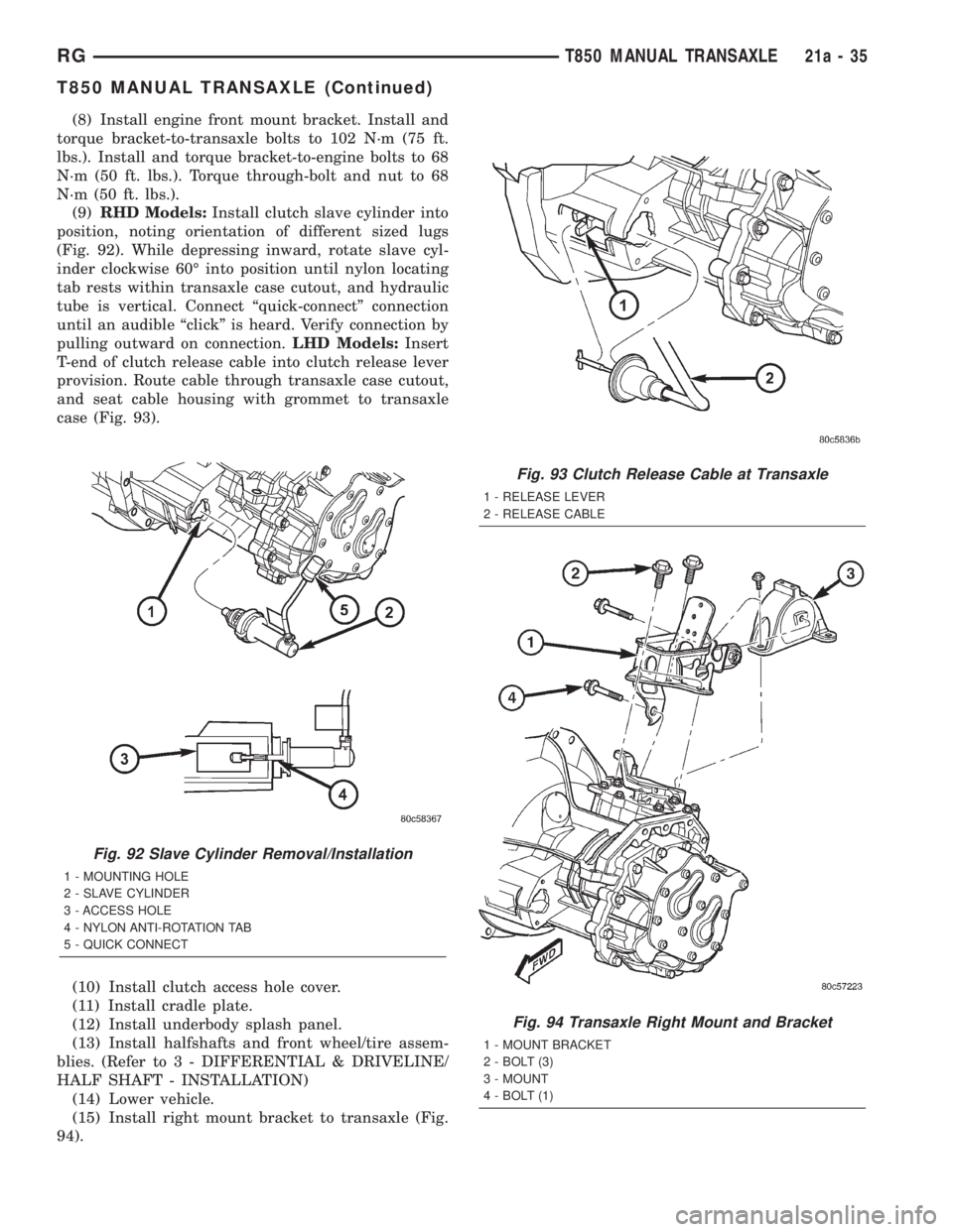
(9)RHD Models:Install clutch slave cylinder into
position, noting orientation of different sized lugs
(Fig. 92). While depressing inward, rotate slave cyl-
inder clockwise 60É into position until nylon locating
tab rests within transaxle case cutout, and hydraulic
tube is vertical. Connect ªquick-connectº connection
until an audible ªclickº is heard. Verify connection by
pulling outward on connection.LHD Models:Insert
T-end of clutch release cable into clutch release lever
provision. Route cable through transaxle case cutout,
and seat cable housing with grommet to transaxle
case (Fig. 93).
(10) Install clutch access hole cover.
(11) Install cradle plate.
(12) Install underbody splash panel.
(13) Install halfshafts and front wheel/tire assem-
blies. (Refer to 3 - DIFFERENTIAL & DRIVELINE/
HALF SHAFT - INSTALLATION)
(14) Lower vehicle.
(15) Install right mount bracket to transaxle (Fig.
94).
Fig. 92 Slave Cylinder Removal/Installation
1 - MOUNTING HOLE
2 - SLAVE CYLINDER
3 - ACCESS HOLE
4 - NYLON ANTI-ROTATION TAB
5 - QUICK CONNECT
Fig. 93 Clutch Release Cable at Transaxle
1 - RELEASE LEVER
2 - RELEASE CABLE
Fig. 94 Transaxle Right Mount and Bracket
1 - MOUNT BRACKET
2 - BOLT (3)
3 - MOUNT
4 - BOLT (1)
RGT850 MANUAL TRANSAXLE21a-35
T850 MANUAL TRANSAXLE (Continued)
Page 3303 of 4284
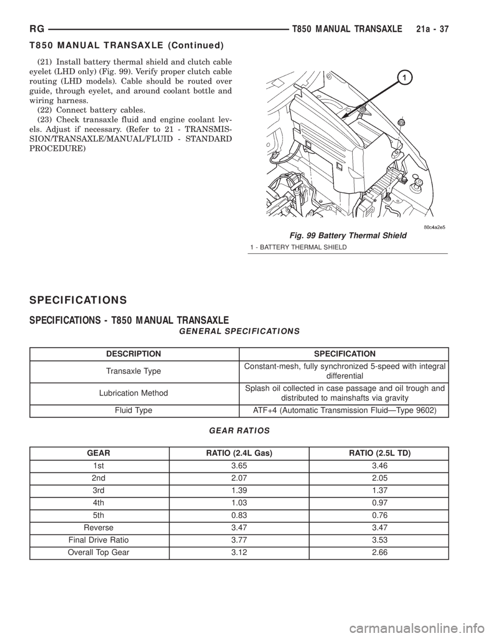
(21) Install battery thermal shield and clutch cable
eyelet (LHD only) (Fig. 99). Verify proper clutch cable
routing (LHD models). Cable should be routed over
guide, through eyelet, and around coolant bottle and
wiring harness.
(22) Connect battery cables.
(23) Check transaxle fluid and engine coolant lev-
els. Adjust if necessary. (Refer to 21 - TRANSMIS-
SION/TRANSAXLE/MANUAL/FLUID - STANDARD
PROCEDURE)
SPECIFICATIONS
SPECIFICATIONS - T850 MANUAL TRANSAXLE
GENERAL SPECIFICATIONS
DESCRIPTION SPECIFICATION
Transaxle TypeConstant-mesh, fully synchronized 5-speed with integral
differential
Lubrication MethodSplash oil collected in case passage and oil trough and
distributed to mainshafts via gravity
Fluid Type ATF+4 (Automatic Transmission FluidÐType 9602)
GEAR RATIOS
GEAR RATIO (2.4L Gas) RATIO (2.5L TD)
1st 3.65 3.46
2nd 2.07 2.05
3rd 1.39 1.37
4th 1.03 0.97
5th 0.83 0.76
Reverse 3.47 3.47
Final Drive Ratio 3.77 3.53
Overall Top Gear 3.12 2.66
Fig. 99 Battery Thermal Shield
1 - BATTERY THERMAL SHIELD
RGT850 MANUAL TRANSAXLE21a-37
T850 MANUAL TRANSAXLE (Continued)
Page 3322 of 4284
(16) Remove crossover cable retainer clip and dis-
engage cable from mount bracket (Fig. 150).
(17) Raise vehicle on hoist.
(18) Remove crossover cable from engine compart-
ment, then remove cable from passenger compart-
ment through opening in floor pan.
INSTALLATION
(1) From underneath vehicle, install gearshift
crossover cable into passenger compartment throughfloor pan hole. Install remainder of cable into posi-
tion in engine compartment.
(2) Lower vehicle.
(3) Install crossover cable to mount bracket and
secure with retainer clip (Fig. 151).
(4) Install cable to transaxle crossover lever (Fig.
151).
Fig. 146 Battery Thermal Shield
1 - BATTERY THERMAL SHIELD
Fig. 147 Battery and Hold-Down Clamp
1 - BATTERY
2 - HOLD-DOWN CLAMP
Fig. 148 Battery Tray
1 - BATTERY TRAY
Fig. 149 Coolant Recovery Bottle Bracket
1 - COOLANT RECOVERY BOTTLE BRACKET
2 - NUT
3 - MOUNT BRACKET
21a - 56 T850 MANUAL TRANSAXLERG
GEARSHIFT CABLE - CROSSOVER (Continued)
Page 3327 of 4284
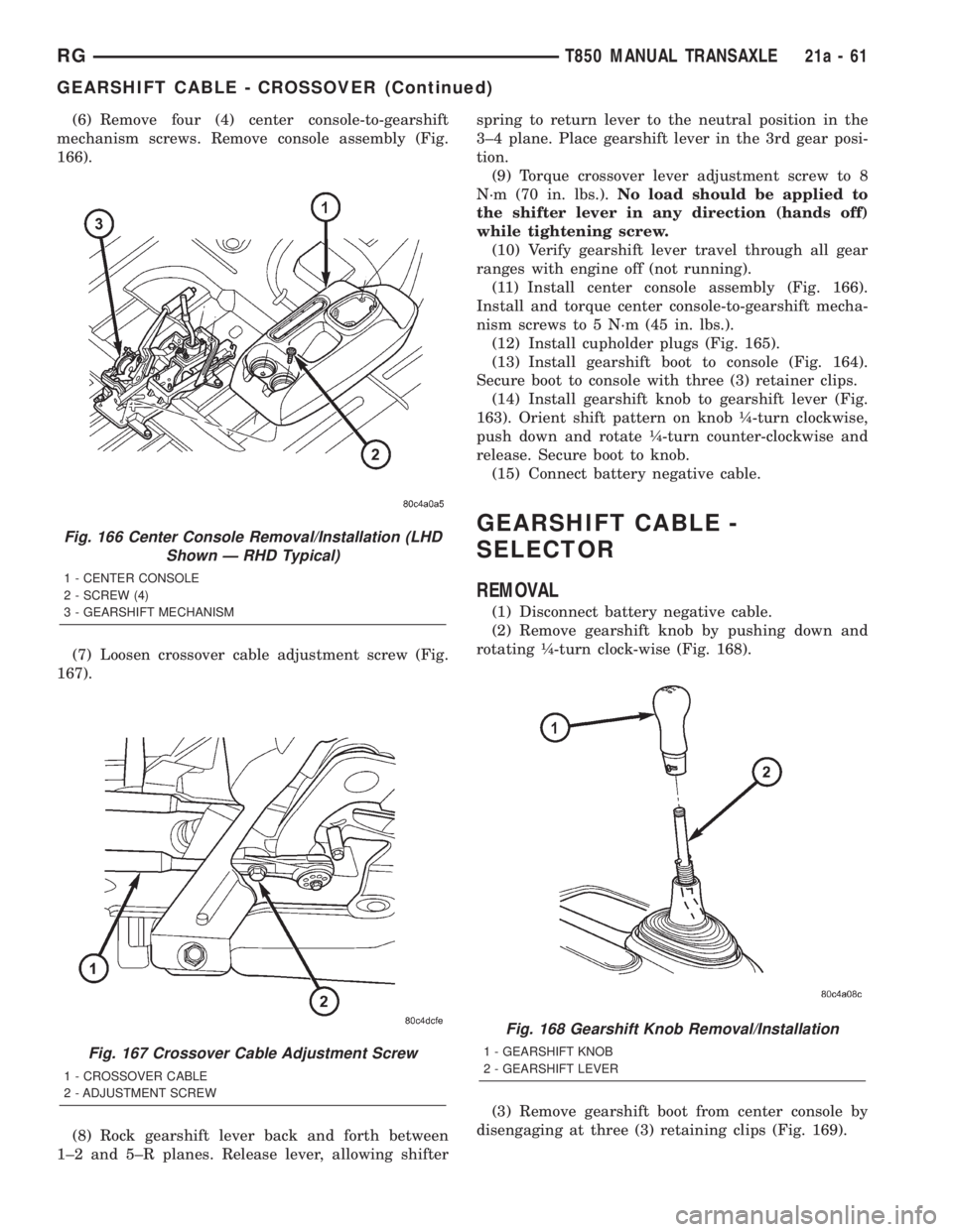
(6) Remove four (4) center console-to-gearshift
mechanism screws. Remove console assembly (Fig.
166).
(7) Loosen crossover cable adjustment screw (Fig.
167).
(8) Rock gearshift lever back and forth between
1±2 and 5±R planes. Release lever, allowing shifterspring to return lever to the neutral position in the
3±4 plane. Place gearshift lever in the 3rd gear posi-
tion.
(9) Torque crossover lever adjustment screw to 8
N´m (70 in. lbs.).No load should be applied to
the shifter lever in any direction (hands off)
while tightening screw.
(10) Verify gearshift lever travel through all gear
ranges with engine off (not running).
(11) Install center console assembly (Fig. 166).
Install and torque center console-to-gearshift mecha-
nism screws to 5 N´m (45 in. lbs.).
(12) Install cupholder plugs (Fig. 165).
(13) Install gearshift boot to console (Fig. 164).
Secure boot to console with three (3) retainer clips.
(14) Install gearshift knob to gearshift lever (Fig.
163). Orient shift pattern on knob ò-turn clockwise,
push down and rotate ò-turn counter-clockwise and
release. Secure boot to knob.
(15) Connect battery negative cable.
GEARSHIFT CABLE -
SELECTOR
REMOVAL
(1) Disconnect battery negative cable.
(2) Remove gearshift knob by pushing down and
rotating ò-turn clock-wise (Fig. 168).
(3) Remove gearshift boot from center console by
disengaging at three (3) retaining clips (Fig. 169).
Fig. 166 Center Console Removal/Installation (LHD
Shown Ð RHD Typical)
1 - CENTER CONSOLE
2 - SCREW (4)
3 - GEARSHIFT MECHANISM
Fig. 167 Crossover Cable Adjustment Screw
1 - CROSSOVER CABLE
2 - ADJUSTMENT SCREW
Fig. 168 Gearshift Knob Removal/Installation
1 - GEARSHIFT KNOB
2 - GEARSHIFT LEVER
RGT850 MANUAL TRANSAXLE21a-61
GEARSHIFT CABLE - CROSSOVER (Continued)
Page 3329 of 4284
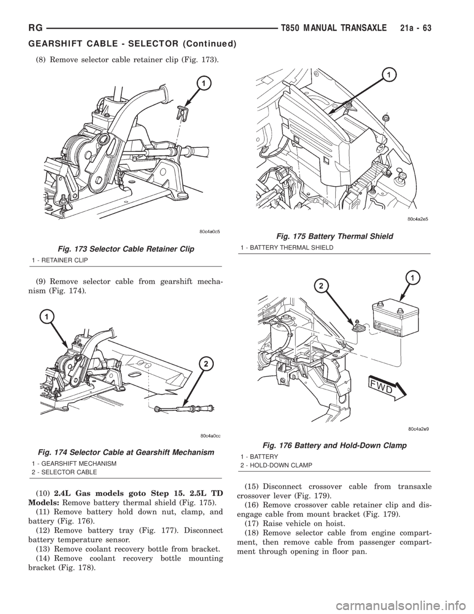
(8) Remove selector cable retainer clip (Fig. 173).
(9) Remove selector cable from gearshift mecha-
nism (Fig. 174).
(10)2.4L Gas models goto Step 15. 2.5L TD
Models:Remove battery thermal shield (Fig. 175).
(11) Remove battery hold down nut, clamp, and
battery (Fig. 176).
(12) Remove battery tray (Fig. 177). Disconnect
battery temperature sensor.
(13) Remove coolant recovery bottle from bracket.
(14) Remove coolant recovery bottle mounting
bracket (Fig. 178).(15) Disconnect crossover cable from transaxle
crossover lever (Fig. 179).
(16) Remove crossover cable retainer clip and dis-
engage cable from mount bracket (Fig. 179).
(17) Raise vehicle on hoist.
(18) Remove selector cable from engine compart-
ment, then remove cable from passenger compart-
ment through opening in floor pan.
Fig. 173 Selector Cable Retainer Clip
1 - RETAINER CLIP
Fig. 174 Selector Cable at Gearshift Mechanism
1 - GEARSHIFT MECHANISM
2 - SELECTOR CABLE
Fig. 175 Battery Thermal Shield
1 - BATTERY THERMAL SHIELD
Fig. 176 Battery and Hold-Down Clamp
1 - BATTERY
2 - HOLD-DOWN CLAMP
RGT850 MANUAL TRANSAXLE21a-63
GEARSHIFT CABLE - SELECTOR (Continued)
Page 3330 of 4284
INSTALLATION
(1) From underneath vehicle, install gearshift
selector cable into passenger compartment through
floor pan hole. Install remainder of cable into posi-
tion in engine compartment.
(2) Lower vehicle.
(3) Install selector cable to mount bracket and
secure with retainer clip (Fig. 180).(4) Install cable to transaxle selector lever (Fig.
180).
Fig. 177 Battery Tray
1 - BATTERY TRAY
Fig. 178 Coolant Recovery Bottle Bracket
1 - COOLANT RECOVERY BOTTLE BRACKET
2 - NUT
3 - MOUNT BRACKET
Fig. 179 Gearshift Cables at Transaxle
1 - SELECTOR CABLE
2 - CABLE RETAINER
3 - CABLE RETAINER
4 - CROSSOVER CABLE
5 - MOUNT BRACKET
Fig. 180 Gearshift Cables at Transaxle
1 - SELECTOR CABLE
2 - CABLE RETAINER
3 - CABLE RETAINER
4 - CROSSOVER CABLE
5 - MOUNT BRACKET
21a - 64 T850 MANUAL TRANSAXLERG
GEARSHIFT CABLE - SELECTOR (Continued)
Page 3370 of 4284
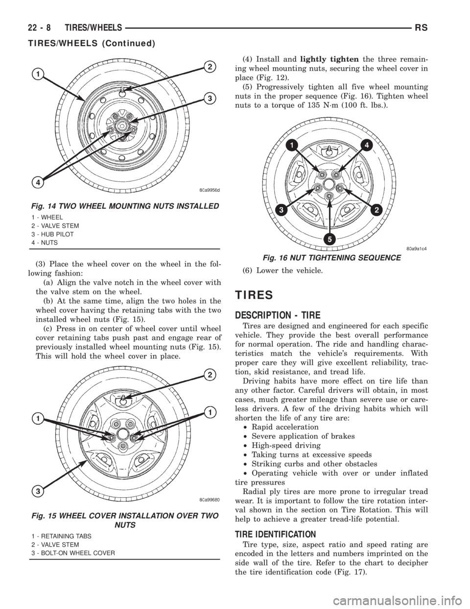
(3) Place the wheel cover on the wheel in the fol-
lowing fashion:
(a) Align the valve notch in the wheel cover with
the valve stem on the wheel.
(b) At the same time, align the two holes in the
wheel cover having the retaining tabs with the two
installed wheel nuts (Fig. 15).
(c) Press in on center of wheel cover until wheel
cover retaining tabs push past and engage rear of
previously installed wheel mounting nuts (Fig. 15).
This will hold the wheel cover in place.(4) Install andlightly tightenthe three remain-
ing wheel mounting nuts, securing the wheel cover in
place (Fig. 12).
(5) Progressively tighten all five wheel mounting
nuts in the proper sequence (Fig. 16). Tighten wheel
nuts to a torque of 135 N´m (100 ft. lbs.).
(6) Lower the vehicle.
TIRES
DESCRIPTION - TIRE
Tires are designed and engineered for each specific
vehicle. They provide the best overall performance
for normal operation. The ride and handling charac-
teristics match the vehicle's requirements. With
proper care they will give excellent reliability, trac-
tion, skid resistance, and tread life.
Driving habits have more effect on tire life than
any other factor. Careful drivers will obtain, in most
cases, much greater mileage than severe use or care-
less drivers. A few of the driving habits which will
shorten the life of any tire are:
²Rapid acceleration
²Severe application of brakes
²High-speed driving
²Taking turns at excessive speeds
²Striking curbs and other obstacles
²Operating vehicle with over or under inflated
tire pressures
Radial ply tires are more prone to irregular tread
wear. It is important to follow the tire rotation inter-
val shown in the section on Tire Rotation. This will
help to achieve a greater tread-life potential.
TIRE IDENTIFICATION
Tire type, size, aspect ratio and speed rating are
encoded in the letters and numbers imprinted on the
side wall of the tire. Refer to the chart to decipher
the tire identification code (Fig. 17).
Fig. 14 TWO WHEEL MOUNTING NUTS INSTALLED
1 - WHEEL
2 - VALVE STEM
3 - HUB PILOT
4 - NUTS
Fig. 15 WHEEL COVER INSTALLATION OVER TWO
NUTS
1 - RETAINING TABS
2 - VALVE STEM
3 - BOLT-ON WHEEL COVER
Fig. 16 NUT TIGHTENING SEQUENCE
22 - 8 TIRES/WHEELSRS
TIRES/WHEELS (Continued)