2001 CHRYSLER VOYAGER engine
[x] Cancel search: enginePage 2859 of 4284

(8) With exhaust manifold and turbocharger
assembly on work bench, remove turbocharger to
exhaust manifold retaining bolts. Separate exhaust
manifold and turbocharger.
CLEANING
All old gaskets should be inspected for any tears or
signs of prior leakage. If any gaskets show such indi-
cations, they should be replaced with new gaskets.
All gasket mating surfaces must be cleaned of old
gasket material to produce a smooth and dirt free
sealing surface for the new gasket.
INSTALLATION
(1) Connect exhaust manifold and turbocharger.
Torque nuts to 32.4N´m.
(2) Position new exhaust manifol gasket on
exhaust manifol studs (Fig. 6).
(3) Install exhaust manifold and turbocharger on
engine (Fig. 6). Torque nuts to 32.4N´m.
(4) Connect turbocharger oil supply and return
lines at turbocharger (Fig. 6). Torque oil supply line
to 24.5N´m.
(5) Install exhaust manifold shield (Fig. 6). Torque
bolts to 27.5N´m.
(6) Install engine lift hook (Fig. 6). Torque bolts to
32.4N´m.
(7) Install thermostat to upper radiator hose tube
and turbocharger outlet tube (Fig. 5).
(8) Install engine in vehicle (Refer to 9 - ENGINE
- INSTALLATION).
HEAT SHIELDS
REMOVAL
(1) Remove front wiper unit (Refer to 8 - ELEC-
TRICAL/WIPERS/WASHERS/WIPER MODULE -
REMOVAL).
(2) Remove engine cover (Refer to 9 - ENGINE -
REMOVAL).
(3) Partially drain cooling system (Refer to 7 -
COOLING/ENGINE/COOLANT - STANDARD PRO-
CEDURE).
(4) Remove thermostat housing to upper radiator
hose tube (Fig. 7).
(5) Remove exhaust manifold heat shield retaining
bolts and remove shield (Fig. 8).
Fig. 7 TURBOCHARGER AND COOLANT PIPES
1 - TURBOCHARGER OUTLET PIPE RETAINING BOLT
2 - TURBOCHARGER OUTLET PIPE
3 - ADAPTER HOSE
4 - HEAT SHIELD
5 - HOSE CLAMPS
6 - TURBOCHARGER INLET PIPE RETAINING BOLT
7 - TURBOCHARGER INLET PIPE
8 - ADAPTER HOSE
9 - HOSE CLAMPS
10 - CLAMP
11 - EGR VALVE TO INTAKE AIR INLET PIPE
12 - CLAMP
13 - THERMOSTAT HOUSING TO UPPER RADIATOR HOSE
PIPE
RGEXHAUST SYSTEM AND TURBOCHARGER11a-5
TURBOCHARGER (Continued)
Page 2860 of 4284
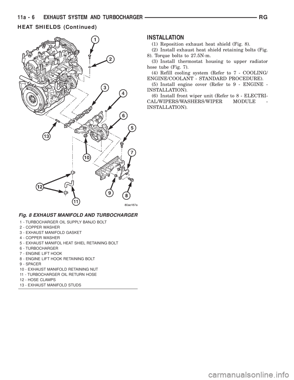
INSTALLATION
(1) Reposition exhaust heat shield (Fig. 8).
(2) Install exhaust heat shield retaining bolts (Fig.
8). Torque bolts to 27.5N´m.
(3) Install thermostat housing to upper radiator
hose tube (Fig. 7).
(4) Refill cooling system (Refer to 7 - COOLING/
ENGINE/COOLANT - STANDARD PROCEDURE).
(5) Install engine cover (Refer to 9 - ENGINE -
INSTALLATION).
(6) Install front wiper unit (Refer to 8 - ELECTRI-
CAL/WIPERS/WASHERS/WIPER MODULE -
INSTALLATION).
Fig. 8 EXHAUST MANIFOLD AND TURBOCHARGER
1 - TURBOCHARGER OIL SUPPLY BANJO BOLT
2 - COPPER WASHER
3 - EXHAUST MANIFOLD GASKET
4 - COPPER WASHER
5 - EXHAUST MANIFOL HEAT SHIEL RETAINING BOLT
6 - TURBOCHARGER
7 - ENGINE LIFT HOOK
8 - ENGINE LIFT HOOK RETAINING BOLT
9 - SPACER
10 - EXHAUST MANIFOLD RETAINING NUT
11 - TURBOCHARGER OIL RETURN HOSE
12 - HOSE CLAMPS
13 - EXHAUST MANIFOLD STUDS
11a - 6 EXHAUST SYSTEM AND TURBOCHARGERRG
HEAT SHIELDS (Continued)
Page 2866 of 4284
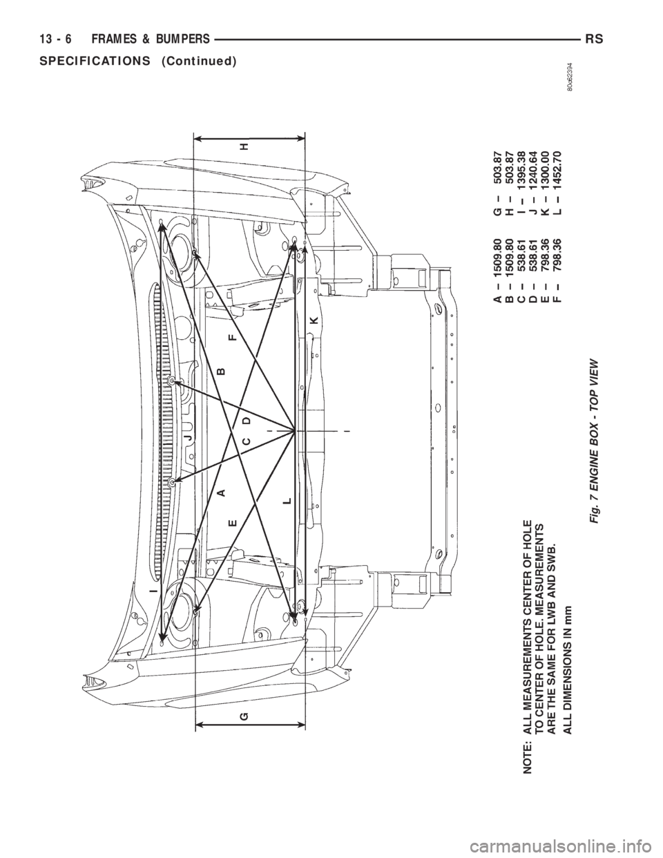
Fig. 7 ENGINE BOX - TOP VIEW
13 - 6 FRAMES & BUMPERSRS
SPECIFICATIONS (Continued)
Page 2867 of 4284
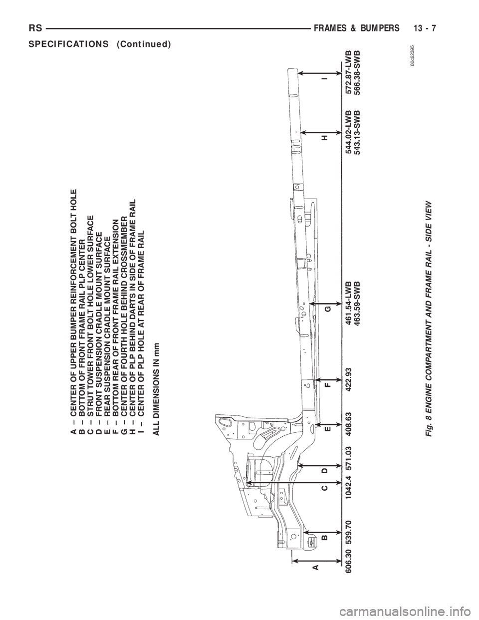
Fig. 8 ENGINE COMPARTMENT AND FRAME RAIL - SIDE VIEW
RSFRAMES & BUMPERS13-7
SPECIFICATIONS (Continued)
Page 2869 of 4284
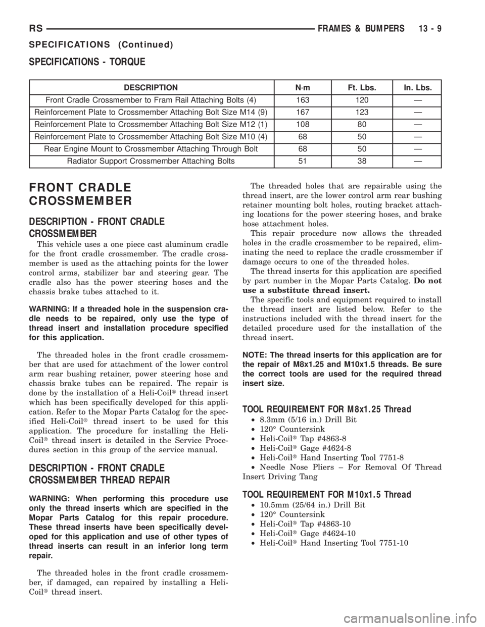
SPECIFICATIONS - TORQUE
DESCRIPTION N´m Ft. Lbs. In. Lbs.
Front Cradle Crossmember to Fram Rail Attaching Bolts (4) 163 120 Ð
Reinforcement Plate to Crossmember Attaching Bolt Size M14 (9) 167 123 Ð
Reinforcement Plate to Crossmember Attaching Bolt Size M12 (1) 108 80 Ð
Reinforcement Plate to Crossmember Attaching Bolt Size M10 (4) 68 50 Ð
Rear Engine Mount to Crossmember Attaching Through Bolt 68 50 Ð
Radiator Support Crossmember Attaching Bolts 51 38 Ð
FRONT CRADLE
CROSSMEMBER
DESCRIPTION - FRONT CRADLE
CROSSMEMBER
This vehicle uses a one piece cast aluminum cradle
for the front cradle crossmember. The cradle cross-
member is used as the attaching points for the lower
control arms, stabilizer bar and steering gear. The
cradle also has the power steering hoses and the
chassis brake tubes attached to it.
WARNING: If a threaded hole in the suspension cra-
dle needs to be repaired, only use the type of
thread insert and installation procedure specified
for this application.
The threaded holes in the front cradle crossmem-
ber that are used for attachment of the lower control
arm rear bushing retainer, power steering hose and
chassis brake tubes can be repaired. The repair is
done by the installation of a Heli-Coiltthread insert
which has been specifically developed for this appli-
cation. Refer to the Mopar Parts Catalog for the spec-
ified Heli-Coiltthread insert to be used for this
application. The procedure for installing the Heli-
Coiltthread insert is detailed in the Service Proce-
dures section in this group of the service manual.
DESCRIPTION - FRONT CRADLE
CROSSMEMBER THREAD REPAIR
WARNING: When performing this procedure use
only the thread inserts which are specified in the
Mopar Parts Catalog for this repair procedure.
These thread inserts have been specifically devel-
oped for this application and use of other types of
thread inserts can result in an inferior long term
repair.
The threaded holes in the front cradle crossmem-
ber, if damaged, can repaired by installing a Heli-
Coiltthread insert.The threaded holes that are repairable using the
thread insert, are the lower control arm rear bushing
retainer mounting bolt holes, routing bracket attach-
ing locations for the power steering hoses, and brake
hose attachment holes.
This repair procedure now allows the threaded
holes in the cradle crossmember to be repaired, elim-
inating the need to replace the cradle crossmember if
damage occurs to one of the threaded holes.
The thread inserts for this application are specified
by part number in the Mopar Parts Catalog.Do not
use a substitute thread insert.
The specific tools and equipment required to install
the thread insert are listed below. Refer to the
instructions included with the thread insert for the
detailed procedure used for the installation of the
thread insert.
NOTE: The thread inserts for this application are for
the repair of M8x1.25 and M10x1.5 threads. Be sure
the correct tools are used for the required thread
insert size.
TOOL REQUIREMENT FOR M8x1.25 Thread
²8.3mm (5/16 in.) Drill Bit
²120É Countersink
²Heli-CoiltTap #4863-8
²Heli-CoiltGage #4624-8
²Heli-CoiltHand Inserting Tool 7751-8
²Needle Nose Pliers ± For Removal Of Thread
Insert Driving Tang
TOOL REQUIREMENT FOR M10x1.5 Thread
²10.5mm (25/64 in.) Drill Bit
²120É Countersink
²Heli-CoiltTap #4863-10
²Heli-CoiltGage #4624-10
²Heli-CoiltHand Inserting Tool 7751-10
RSFRAMES & BUMPERS13-9
SPECIFICATIONS (Continued)
Page 2870 of 4284
²Needle Nose Pliers ± For Removal Of Thread
Insert Driving Tang
REMOVAL
The front cradle crossmember must be installed in
the design location to achieve proper front end sus-
pension alignment. If the cradle crossmember is
removed without applying reference marks on the
frame rails, align the cradle crossmember according
to the dimensions provided in this group.
NOTE: If the caged nuts in the frame rails become
damaged and cannot be reused, a replacement nut
can be obtained through MoparT.
REMOVAL
(1) Disconnect battery negative cable.
(2) Remove steering column lower cover from
instrument panel. Refer to Group 8E, Instrument
Panel and Systems.
(3) Remove knee blocker reinforcement. Refer to
Group 8E, Instrument Panel and Systems.
(4) Position steering so front wheels are straight
ahead.
CAUTION: Do not rotate steering wheel after disen-
gaging lower coupling from steering gear, damage
to air bag clock spring can result.
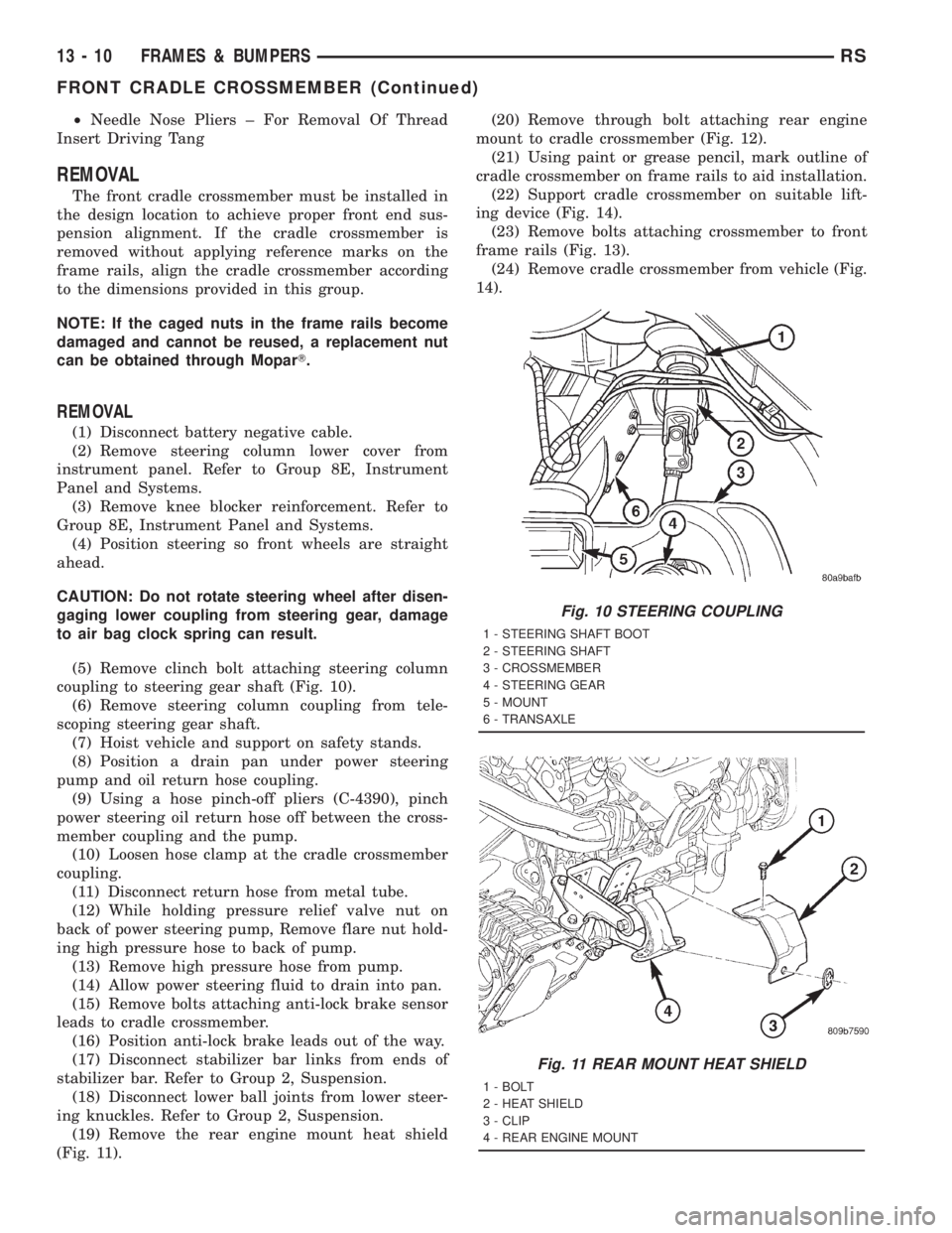
(5) Remove clinch bolt attaching steering column
coupling to steering gear shaft (Fig. 10).
(6) Remove steering column coupling from tele-
scoping steering gear shaft.
(7) Hoist vehicle and support on safety stands.
(8) Position a drain pan under power steering
pump and oil return hose coupling.
(9) Using a hose pinch-off pliers (C-4390), pinch
power steering oil return hose off between the cross-
member coupling and the pump.
(10) Loosen hose clamp at the cradle crossmember
coupling.
(11) Disconnect return hose from metal tube.
(12) While holding pressure relief valve nut on
back of power steering pump, Remove flare nut hold-
ing high pressure hose to back of pump.
(13) Remove high pressure hose from pump.
(14) Allow power steering fluid to drain into pan.
(15) Remove bolts attaching anti-lock brake sensor
leads to cradle crossmember.
(16) Position anti-lock brake leads out of the way.
(17) Disconnect stabilizer bar links from ends of
stabilizer bar. Refer to Group 2, Suspension.
(18) Disconnect lower ball joints from lower steer-
ing knuckles. Refer to Group 2, Suspension.
(19) Remove the rear engine mount heat shield
(Fig. 11).(20) Remove through bolt attaching rear engine
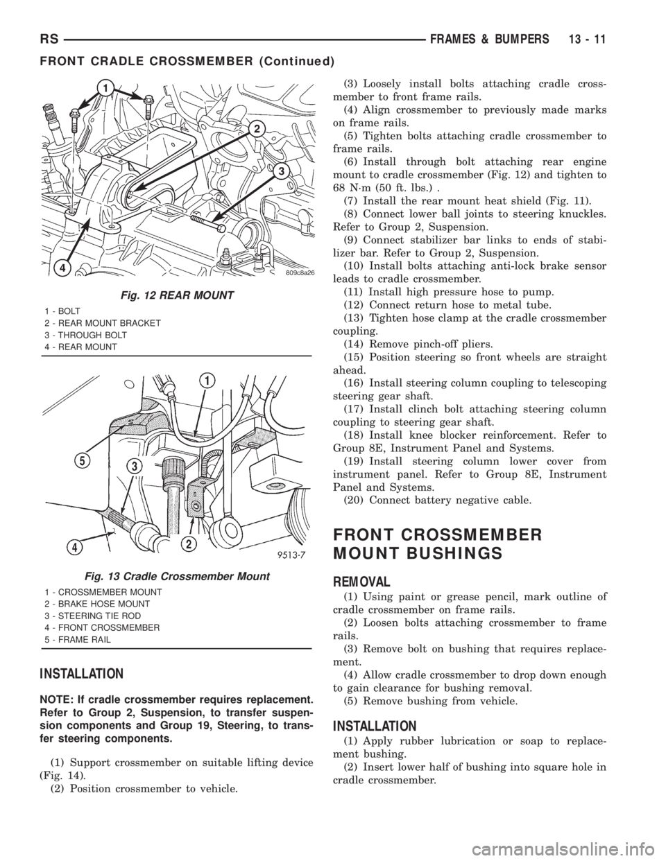
mount to cradle crossmember (Fig. 12).
(21) Using paint or grease pencil, mark outline of
cradle crossmember on frame rails to aid installation.
(22) Support cradle crossmember on suitable lift-
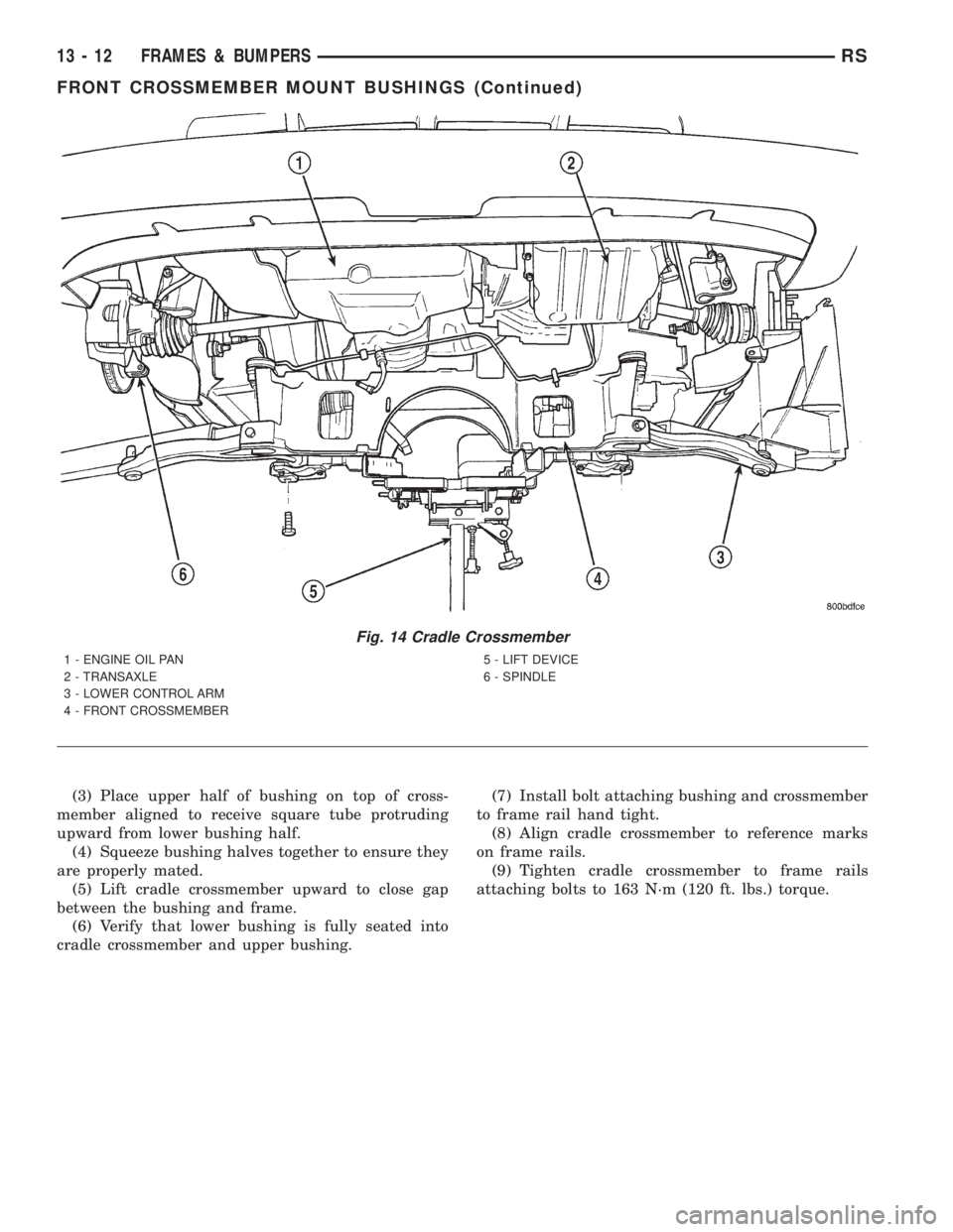
ing device (Fig. 14).
(23) Remove bolts attaching crossmember to front
frame rails (Fig. 13).
(24) Remove cradle crossmember from vehicle (Fig.
14).
Fig. 10 STEERING COUPLING
1 - STEERING SHAFT BOOT
2 - STEERING SHAFT
3 - CROSSMEMBER
4 - STEERING GEAR
5 - MOUNT
6 - TRANSAXLE
Fig. 11 REAR MOUNT HEAT SHIELD
1 - BOLT
2 - HEAT SHIELD
3 - CLIP
4 - REAR ENGINE MOUNT
13 - 10 FRAMES & BUMPERSRS
FRONT CRADLE CROSSMEMBER (Continued)
Page 2871 of 4284
INSTALLATION
NOTE: If cradle crossmember requires replacement.
Refer to Group 2, Suspension, to transfer suspen-
sion components and Group 19, Steering, to trans-
fer steering components.
(1) Support crossmember on suitable lifting device
(Fig. 14).
(2) Position crossmember to vehicle.(3) Loosely install bolts attaching cradle cross-
member to front frame rails.
(4) Align crossmember to previously made marks
on frame rails.
(5) Tighten bolts attaching cradle crossmember to
frame rails.
(6) Install through bolt attaching rear engine
mount to cradle crossmember (Fig. 12) and tighten to
68 N´m (50 ft. lbs.) .
(7) Install the rear mount heat shield (Fig. 11).
(8) Connect lower ball joints to steering knuckles.
Refer to Group 2, Suspension.
(9) Connect stabilizer bar links to ends of stabi-
lizer bar. Refer to Group 2, Suspension.
(10) Install bolts attaching anti-lock brake sensor
leads to cradle crossmember.
(11) Install high pressure hose to pump.
(12) Connect return hose to metal tube.
(13) Tighten hose clamp at the cradle crossmember
coupling.
(14) Remove pinch-off pliers.
(15) Position steering so front wheels are straight
ahead.
(16) Install steering column coupling to telescoping
steering gear shaft.
(17) Install clinch bolt attaching steering column
coupling to steering gear shaft.
(18) Install knee blocker reinforcement. Refer to
Group 8E, Instrument Panel and Systems.
(19) Install steering column lower cover from
instrument panel. Refer to Group 8E, Instrument
Panel and Systems.
(20) Connect battery negative cable.
FRONT CROSSMEMBER
MOUNT BUSHINGS
REMOVAL
(1) Using paint or grease pencil, mark outline of
cradle crossmember on frame rails.
(2) Loosen bolts attaching crossmember to frame
rails.
(3) Remove bolt on bushing that requires replace-
ment.
(4) Allow cradle crossmember to drop down enough
to gain clearance for bushing removal.
(5) Remove bushing from vehicle.
INSTALLATION
(1) Apply rubber lubrication or soap to replace-
ment bushing.
(2) Insert lower half of bushing into square hole in
cradle crossmember.
Fig. 12 REAR MOUNT
1 - BOLT
2 - REAR MOUNT BRACKET
3 - THROUGH BOLT
4 - REAR MOUNT
Fig. 13 Cradle Crossmember Mount
1 - CROSSMEMBER MOUNT
2 - BRAKE HOSE MOUNT
3 - STEERING TIE ROD
4 - FRONT CROSSMEMBER
5 - FRAME RAIL
RSFRAMES & BUMPERS13-11
FRONT CRADLE CROSSMEMBER (Continued)
Page 2872 of 4284
(3) Place upper half of bushing on top of cross-
member aligned to receive square tube protruding
upward from lower bushing half.
(4) Squeeze bushing halves together to ensure they
are properly mated.
(5) Lift cradle crossmember upward to close gap
between the bushing and frame.
(6) Verify that lower bushing is fully seated into
cradle crossmember and upper bushing.(7) Install bolt attaching bushing and crossmember
to frame rail hand tight.
(8) Align cradle crossmember to reference marks
on frame rails.
(9) Tighten cradle crossmember to frame rails
attaching bolts to 163 N´m (120 ft. lbs.) torque.
Fig. 14 Cradle Crossmember
1 - ENGINE OIL PAN
2 - TRANSAXLE
3 - LOWER CONTROL ARM
4 - FRONT CROSSMEMBER5 - LIFT DEVICE
6 - SPINDLE
13 - 12 FRAMES & BUMPERSRS
FRONT CROSSMEMBER MOUNT BUSHINGS (Continued)