Page 13 of 88

Downloaded from www.Manualslib.com manuals search engine
13
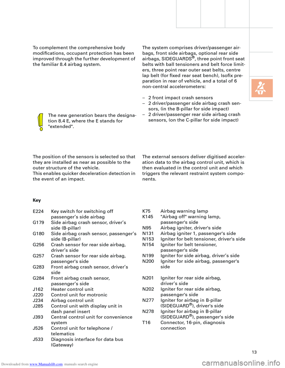
The system comprises driver/passenger air-
bags, front side airbags, optional rear side
airbags, SIDEGUARDS
®
, three point front seat
belts with ball tensioners and belt force limit-
ers, three point rear outer seat belts, centre
lap belt (for fixed rear seat bench), Isofix pre-
paration in rear of vehicle, and a total of 6
non-central accelerometers:
– 2 front impact crash sensors
– 2 driver/passenger side airbag crash sen-
sors, (in the B-pillar for side impact)
– 2 driver/passenger rear side airbag crash
sensors, (on the C-pillar for side impact) To complement the comprehensive body
modifications, occupant protection has been
improved through the further development of
the familiar 8.4 airbag system.
The new generation bears the designa-
tion 8.4 E, where the E stands for
"extended".
The position of the sensors is selected so that
they are installed as near as possible to the
outer structure of the vehicle.
This enables quicker deceleration detection in
the event of an impact.The external sensors deliver digitised acceler-
ation data to the airbag control unit, which is
then evaluated in the control unit and which
triggers the relevant restraint system compo-
nents.
Key
E224 Key switch for switching off
passenger’s side airbag
G179 Side airbag crash sensor, driver’s
side (B-pillar)
G180 Side airbag crash sensor, passenger’s
side (B-pillar)
G256 Crash sensor for rear side airbag,
driver’s side
G257 Crash sensor for rear side airbag,
passenger's side
G283 Front airbag crash sensor, driver’s
side
G284 Front airbag crash sensor,
passenger’s side
J162 Heater control unit
J220 Control unit for motronic
J234 Airbag control unit
J285 Control unit with display unit in
dash panel insert
J393 Central control unit for convenience
system
J526 Control unit for telephone /
telematics
J533 Diagnosis interface for data bus
(Gateway)K75 Airbag warning lamp
K145 "Airbag off" warning lamp,
passenger's side
N95 Airbag igniter, driver's side
N131 Airbag igniter 1, passenger's side
N153 Igniter for belt tensioner, driver's side
N154 Igniter for belt tensioner,
passenger's side
N199 Igniter for side airbag, driver’s side
N200 Igniter for side airbag, passenger's
side
N201 Igniter for rear side airbag,
driver’s side
N202 Igniter for rear side airbag,
passenger's side
N277 Igniter for airbag in B-pillar
(SIDEGUARD
®
), driver's side
N278 Igniter for airbag in B-pillar
(SIDEGUARD
®
), passenger's side
T16 Connector, 16-pin, diagnosis
connection
Page 15 of 88

Downloaded from www.Manualslib.com manuals search engine
15
Re-encoding of the airbag control unit is no
longer possible after the first crash data mes-
sage is stored.
Triggering is performed in two thresholds
depending upon the deceleration value:
– Threshold 1 = belt tensioners only
– Threshold 2 = belt tensioners and airbag(s)
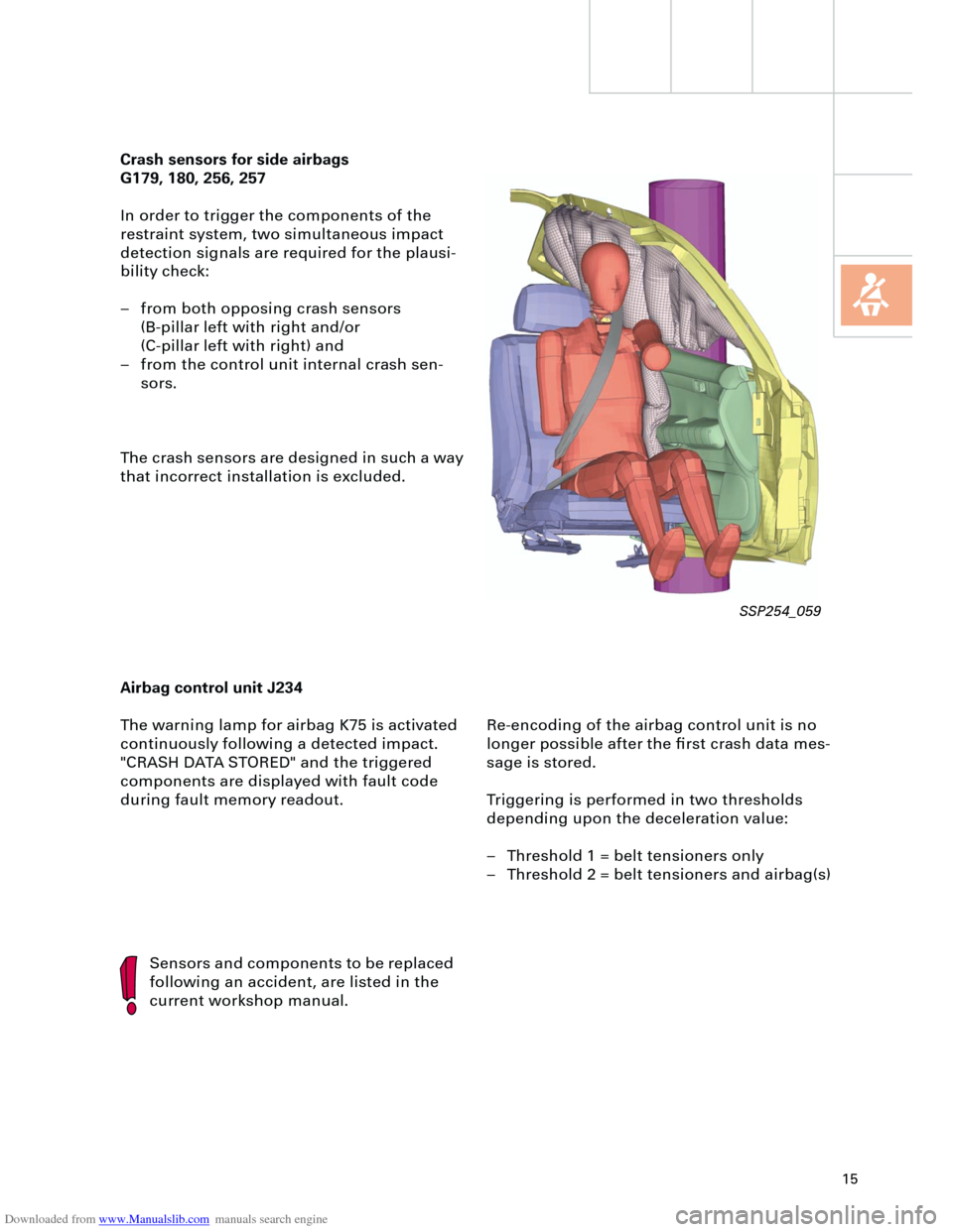
Crash sensors for side airbags
G179, 180, 256, 257
In order to trigger the components of the
restraint system, two simultaneous impact
detection signals are required for the plausi-
bility check:
– from both opposing crash sensors
(B-pillar left with right and/or
(C-pillar left with right) and
– from the control unit internal crash sen-
sors.
The crash sensors are designed in such a way
that incorrect installation is excluded.
Airbag control unit J234
The warning lamp for airbag K75 is activated
continuously following a detected impact.
"CRASH DATA STORED" and the triggered
components are displayed with fault code
during fault memory readout.
Sensors and components to be replaced
following an accident, are listed in the
current workshop manual.
SSP254_059
Page 36 of 88
Downloaded from www.Manualslib.com manuals search engine
36
Front airbag crash sen-
sor, driver’s side G283
Vehicle electrical system
Electrical system
Control unit for
coolant fan,
Stage 1+2 J293Control unit
for ESP J104 Control unit for
telematics J499
Control unit for
mobile phone control
electronics J412
Front airbag crash
sensor, passen-
ger’s side G284
Control unit
for Motronic J220
Control unit for auto-
matic gearbox J217
Control unit for headlamp
range control J431Chip card
reader R99
Steering column
switch module J527
Battery
Control unit with
display in dash panel
insert J285
Page 39 of 88

Downloaded from www.Manualslib.com manuals search engine
39
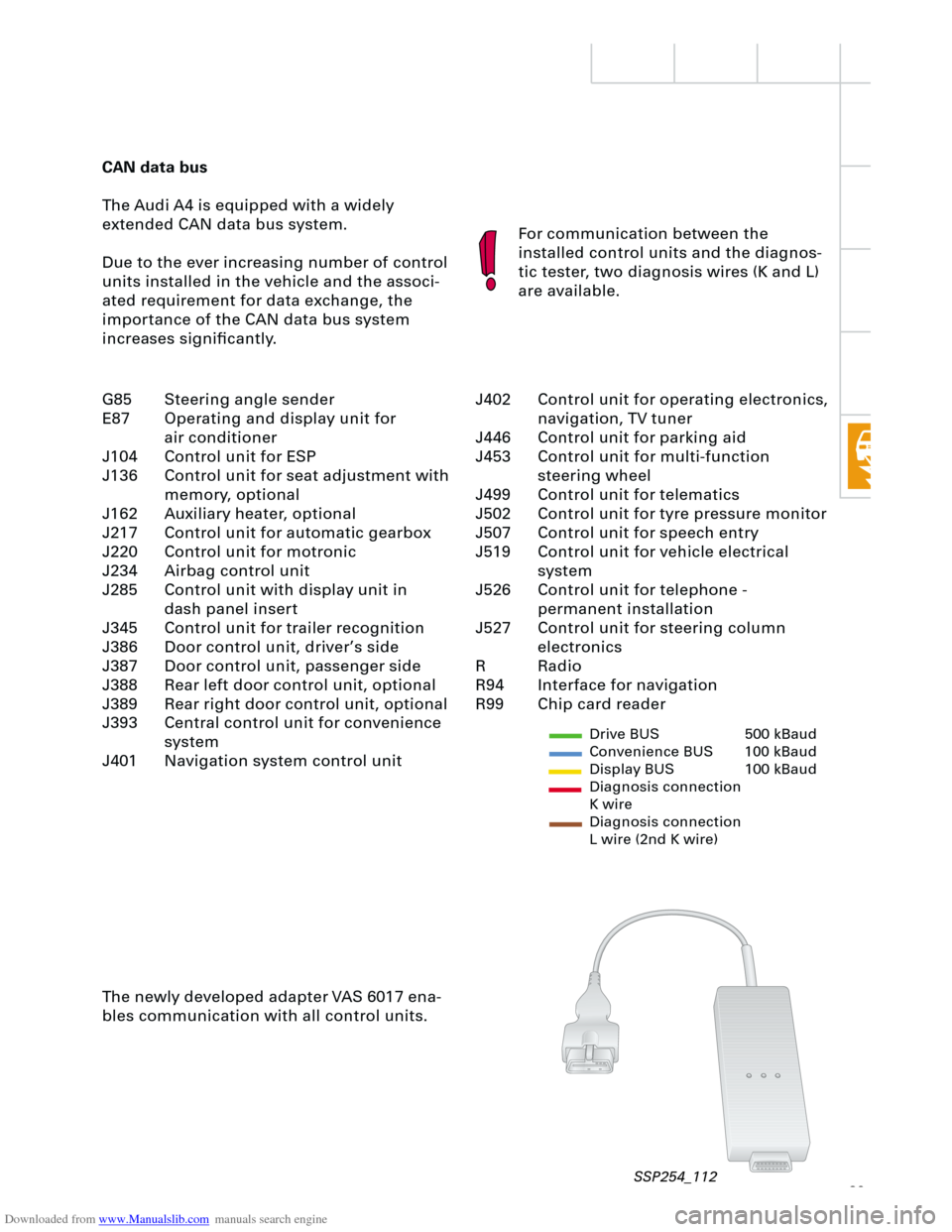
CAN data bus
The Audi A4 is equipped with a widely
extended CAN data bus system.
Due to the ever increasing number of control
units installed in the vehicle and the associ-
ated requirement for data exchange, the
importance of the CAN data bus system
increases significantly.For communication between the
installed control units and the diagnos-
tic tester, two diagnosis wires (K and L)
are available.
The newly developed adapter VAS 6017 ena-
bles communication with all control units.
Drive BUS 500 kBaud
Convenience BUS 100 kBaud
Display BUS 100 kBaud
Diagnosis connection
K wire
Diagnosis connection
L wire (2nd K wire)
J402 Control unit for operating electronics,
navigation, TV tuner
J446 Control unit for parking aid
J453 Control unit for multi-function
steering wheel
J499 Control unit for telematics
J502 Control unit for tyre pressure monitor
J507 Control unit for speech entry
J519 Control unit for vehicle electrical
system
J526 Control unit for telephone -
permanent installation
J527 Control unit for steering column
electronics
R Radio
R94 Interface for navigation
R99 Chip card reader G85 Steering angle sender
E87 Operating and display unit for
air conditioner
J104 Control unit for ESP
J136 Control unit for seat adjustment with
memory, optional
J162 Auxiliary heater, optional
J217 Control unit for automatic gearbox
J220 Control unit for motronic
J234 Airbag control unit
J285 Control unit with display unit in
dash panel insert
J345 Control unit for trailer recognition
J386 Door control unit, driver’s side
J387 Door control unit, passenger side
J388 Rear left door control unit, optional
J389 Rear right door control unit, optional
J393 Central control unit for convenience
system
J401 Navigation system control unit
SSP254_112
Page 40 of 88
Downloaded from www.Manualslib.com manuals search engine
40
Electrical system
Setting buttons for digital clock,
date and instrument illuminationAuto-check system
Call-up button for
service interval
indicatorReset button for trip
recorder
Dash panel insert
There are two dash panel insert versions:
– "lowline"
– "highline"
The "highline" version is equipped with a
high-quality colour display for the driver infor-
mation system and is installed in vehicles
with navigation systems as well as telematics.The dash panel insert of the new Audi A4 is
equipped with
– the gateway for linking the three data bus
systems: drive, convenience, information
– and the immobiliser III.
Cruise control system ON
SSP254_012
Page 41 of 88
Downloaded from www.Manualslib.com manuals search engine
41
In order to ensure good signal reception for
the radio clock, the receiver is installed in the
rear bumper bar. User prompt in the centre display via the con-
trol switch in the centre console, is only avail-
able in vehicles with
– navigation system ("highline" version only)
and/or
– telematics and/or
– auxiliary heater and/or
– tyre pressure monitoring.
The optional driver information system
includes the following functions:
– radio clock
– auto-check system
– on-board computer.
The km range is indicated in the basic ver-
sion.
Ear
th
Radio signal
+ 5
V
SSP254_104
SSP254_108
Page 42 of 88
Downloaded from www.Manualslib.com manuals search engine
42
The Audi A4 quattro is equipped with two fuel
gauge senders G and G169.
Sender G registers the lower, and sender
G169 the upper partial volume in the fuel
tank.
The signals from senders G and G169 are
evaluated separately. The calculated litre
values are then added and displayed. A new feature of the Auto-Check system
is the position-dependent bulb monitor display.
The fault message is transmitted from the vehi-
cle electrical system control unit J519, via the
convenience data bus, to the dash panel insert
J285 and appears on the centre display.
Electrical system
Fuel gauge
sender 2, G169 Fuel gauge
sender G
SSP254_123
Control unit with
display unit in dash
panel processor J285
Control unit for vehicle
electrical system J519 Convenience data
bus
SSP254_118
SSP254_125
Page 43 of 88

Downloaded from www.Manualslib.com manuals search engine
43
A further innovation is the display of the max-
imum and minimum engine oil levels in the
measured value block after the most recent
service operation.
The adaptation of the mileage/kilometre read-
ing after replacement of the dash panel
insert, is possible (several attempts) up to a
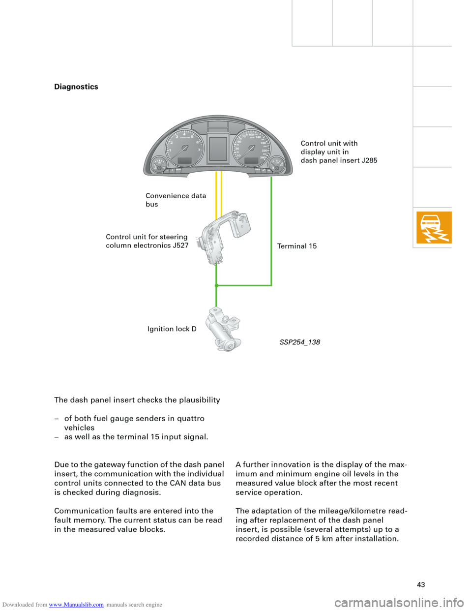
recorded distance of 5 km after installation. The dash panel insert checks the plausibility
– of both fuel gauge senders in quattro
vehicles
– as well as the terminal 15 input signal.
Due to the gateway function of the dash panel
insert, the communication with the individual
control units connected to the CAN data bus
is checked during diagnosis.
Communication faults are entered into the
fault memory. The current status can be read
in the measured value blocks.
Control unit with
display unit in
dash panel insert J285
Control unit for steering
column electronics J527
Ignition lock D Convenience data
bus
Terminal 15
Diagnostics
SSP254_138