2001 AUDI A4 heater
[x] Cancel search: heaterPage 3 of 88
Downloaded from www.Manualslib.com manuals search engine
3
Important:
Note
New
Contents
It is not intended as a workshop manual.
The self-study programme will provide you with information on
design and functions.
For maintenance and repair operations it is essential that you
refer to the current technical literature.
Page
Introduction . . . . . . . . . . . . . . . . . . . . . . . . . . . . . . . . . . . . . . . . . . 4
Body . . . . . . . . . . . . . . . . . . . . . . . . . . . . . . . . . . . . . . . . . . . . . . . . 8
Occupant protection . . . . . . . . . . . . . . . . . . . . . . . . . . . . . . . . 12
Engine and gearbox
Running gear
Axles . . . . . . . . . . . . . . . . . . . . . . . . . . . . . . . . . . . . . . . . . . . . . . . . . . . . . . . . . . . . 26
Mechanical unit mountings . . . . . . . . . . . . . . . . . . . . . . . . . . . . . . . . . . . . . . . . . . . 28
Brake system . . . . . . . . . . . . . . . . . . . . . . . . . . . . . . . . . . . . . . . . . . . . . . . . . . . . . . . 29
Brake assistance . . . . . . . . . . . . . . . . . . . . . . . . . . . . . . . . . . . . . . . . . . . . . . . . . . . . 32
Vehicle electrical system . . . . . . . . . . . . . . . . . . . . . . . . . . . . . . . . . . . . . . . . . . . . . . 36
CAN BUS system . . . . . . . . . . . . . . . . . . . . . . . . . . . . . . . . . . . . . . . . . . . . . . . . . . . . 38
Dash panel insert . . . . . . . . . . . . . . . . . . . . . . . . . . . . . . . . . . . . . . . . . . . . . . . . . . . . 40
Steering column switch module . . . . . . . . . . . . . . . . . . . . . . . . . . . . . . . . . . . . . . . .44
Function circuit diagram . . . . . . . . . . . . . . . . . . . . . . . . . . . . . . . . . . . . . . . 46
Control unit for vehicle electrical system . . . . . . . . . . . . . . . . . . . . . . . . . . . . . . . . 48
Function circuit diagram for "lowline" version . . . . . . . . . . . . . . . . . . . . . 50
Function circuit diagram for "highline" version . . . . . . . . . . . . . . . . . . . . 52
Convenience system . . . . . . . . . . . . . . . . . . . . . . . . . . . . . . . . . . . . . . . . . . . . . . . . . 58
Anti-theft alarm system . . . . . . . . . . . . . . . . . . . . . . . . . . . . . . . . . . . . . . . . . . . . . . . 63
Radio - chorus II, concert II and symphony II . . . . . . . . . . . . . . . . . . . . . . . . . . . . . 65
Navigation IV and Navigation Plus-D . . . . . . . . . . . . . . . . . . . . . . . . . . . . . . . . . . . . 69
Multi-communication bar . . . . . . . . . . . . . . . . . . . . . . . . . . . . . . . . . . . . . . . . . . . . . 72
Electric logbook "Audi Logbook" . . . . . . . . . . . . . . . . . . . . . . . . . . . . . . . . . . . . . . . 74
Heater/AC
Design and function . . . . . . . . . . . . . . . . . . . . . . . . . . . . . . . . . . . . . . . . . . . . . . . . . 76
7-piston compressor . . . . . . . . . . . . . . . . . . . . . . . . . . . . . . . . . . . . . . . . . . . . . . . . . 77
Air conditioner . . . . . . . . . . . . . . . . . . . . . . . . . . . . . . . . . . . . . . . . . . . . . . . . . . . . . . 78
Glove compartment cooling . . . . . . . . . . . . . . . . . . . . . . . . . . . . . . . . . . . . . . . . . . . 79
Solar roof . . . . . . . . . . . . . . . . . . . . . . . . . . . . . . . . . . . . . . . . . . . . . . . . . . . . . . . . . . . 80
Fresh air blower . . . . . . . . . . . . . . . . . . . . . . . . . . . . . . . . . . . . . . . . . . . . . . . . . . . . . 81
Actuators/sensors . . . . . . . . . . . . . . . . . . . . . . . . . . . . . . . . . . . . . . . . . . . . . . . . . . . 82
Functional diagram for fully automatic air conditioner . . . . . . . . . . . . . . 84
Additional heater . . . . . . . . . . . . . . . . . . . . . . . . . . . . . . . . . . . . . . . . . . . . . . . . . . . . 86 2.0 l R4 and 3.0 l V6 engines (see SSP 255) . . . . . . . . . . . . . . . . . . . . . . . . . . . . . . . 18
Innovations - 2.5 l V6 TDI engine. . . . . . . . . . . . . . . . . . . . . . . . . . . . . . . . . . . . . . . . 19
Innovations - automatic gearbox . . . . . . . . . . . . . . . . . . . . . . . . . . . . . . . . . . . . . . . 23
Electrical system
Page 13 of 88
Downloaded from www.Manualslib.com manuals search engine
13
The system comprises driver/passenger air-
bags, front side airbags, optional rear side
airbags, SIDEGUARDS
®
, three point front seat
belts with ball tensioners and belt force limit-
ers, three point rear outer seat belts, centre
lap belt (for fixed rear seat bench), Isofix pre-
paration in rear of vehicle, and a total of 6
non-central accelerometers:
– 2 front impact crash sensors
– 2 driver/passenger side airbag crash sen-
sors, (in the B-pillar for side impact)
– 2 driver/passenger rear side airbag crash
sensors, (on the C-pillar for side impact) To complement the comprehensive body
modifications, occupant protection has been
improved through the further development of
the familiar 8.4 airbag system.
The new generation bears the designa-
tion 8.4 E, where the E stands for
"extended".
The position of the sensors is selected so that
they are installed as near as possible to the
outer structure of the vehicle.
This enables quicker deceleration detection in
the event of an impact.The external sensors deliver digitised acceler-
ation data to the airbag control unit, which is
then evaluated in the control unit and which
triggers the relevant restraint system compo-
nents.
Key
E224 Key switch for switching off
passenger’s side airbag
G179 Side airbag crash sensor, driver’s
side (B-pillar)
G180 Side airbag crash sensor, passenger’s
side (B-pillar)
G256 Crash sensor for rear side airbag,
driver’s side
G257 Crash sensor for rear side airbag,
passenger's side
G283 Front airbag crash sensor, driver’s
side
G284 Front airbag crash sensor,
passenger’s side
J162 Heater control unit
J220 Control unit for motronic
J234 Airbag control unit
J285 Control unit with display unit in
dash panel insert
J393 Central control unit for convenience
system
J526 Control unit for telephone /
telematics
J533 Diagnosis interface for data bus
(Gateway)K75 Airbag warning lamp
K145 "Airbag off" warning lamp,
passenger's side
N95 Airbag igniter, driver's side
N131 Airbag igniter 1, passenger's side
N153 Igniter for belt tensioner, driver's side
N154 Igniter for belt tensioner,
passenger's side
N199 Igniter for side airbag, driver’s side
N200 Igniter for side airbag, passenger's
side
N201 Igniter for rear side airbag,
driver’s side
N202 Igniter for rear side airbag,
passenger's side
N277 Igniter for airbag in B-pillar
(SIDEGUARD
®
), driver's side
N278 Igniter for airbag in B-pillar
(SIDEGUARD
®
), passenger's side
T16 Connector, 16-pin, diagnosis
connection
Page 17 of 88
Downloaded from www.Manualslib.com manuals search engine
17
Crash signal processing
There are two separate crash signal outputs:
One crash signal is output via the conven-
tional wiring and triggers the following func-
tions:
– Transmitting an emergency call via the
control unit for telephone/telematics J526
(optional)
– unlocking the vehicle,
– Switch on interior light
(switch must be set to door contact),
– switching on hazard warning lights via the
central convenience electronics J393.
The auxiliary heater J162 (optional) is
switched off by the central convenience
electronics J393 via a CAN convenience
message.
The second crash signal output functions via
the convenience CAN bus, which switches off
the engine fuel supply via the engine control
unit J220.
Page 39 of 88
Downloaded from www.Manualslib.com manuals search engine
39
CAN data bus
The Audi A4 is equipped with a widely
extended CAN data bus system.
Due to the ever increasing number of control
units installed in the vehicle and the associ-
ated requirement for data exchange, the
importance of the CAN data bus system
increases significantly.For communication between the
installed control units and the diagnos-
tic tester, two diagnosis wires (K and L)
are available.
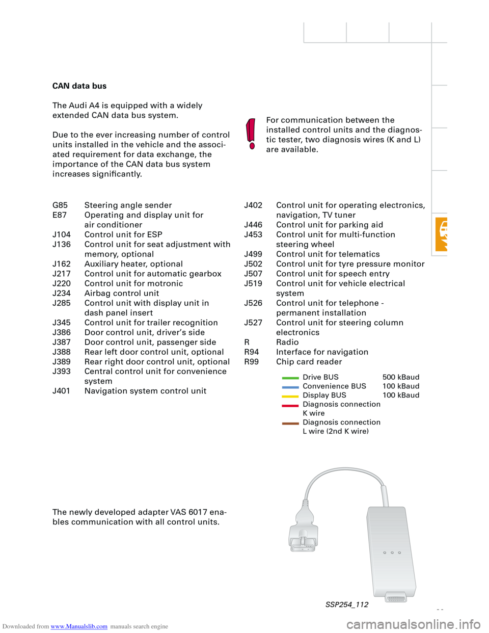
The newly developed adapter VAS 6017 ena-
bles communication with all control units.
Drive BUS 500 kBaud
Convenience BUS 100 kBaud
Display BUS 100 kBaud
Diagnosis connection
K wire
Diagnosis connection
L wire (2nd K wire)
J402 Control unit for operating electronics,
navigation, TV tuner
J446 Control unit for parking aid
J453 Control unit for multi-function
steering wheel
J499 Control unit for telematics
J502 Control unit for tyre pressure monitor
J507 Control unit for speech entry
J519 Control unit for vehicle electrical
system
J526 Control unit for telephone -
permanent installation
J527 Control unit for steering column
electronics
R Radio
R94 Interface for navigation
R99 Chip card reader G85 Steering angle sender
E87 Operating and display unit for
air conditioner
J104 Control unit for ESP
J136 Control unit for seat adjustment with
memory, optional
J162 Auxiliary heater, optional
J217 Control unit for automatic gearbox
J220 Control unit for motronic
J234 Airbag control unit
J285 Control unit with display unit in
dash panel insert
J345 Control unit for trailer recognition
J386 Door control unit, driver’s side
J387 Door control unit, passenger side
J388 Rear left door control unit, optional
J389 Rear right door control unit, optional
J393 Central control unit for convenience
system
J401 Navigation system control unit
SSP254_112
Page 41 of 88
Downloaded from www.Manualslib.com manuals search engine
41
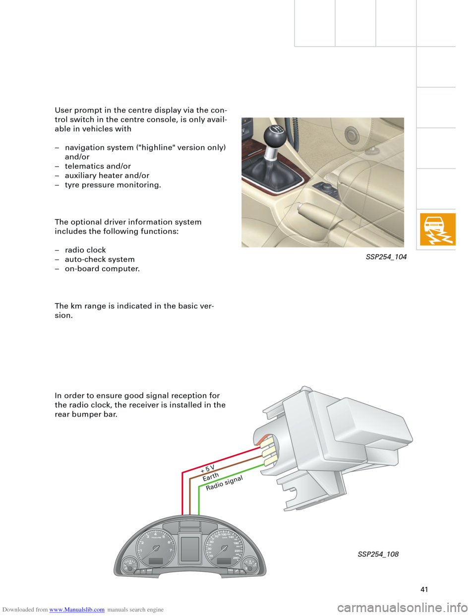
In order to ensure good signal reception for
the radio clock, the receiver is installed in the
rear bumper bar. User prompt in the centre display via the con-
trol switch in the centre console, is only avail-
able in vehicles with
– navigation system ("highline" version only)
and/or
– telematics and/or
– auxiliary heater and/or
– tyre pressure monitoring.
The optional driver information system
includes the following functions:
– radio clock
– auto-check system
– on-board computer.
The km range is indicated in the basic ver-
sion.
Ear
th
Radio signal
+ 5
V
SSP254_104
SSP254_108
Page 76 of 88
Downloaded from www.Manualslib.com manuals search engine
76
Heater/AC
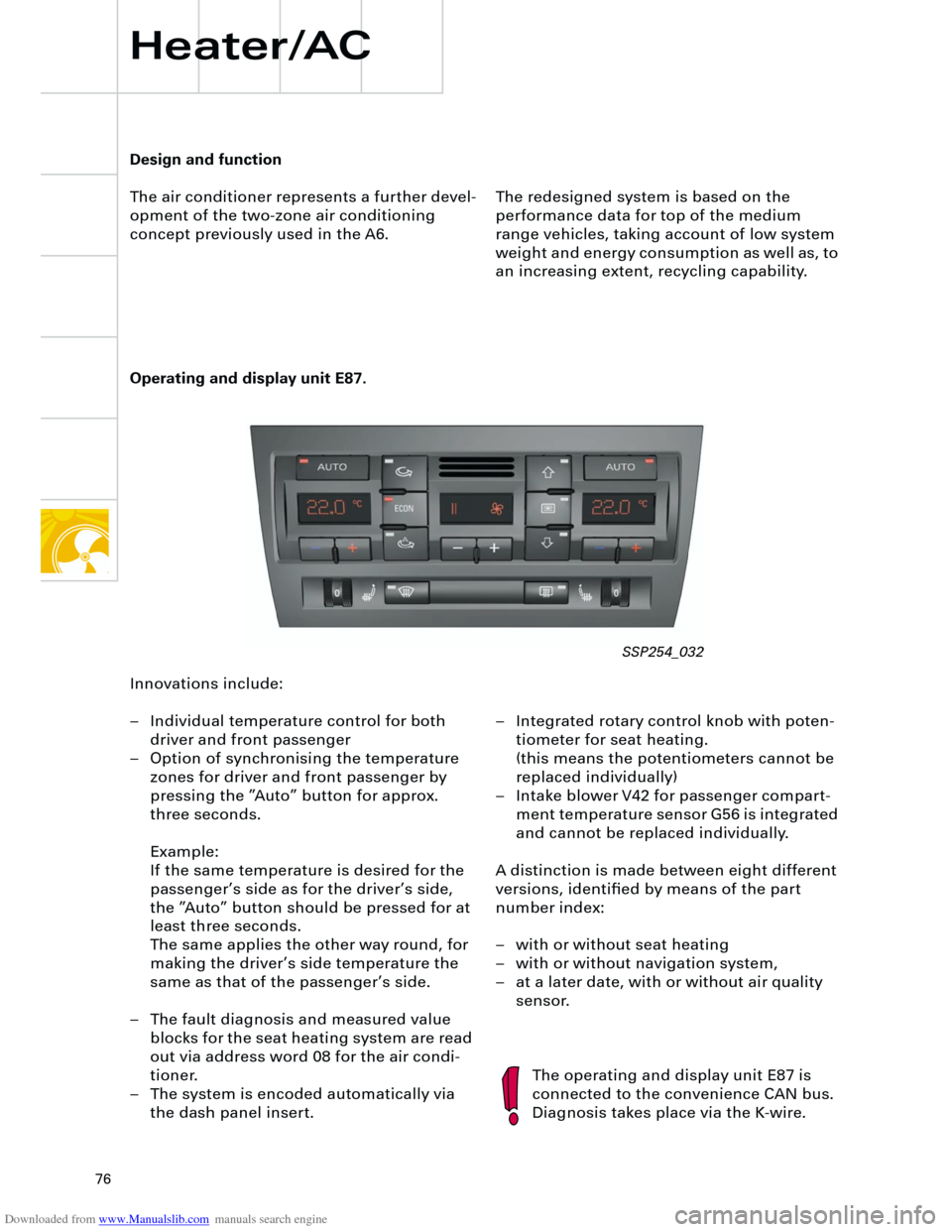
Operating and display unit E87.
The redesigned system is based on the
performance data for top of the medium
range vehicles, taking account of low system
weight and energy consumption as well as, to
an increasing extent, recycling capability.
The operating and display unit E87 is
connected to the convenience CAN bus.
Diagnosis takes place via the K-wire.
Design and function
The air conditioner represents a further devel-
opment of the two-zone air conditioning
concept previously used in the A6.
Innovations include:
– Individual temperature control for both
driver and front passenger
– Option of synchronising the temperature
zones for driver and front passenger by
pressing the ”Auto” button for approx.
three seconds.
Example:
If the same temperature is desired for the
passenger’s side as for the driver’s side,
the ”Auto” button should be pressed for at
least three seconds.
The same applies the other way round, for
making the driver’s side temperature the
same as that of the passenger’s side.
– The fault diagnosis and measured value
blocks for the seat heating system are read
out via address word 08 for the air condi-
tioner.
– The system is encoded automatically via
the dash panel insert.– Integrated rotary control knob with poten-
tiometer for seat heating.
(this means the potentiometers cannot be
replaced individually)
– Intake blower V42 for passenger compart-
ment temperature sensor G56 is integrated
and cannot be replaced individually.
A distinction is made between eight different
versions, identified by means of the part
number index:
– with or without seat heating
– with or without navigation system,
– at a later date, with or without air quality
sensor.
SSP254_032
Page 78 of 88
Downloaded from www.Manualslib.com manuals search engine
78
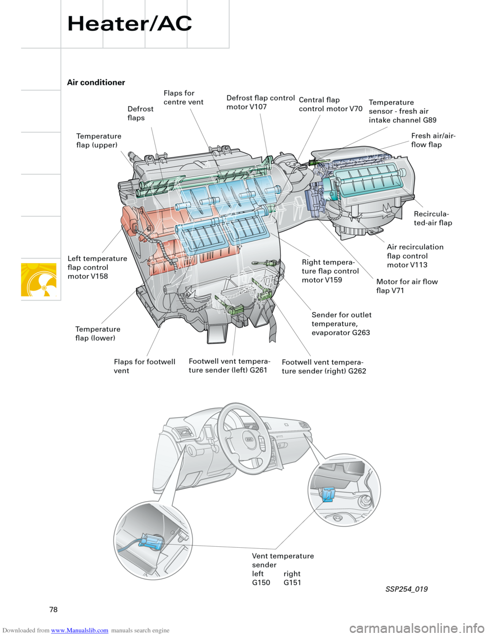
Air conditioner
Heater/AC
Defrost
flaps
Flaps for
centre ventDefrost flap control
motor V107
Temperature
flap (upper)
Left temperature
flap control
motor V158Right tempera-
ture flap control
motor V159
Temperature
flap (lower)
Flaps for footwell
ventFootwell vent tempera-
ture sender (left) G261Footwell vent tempera-
ture sender (right) G262
Sender for outlet
temperature,
evaporator G263 Central flap
control motor V70
Temperature
sensor - fresh air
intake channel G89
Fresh air/air-
flow flap
Air recirculation
flap control
motor V113
Motor for air flow
flap V71
Recircula-
ted-air flap
Vent temperature
sender
left right
G150 G151
SSP254_019
Page 79 of 88
Downloaded from www.Manualslib.com manuals search engine
79
The basic functions of the air conditioner in
the Audi A4 are based on the Audi A6 system
and includes the following features:
– Air-side separation for driver’s and passen-
ger’s side.
– The heat exchanger can be replaced with-
out removing the air conditioner.
– The PTC additional heater element for die-
sel mechanical units can also be replaced
without removing the unit.
– All control motors and potentiometers are
easily accessible and replaceable.
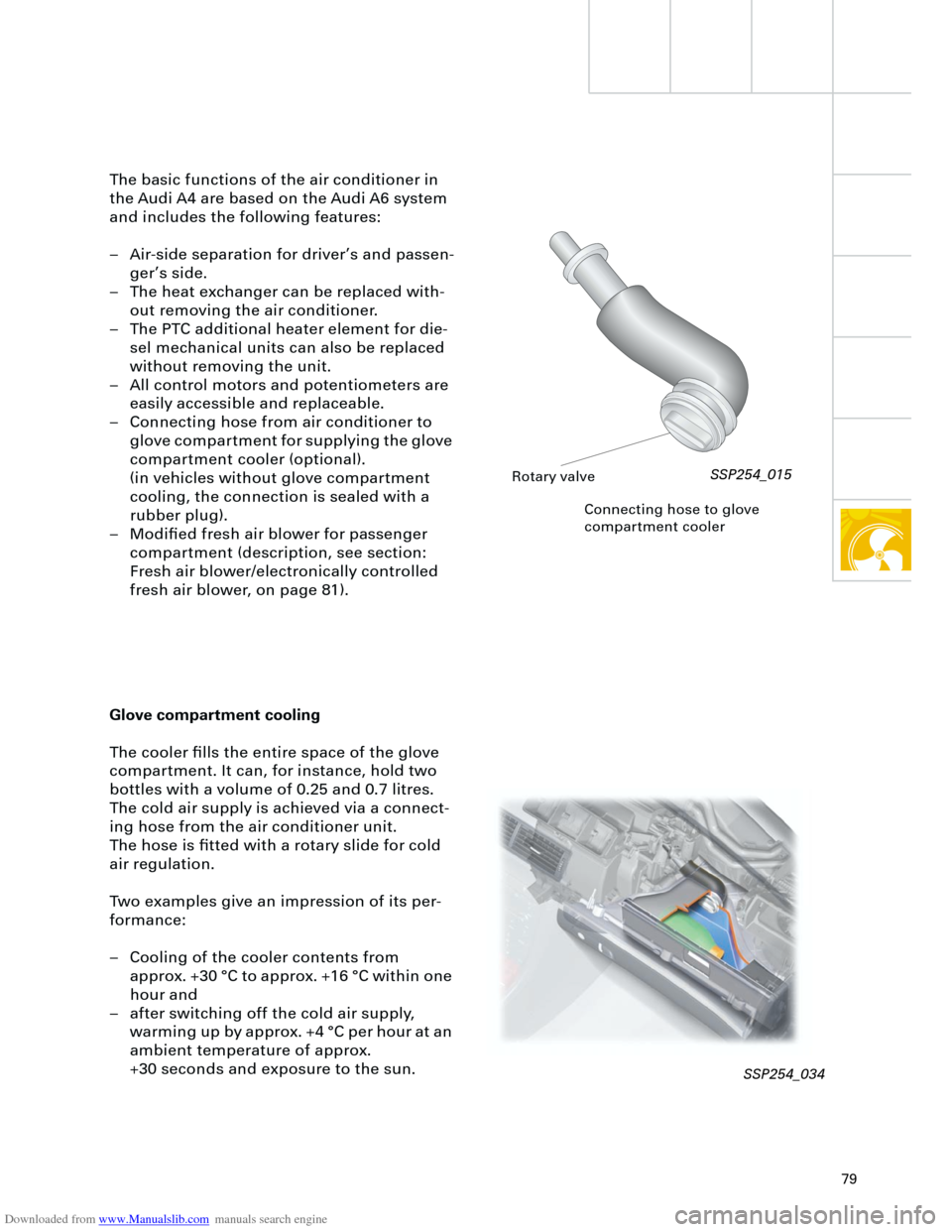
– Connecting hose from air conditioner to
glove compartment for supplying the glove
compartment cooler (optional).
(in vehicles without glove compartment
cooling, the connection is sealed with a
rubber plug).
– Modified fresh air blower for passenger
compartment (description, see section:
Fresh air blower/electronically controlled
fresh air blower, on page 81).
Connecting hose to glove
compartment cooler
Glove compartment cooling
The cooler fills the entire space of the glove
compartment. It can, for instance, hold two
bottles with a volume of 0.25 and 0.7 litres.
The cold air supply is achieved via a connect-
ing hose from the air conditioner unit.
The hose is fitted with a rotary slide for cold
air regulation.
Two examples give an impression of its per-
formance:
– Cooling of the cooler contents from
approx. +30 °C to approx. +16 °C within one
hour and
– after switching off the cold air supply,
warming up by approx. +4 °C per hour at an
ambient temperature of approx.
+30 seconds and exposure to the sun.
Rotary valve
SSP254_015
SSP254_034