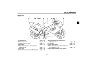
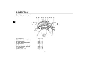
Page 17 of 103
INSTRUMENT AND CONTROL FUNCTIONS
3-3
3
EAU00071
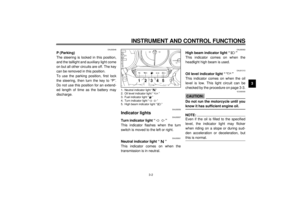
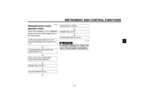
Oil level indicator circuit check
CB-48E
Turn the main switch to “ON” and
the engine stop switch to “ ”.
Oil level indicator light
does not come on.
Oil level indicator light
comes on.Check engine oil level.
Oil level indicator light
comes on.
Oil level indicator light
does not come on.
Engine oil level and
electrical circuit are OK.
Go ahead with riding.
Put the transmission in neutral or
apply the clutch lever, then push
the start switch.
Oil level
is OK.
Supply
engine oil.Oil level
is low.
Ask a Yamaha dealer to
inspect electrical circuit.
E_4sv_Functions.fm Page 3 Tuesday, August 31, 1999 3:42 PM
Page 18 of 103
INSTRUMENT AND CONTROL FUNCTIONS
3-4
3
EAU01154
Fuel indicator light “ ”
When the fuel level drops below ap-
proximately 4.5 L, this light will come
on. When this light comes on, fill the
tank at the first opportunity. This light
circuit can be checked by the proce-
dure on page 3-5.
E_4sv_Functions.fm Page 4 Tuesday, August 31, 1999 3:42 PM
Page 19 of 103
INSTRUMENT AND CONTROL FUNCTIONS
3-5
3
EAU00085
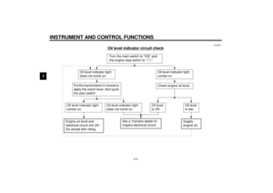
Fuel indicator circuit check
CB-46E
Turn the main switch to “ON” and the
engine stop switch to “ ”.
Fuel indicator light does
not come on.
Fuel indicator light
comes on.Check the fuel level.
Fuel indicator light
comes on.
Fuel indicator light
does not come on.
Fuel level and electrical
circuit are OK.
Go ahead with riding.
Put the transmission in neutral or
apply the clutch lever, then push
the start switch.
Fuel level
is OK.
Supply fuel.Fuel level
is low.
Ask a Yamaha dealer to
inspect electrical circuit.
E_4sv_Functions.fm Page 5 Tuesday, August 31, 1999 3:42 PM
Page 20 of 103
INSTRUMENT AND CONTROL FUNCTIONS
3-6
3
EAU00095
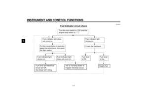
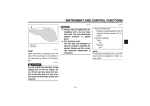
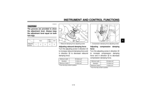
SpeedometerThe speedometer shows riding speed.
This speedometer is equipped with an
odometer and trip odometer. The trip
odometer can be reset to “0” with the
reset knob. Use the trip odometer to
estimate how far you can ride on a tank
of fuel. This information will enable you
to plan fuel stops in the future.
EAU00101
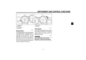
TachometerThis model is equipped with an electric
tachometer so the rider can monitor the
engine speed and keep it within the
ideal power range.
EC000003
CAUTION:@ Do not operate in the red zone.
Red zone: 11,500 r/min and above @
1. Speedometer
2. Odometer
3. Trip odometer
4. Reset knob
1. Tachometer
2. Red zone
E_4sv_Functions.fm Page 6 Tuesday, August 31, 1999 3:42 PM
Page 21 of 103

circuit
l
Exhaust Ultimate")
INSTRUMENT AND CONTROL FUNCTIONS
3-7
3
EAU00106
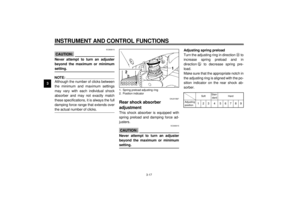
Diagnosis deviceThis model is equipped with a self diag-
nosis for the following circuits.l
Throttle Position Sensor (T.P.S.)
circuit
l
Exhaust Ultimate Power valve
(EXUP) circuit
l
Fuel level indicator circuit
If some trouble should occur in any of
these circuits, the tachometer will re-
peatedly display as follows:
CB-53E
Use this chart to identify what circuit is
faulty according to the specified r/min
displayed.CB-54EIf the tachometer displays as described
above, take note of the specified r/min
and then take your motorcycle to a
Yamaha dealer for repair.
EC000004
CAUTION:@ To prevent engine damage, be sure
to consult a Yamaha dealer as soon
as possible if the tachometer dis-
plays a repeated change in r/min. @
EAU01652
Coolant temperature gaugeThis gauge indicates the coolant tem-
perature when the main switch is on.
The engine operating temperature will
vary with changes in weather and en-
gine load. If the needle points to the red
zone or higher, stop your motorcycle
and let the engine cool. (See page 6-11
for details.)
EC000002
CAUTION:@ When the engine is overheated, do
not continue riding. @
0 r/min for
3 seconds
Specified r/min
for the faulty
circuit for
2.5 seconds
(see chart below)
Current
engine
r/min for
3 seconds
Specified
r/min
Faulty circuit
3,000 r/min
Throttle Position Sensor
(T.P.S.)
7,000 r/min
Exhaust Ultimate Power
valve (EXUP)
8,000 r/min
Fuel level indicator
1. Coolant temperature gauge
2. Red zone
E_4sv_Functions.fm Page 7 Tuesday, August 31, 1999 3:42 PM
Page 22 of 103
INSTRUMENT AND CONTROL FUNCTIONS
3-8
3
EAU00118
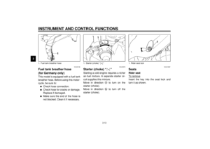
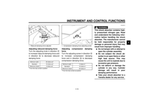
Handlebar switches
EAU00120
Pass switch “PASS”
Press the switch to operate the passing
light.
EAU00121
Dimmer switch
Turn the switch to “ ” for the high
beam and to “ ” for the low beam.
EAU00127
Turn signal switch
To signal a right-hand turn, push the
switch to “ ”. To signal a left-hand
turn, push the switch to “ ”. Once the
switch is released it will return to the
center position. To cancel the signal,
push the switch in after it has returned
to the center position.
EAU00130
Horn switch “ ”
Press the switch to sound the horn.
1. Pass switch “PASS”
2. Dimmer switch
3. Turn signal switch
4. Horn switch “ ”
E_4sv_Functions.fm Page 8 Tuesday, August 31, 1999 3:42 PM
Page 23 of 103

INSTRUMENT AND CONTROL FUNCTIONS
3-9
3
EAU00134
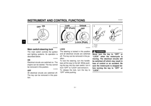
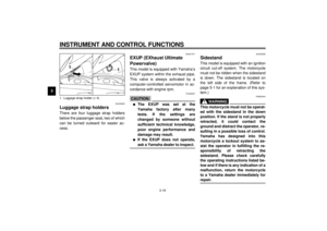
Lights switch
Turning the light switch to “ ”,
turns on the auxiliary light, meter lights
and taillight. Turning the light switch to
“ ” turns the headlight on also.
EAU00138
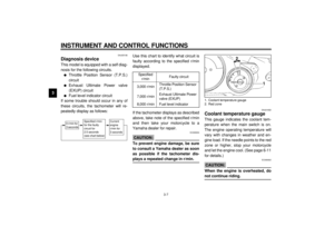
Engine stop switch
The engine stop switch is a safety de-
vice for use in an emergency such as
when the motorcycle overturns or if
trouble occurs in the throttle system.
Turn the switch to “ ” to start the en-
gine. In case of emergency, turn the
switch to “ ” to stop the engine.
EAU00141
Start switch “ ”
The starter motor cranks the engine
when pushing the start switch.
EC000005
CAUTION:@ See starting instructions prior to
starting the engine. @
EAU00153
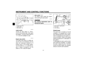
Clutch leverThe clutch lever is located on the left
handlebar. It is equipped with a clutch
lever adjusting dial and a clutch switch,
which is integrated into the ignition cir-
cuit cut-off system. (Refer to the engine
starting procedures for a description of
this system.)
To disengage the clutch, pull the clutch
lever toward the handlebar. To engage
the clutch, release the lever. The lever
should be pulled rapidly and released
slowly for smooth clutch operation.
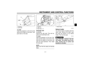
1. Engine stop switch
2. Lights switch
3. Start switch “ ”
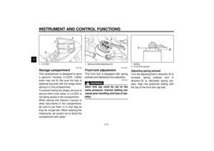
1. Lever position adjusting dial
2. Arrow mark
a. Lever distance
E_4sv_Functions.fm Page 9 Tuesday, August 31, 1999 3:42 PM
Page 24 of 103

INSTRUMENT AND CONTROL FUNCTIONS
3-10
3 To adjust the distance between the
clutch lever and the handlebar grip,
turn the clutch adjusting dial while
pushing the lever forward. Make sure
the setting on the clutch lever adjusting
dial is aligned with the arrow mark.
EAU00157
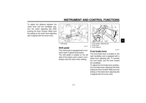
Shift pedalThis motorcycle is equipped with a con-
stant-mesh 5-speed transmission.
The shift pedal is located on the left
side of the engine and is used in com-
bination with the clutch when shifting.
EAU00161
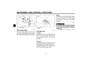
Front brake leverThe front brake lever is located on the
right handlebar and is equipped with a
brake lever adjusting dial. To activate
the front brake, pull the lever toward
the handlebar.
To adjust the front brake lever position,
turn the brake lever adjusting dial while
pulling the lever forward. Make sure the
setting on the brake lever adjusting dial
is aligned with the arrow mark.
1. Shift pedal
1. Lever position adjusting dial
2. Arrow mark
a. Lever distance
E_4sv_Functions.fm Page 10 Tuesday, August 31, 1999 3:42 PM