Page 25 of 91
INSTRUMENT AND CONTROL FUNCTIONS
3-11
3
EAU01636
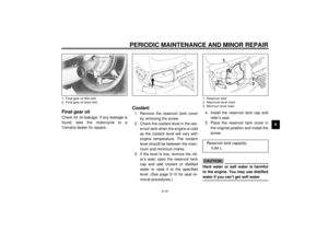
Helmet holdersThere are two helmet holders under the
rider seat. To secure a helmet on the
right side holder, simply hook the buck-
le of the helmet strap over the holder
and close the seat securely.To secure a helmet on the left side
holder, use the helmet holding cable lo-
cated beside the tool kit. Pass the ca-
ble through the buckle on the helmet
strap, then place both cable loops over
the holder and close the seat securely.
EW000031
WARNING
@ Never ride with a helmet secured in
the seat lock. The helmet may hit ob-
jects, causing loss of control and
possibly an accident. @
1. Helmet holder (´ 2)
1. Helmet holding cable
E_4YP_Functions.fm Page 11 Wednesday, October 6, 1999 10:03 AM
Page 26 of 91

INSTRUMENT AND CONTROL FUNCTIONS
3-12
3
EAU01605
Adjusting front fork preloadEach fork leg is equipped with an air
valve to adjust the spring preload. The
spring preload is adjusted by changing
the air pressure in each fork leg. In-
creasing the air pressure increases the
spring preload, decreasing air pressure
decreases spring preload. Special
equipment is required to adjust the air
pressure in the front fork. Have your
Yamaha dealer make this adjustment.
NOTE:@ In order to check or adjust the air pres-
sure, the motorcycle must be elevated
so the front wheel is not in contact with
the ground. @
EW000037
WARNING
@ Each fork leg must be set to the
same pressure. Uneven setting can
cause poor handling and loss of sta-
bility. @
EC000012
CAUTION:@ Never exceed the maximum pres-
sure, or oil seal damage may occur. @
1. Air valve
Minimum/standard air pressure
setting:
Zero
Maximum air pressure setting:
50 kPa (0.50 kg/cm
2, 0.50 bar)
E_4YP_Functions.fm Page 12 Wednesday, October 6, 1999 10:03 AM
Page 27 of 91
INSTRUMENT AND CONTROL FUNCTIONS
3-13
3
EAU01694
Adjusting rear shock
absorber preloadThis shock absorber is equipped with a
spring preload adjusting nut. Use the
special wrench located in the owner’s
tool kit to adjust the spring preload.1. Loosen the locknut.2. Turn the adjusting nut in
direction
a to increase spring pre-
load and in direction
b to de-
crease spring preload. The spring
preload is determined by the
spring set length.
Shortening the spring set length
increases spring preload, length-
ening the spring set length de-
creases spring preload.1. Special wrench
1. Locknut
2. Adjusting nut
A. Distance “A”
E_4YP_Functions.fm Page 13 Wednesday, October 6, 1999 10:03 AM
Page 28 of 91

INSTRUMENT AND CONTROL FUNCTIONS
3-14
3
EC000015
CAUTION:@ Never attempt to turn an adjuster
beyond the maximum or minimum
setting. @3. Tighten the locknut to the speci-
fied torque.
EC000018
CAUTION:@ Always tighten the locknut against
the spring adjusting nut and tighten
the locknut to the specified torque. @
EAU00315
WARNING
@ This shock absorber contains high-
ly pressurized nitrogen gas. Read
and understand the following infor-
mation before handling the shock
absorber. The manufacturer cannot
be held responsible for property
damage or personal injury that may
result from improper handling.l
Do not tamper with or attempt to
open the cylinder assembly.
l
Do not subject the shock ab-
sorber to an open flame or other
high heat source. This may
cause the unit to explode due to
excessive gas pressure.
l
Do not deform or damage the
cylinder in any way. Cylinder
damage will result in poor
damping performance.
l
Take your shock absorber to a
Yamaha dealer for any service.
@
Spring preload:
Minimum (soft):
Distance “A” = 48.5 mm
Standard:
Distance “A” = 45.5 mm
Maximum (hard):
Distance “A” = 40.5 mm
Tightening torque:
Locknut:
25 Nm (2.5 m·kg)
E_4YP_Functions.fm Page 14 Wednesday, October 6, 1999 10:03 AM
Page 29 of 91

INSTRUMENT AND CONTROL FUNCTIONS
3-15
3
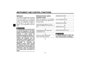
EAU00330
SidestandThis model is equipped with an ignition
circuit cut-off system. The motorcycle
must not be ridden when the sidestand
is down. The sidestand is located on
the left side of the frame. (Refer to
page 5-1 for an explanation of this sys-
tem.)
EW000044
WARNING
@ This motorcycle must not be operat-
ed with the sidestand in the down
position. If the stand is not properly
retracted, it could contact the
ground and distract the operator, re-
sulting in a possible loss of control.
Yamaha has designed into this
motorcycle a lockout system to as-
sist the operator in fulfilling the re-
sponsibility of retracting the
sidestand. Please check carefully
the operating instructions listed be-
low and if there is any indication of a
malfunction, return the motorcycle
to a Yamaha dealer immediately for
repair. @
EAU00331
Sidestand/clutch switch
operation checkCheck the operation of the sidestand
switch and clutch switch against the in-
formation below.CD-11E
CD-11E
EW000045
WARNING
@ If improper operation is noted, con-
sult a Yamaha dealer immediately. @
TURN THE MAIN SWITCH TO “ON”
AND THE ENGINE STOP SWITCH TO
“”.TRANSMISSION IS IN GEAR AND
SIDESTAND IS UP.PULL IN CLUTCH LEVER AND
PUSH THE START SWITCH.
ENGINE WILL START.SIDESTAND IS DOWN.ENGINE WILL STALL.SIDESTAND SWITCH IS OK.CLUTCH SWITCH IS OK.
E_4YP_Functions.fm Page 15 Wednesday, October 6, 1999 10:03 AM
Page 30 of 91
4
PRE-OPERATION CHECKS
Pre-operation check list ...................................................................... 4-1
E_4YP_PreopTOC.fm Page 1 Wednesday, October 6, 1999 10:04 AM
Page 31 of 91

4-1
4
EAU01114
4-PRE-OPERATION CHECKSOwners are personally responsible for their vehicle’s condition. Your motorcycle’s vital functions can start to deteriorate
quickly and unexpectedly, even if it remains unused (for instance, if it is exposed to the elements). Any damage, fluid leak or
loss of tire pressure could have serious consequences. Therefore, it is very important that, in addition to a thorough visual in-
spection, you check the following points before each ride.
EAU00340
PRE-OPERATION CHECK LIST
ITEM CHECKS PAGE
Front brake• Check operation, fluid level and vehicle for fluid leakage.
• Fill with DOT 4 brake fluid if necessary.
6-17 ~ 6-21
Rear brake• Check operation, fluid level and vehicle for fluid leakage.
• Fill with DOT 4 brake fluid if necessary.
Clutch• Check operation, fluid level and vehicle for fluid leakage.
• Fill with DOT 4 brake fluid if necessary.6-16
Throttle grip and housing• Check for smooth operation.
• Lubricate if necessary.6-12
Engine oil• Check oil level.
• Fill with oil if necessary.6-7 ~ 6-9
Coolant reservoir tank• Check coolant level.
• Fill with coolant if necessary.6-10 ~ 6-11
Final gear oil• Check vehicle for leakage. 6-10
Wheels and tires• Check tire pressure, wear and for damage. 6-13 ~ 6-16
Brake and shift pedal
shafts• Check for smooth operation.
• Lubricate if necessary.6-21
Brake and clutch lever
pivots• Check for smooth operation.
• Lubricate if necessary.6-22
Sidestand pivot• Check for smooth operation.
• Lubricate if necessary.6-22
E_4YP_Preop.fm Page 1 Wednesday, October 6, 1999 10:04 AM
Page 32 of 91
PRE-OPERATION CHECKS
4-2
4
NOTE:Pre-operation checks should be made each time the motorcycle is used. Such an inspection can be thoroughly accom-
plished in a very short time; and the added safety it assures is more than worth the time involved.
WARNING
If any item in the PRE-OPERATION CHECK is not working properly, have it inspected and repaired before operating
the motorcycle.Chassis fasteners• Make sure that all nuts, bolts and screws are properly tightened.
• Tighten if necessary.—
Fuel• Check fuel level.
• Fill with fuel if necessary.3-7 ~ 3-8
Lights, signals and
switches• Check for proper operation. 6-27 ~ 6-28 ITEM CHECKS PAGE
E_4YP_Preop.fm Page 2 Wednesday, October 6, 1999 10:04 AM