Page 25 of 101
3-9
INSTRUMENT AND CONTROL FUNCTIONS
1
2
3
4
5
6
7
8
9
1. Starter (choke) “ ”
EAU02973
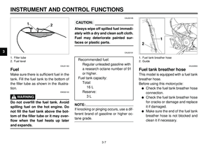
Starter (choke) “ ”
Starting a cold engine requires a richer
air-fuel mixture. A separate starter cir-
cuit supplies this mixture.
Move in direction
a
to turn on the
starter (choke).
Move in direction
b
to turn off the
starter (choke).
ECA00038
CAUTION:
Do not use the starter (choke) for
more than 3 minutes as the exhaust
pipe may discolor from excessive
heat. Also, longer use of the starter
(choke) will cause afterburning. If
afterburning occurs, turn off the
starter (choke).
XVS650
1. Nut
EAU01889
Seats (for XVS650)
Passenger seat
To remove
Remove the nut and pull the seat up-
ward.
Page 26 of 101
3-10
INSTRUMENT AND CONTROL FUNCTIONS
1
2
3
4
5
6
7
8
9
XVS650
1. Bolt (
´
2)
2. Seat holder
3. Projection
To install
Insert the projection on the front of the
seat into the seat holder and install the
nut.
XVS650
1. Seat holder
2. Projection
Rider seat
To remove
1. Remove the passenger seat.
2. Remove the two bolts and pull the
seat upward.
To install1. Insert the projection on the front of
the seat into the seat holder and
install the bolts.
2. Install the passenger seat.NOTE:
Make sure that the seats are securely
fitted.
Page 27 of 101
3-11
INSTRUMENT AND CONTROL FUNCTIONS
1
2
3
4
5
6
7
8
9
XVS650A
1. Bolt
EAU01888
Seats (for XVS650A)
Passenger seat
To remove
Remove the bolt and pull the seat up-
ward.
XVS650A
1. Seat holder
2. Projection (
´
2)
To install
Insert the projections on the front of the
seat into the holder and install the bolt.
XVS650A
1. Bolt
Rider seat
To remove
1. Remove the passenger seat.
2. Remove the bolt and pull the seat
upward.
Page 28 of 101
3-12
INSTRUMENT AND CONTROL FUNCTIONS
1
2
3
4
5
6
7
8
9
XVS650A
1. Seat holder
2. Projection
To install
1. Insert the projection on the front of
the seat into the holder and install
the bolt.
2. Install the passenger seat.NOTE:
Make sure that the seats are securely
fitted.
1. Helmet holder
EAU00260
Helmet holder
To open the helmet holder, insert the
key in the lock and turn it as shown. To
lock the helmet holder, replace the
holder in its original position.
EW000030
WARNING
Never ride with a helmet in the hel-
met holder. The helmet may hit ob-
jects, causing loss of control andpossibly an accident.
Page 29 of 101
3-13
INSTRUMENT AND CONTROL FUNCTIONS
1
23
4
5
6
7
8
9
1. Compartment cover
2. Lock
EAU01869
Storage compartmentThe storage compartment is located
on the left side of the motorcycle.
To open
Slide the lock cover open, insert the
key in the lock and turn it clockwise.
Then, pull the storage compartment
cover out as shown.
1. Storage compartmentTo close
Place the storage compartment cover
in its original position as shown. Then,
turn the key counterclockwise and re-
move it. Close the lock cover.
Page 30 of 101

3-14
INSTRUMENT AND CONTROL FUNCTIONS
1
23
4
5
6
7
8
9
1. Position indicator
2. Adjusting ring
3. Extension bar
4. Special wrench
EAU00299*
Rear shock absorber adjust-
mentThis shock absorber is equipped with a
spring preload adjuster. Adjust spring
preload as follows:
1. Remove the passenger seat and
rider seat. (See page 3-9 for re-
moval procedures.)2. Use the special wrench and the
extension bar in the owner’s tool
kit to turn the adjusting ring. Turn
the adjusting ring in direction a
to increase spring preload and in
direction b to decrease spring
preload. Make sure that the ap-
propriate notch in the adjusting
ring is aligned with the position in-
dicator on the rear shock absorb-
er.
COPY CI-15ECI-15E3. Install the seats.
SoftStan-
dardHard
Adjusting
position12 3 4567
EAU00315
WARNING
This shock absorber contains high-
ly pressurized nitrogen gas. Read
and understand the following infor-
mation before handling the shock
absorber. The manufacturer cannot
be held responsible for property
damage or personal injury that may
result from improper handling.l
Do not tamper with or attempt
to open the cylinder assembly.
l
Do not subject the shock ab-
sorber to an open flame or oth-
er high heat source. This may
cause the unit to explode due
to excessive gas pressure.
l
Do not deform or damage the
cylinder in any way. Cylinder
damage will result in poor
damping performance.
l
Take your shock absorber to aYamaha dealer for any service.
Page 31 of 101

EAU01172
Luggage strap holdersThere is a luggage strap holder locat-
ed at each passenger footrest.
EAU00330
Sides")
3-15
INSTRUMENT AND CONTROL FUNCTIONS
1
23
4
5
6
7
8
9
1. Luggage strap holder (´ 2)
EAU01172
Luggage strap holdersThere is a luggage strap holder locat-
ed at each passenger footrest.
EAU00330
SidestandThis model is equipped with an ignition
circuit cut-off system. The motorcycle
must not be ridden when the sidestand
is down. The sidestand is located on
the left side of the frame. (Refer to
page 5-1 for an explanation of this sys-
tem.)
EW000044
WARNING
This motorcycle must not be operat-
ed with the sidestand in the down
position. If the stand is not properly
retracted, it could contact the
ground and distract the operator,
resulting in a possible loss of con-
trol. Yamaha has designed into this
motorcycle a lockout system to as-
sist the operator in fulfilling the re-
sponsibility of retracting the
sidestand. Please check carefully
the operating instructions listed be-
low and if there is any indication of
a malfunction, return the motor-
cycle to a Yamaha dealer immedi-ately for repair.
Page 32 of 101
3-16
INSTRUMENT AND CONTROL FUNCTIONS
1
23
4
5
6
7
8
9
EAU00331
Sidestand/clutch switch
operation checkCheck the operation of the sidestand
switch and clutch switch against the in-
formation below.COPY CD-11ECD-11ETURN THE MAIN SWITCH TO “ON”
AND THE ENGINE STOP SWITCH TO
“”.TRANSMISSION IS IN GEAR AND
SIDESTAND IS UP.PULL IN CLUTCH LEVER AND
PUSH THE START SWITCH.ENGINE WILL START.CLUTCH SWITCH IS OK.
CD-11E
EW000045
WARNING
If improper operation is noted, con-sult a Yamaha dealer immediately.SIDESTAND IS DOWN.ENGINE WILL STALL.SIDESTAND SWITCH IS OK.


 “ ”
EAU02973
Starter (choke) “ ”
Starting a cold engine requires a richer
air-fuel mixture. A separate starte")

2. Seat holder
3. Projection
To install
Insert the projection on the front of the
seat into the seat holder and")

Passenger seat
To remove
Remove the bolt and pull the seat up-
ward.
XVS650A
1. Seat ho")


