Page 17 of 101

3-1
INSTRUMENT AND CONTROL FUNCTIONS
1
23
4
5
6
7
8
9
EAU00029
Main switch/Steering lock
The main switch controls the ignition
and lighting systems. Its operation is
described below.
EAU00036
ON
Electrical circuits are switched on. The
engine can be started. The key cannot
be removed in this position.
EAU00038
OFF
All electrical circuits are switched off.
The key can be removed in this posi-
tion.
EAU00040
LOCK
The steering is locked in this position
and all electrical circuits are switched off.
The key can be removed in this posi-
tion. To lock the steering, turn the han-
dlebars all the way to the left. While
pushing the key into the main switch,
turn it from “OFF” to “LOCK” and re-
move it. To release the lock, turn the
key to “OFF” while pushing.
EW000016
WARNING
Never turn the key to “OFF” or
“LOCK” when the motorcycle is
moving. The electrical circuits will
be switched off which may result in
loss of control or an accident. Be
sure the motorcycle is stopped be-
fore turning the key to “OFF” or
“LOCK”.
1. Push
2. Turn
EAU00044
(Parking)
The steering is locked in this position
and the taillight comes on, but all other
circuits are off. The key can be re-
moved in this position.
To use the parking position, first lock
the steering, then turn the key to “ ”.
Do not use this position for an extend-
ed length of time as the battery may
discharge.
EAU00027
Page 18 of 101

3-2
INSTRUMENT AND CONTROL FUNCTIONS
1
2
3
4
5
6
7
8
9
1. High beam indicator light “ ”
2. Turn indicator light “ ”
3. Neutral indicator light “ ”
4. Engine trouble indicator light “ ”
EAU00056
Indicator lights
EAU00057
1. Turn indicator light “ ”
This indicator flashes when the turn
switch is moved to the left or right.
EAU00061
2. Neutral indicator light “ ”
This indicator comes on when the
transmission is in neutral.
EAU00063
3. High beam indicator light “ ”
This indicator comes on when the
headlight high beam is used.
EAU00091
4. Engine trouble indicator light
“”
This indicator light will come on or flash
if trouble occurs in a monitoring circuit.
In such a case, take the motorcycle to
a Yamaha dealer to have the self-diag-
nostic systems checked.
1. Reset knob
2. Speedometer
3. Odometer
4. Trip odometer
EAU00095
Speedometer
The speedometer shows riding speed.
This speedometer is equipped with an
odometer and trip odometer. The trip
odometer can be reset to “0” with the
reset knob. Use the trip odometer to
estimate how far you can ride on a
tank of fuel. This information will en-
able you to plan fuel stops in the fu-
ture.
Page 19 of 101
3-3
INSTRUMENT AND CONTROL FUNCTIONS
1
2
3
4
5
6
7
8
9
EAU00109
Antitheft alarm (optional)
An antitheft alarm can be equipped to
this motorcycle. Consult your Yamaha
dealer to obtain and install the alarm.
1. Turn signal switch
2. Pass switch “ ”
3. Dimmer switch
4. Horn switch “ ”
EAU00118
Handlebar switches
EAU00127
Turn signal switch
To signal a right-hand turn, push the
switch to “ ”. To signal a left-hand
turn, push the switch to “ ”. Once
the switch is released it will return to
the center position. To cancel the sig-
nal, push the switch in after it has re-
turned to the center position.
EAU00119
Pass switch “ ”
Press the switch to operate the pass-
ing light.
EAU00121
Dimmer switch
Turn the switch to “ ” for the high
beam and to “ ” for the low beam.
EAU00129
Horn switch “ ”
Press the switch to sound the horn.
Page 20 of 101
3-4
INSTRUMENT AND CONTROL FUNCTIONS
1
2
3
4
5
6
7
8
9
1. Start switch “ ”
2. Engine stop switch
3. Lights switch
EAU00143
Start switch “ ”
The starter motor cranks the engine
when pushing the start switch.
EC000005
CAUTION:
See starting instructions prior to
starting the engine.
EAU00138
Engine stop switch
The engine stop switch is a safety de-
vice for use in an emergency such as
when the motorcycle overturns or if
trouble occurs in the throttle system.
Turn the switch to “ ” to start the en-
gine. In case of emergency, turn the
switch to “ ” to stop the engine.
EAU00134
Lights switch
Turning the light switch to “ ”,
turns on the auxiliary light, meter lights
and taillight. Turning the light switch to
“ ”, turns the headlight on also.
Page 21 of 101
3-5
INSTRUMENT AND CONTROL FUNCTIONS
1
2
3
4
5
6
7
8
9
EAU00152
Clutch lever
The clutch lever is located on the left
handlebar, and the ignition circuit cut-
off system is incorporated in the clutch
lever holder. Pull the clutch lever to the
handlebar to disengage the clutch, and
release the lever to engage the clutch.
The lever should be pulled rapidly and
released slowly for smooth clutch op-
eration. (Refer to the engine starting
procedures for a description of the ig-
nition circuit cut-off system.)
EAU00157
Shift pedal
This motorcycle is equipped with a
constant-mesh 5-speed transmission.
The shift pedal is located on the left
side of the engine and is used in com-
bination with the clutch when shifting.
EAU00158
Front brake lever
The front brake lever is located on the
right handlebar. Pull it toward the han-
dlebar to apply the front brake.
Page 22 of 101
3-6
INSTRUMENT AND CONTROL FUNCTIONS
1
2
3
4
5
6
7
8
9
EAU00162
Rear brake pedal
The rear brake pedal is on the right
side of the motorcycle. Press down on
the brake pedal to apply the rear
brake.
EAU00167
Fuel tank cap
To open
Insert the key and turn it 1/4 turn clock-
wise. The lock will be released and the
cap can be opened.
To close
Push the tank cap into position with the
key inserted. To remove the key, turn it
counterclockwise to the original posi-
tion.
NOTE:
This tank cap cannot be closed unless
the key is in the lock. The key cannot
be removed if the cap is not locked
properly.
EW000023
WARNING
Be sure the cap is properly installed
and locked in place before riding
the motorcycle.
Page 23 of 101

3-7
INSTRUMENT AND CONTROL FUNCTIONS
1
2
3
4
5
6
7
8
9
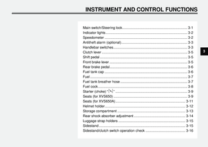
1. Filler tube
2. Fuel level
EAU01183
Fuel
Make sure there is sufficient fuel in the
tank. Fill the fuel tank to the bottom of
the filler tube as shown in the illustra-
tion.
EW000130
WARNING
Do not overfill the fuel tank. Avoid
spilling fuel on the hot engine. Do
not fill the fuel tank above the bot-
tom of the filler tube or it may over-
flow when the fuel heats up later
and expands.
EAU00185
CAUTION:
Always wipe off spilled fuel immedi-
ately with a dry and clean soft cloth.
Fuel may deteriorate painted sur-
faces or plastic parts.
EAU00191
NOTE:
If knocking or pinging occurs, use a dif-
ferent brand of gasoline or higher oc-
tane grade.Recommended fuel:
Regular unleaded gasoline with
a research octane number of 91
or higher.
Fuel tank capacity:
Total:
16 L
Reserve:
3 L
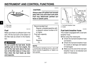
1. Fuel tank breather hose
2. Guide
EAU02955
Fuel tank breather hose
This model is equipped with a fuel tank
breather hose.
Before using this motorcycle:
l
Check the fuel tank breather hose
connection.
l
Check the fuel tank breather hose
for cracks or damage and replace
it if damaged.
l
Make sure the end of the fuel tank
breather hose is not blocked and
clean it if necessary.
Page 24 of 101
3-8
INSTRUMENT AND CONTROL FUNCTIONS
1
2
3
4
5
6
7
8
9
Off position
1. Arrow mark positioned over “OFF”
EAU02969
Fuel cock
The fuel cock supplies fuel from the
tank to the carburetors while filtering it
also.
The fuel cock has three positions,
which should be set as shown in the il-
lustrations.
OFF
With the fuel cock in this position, fuel
will not flow. Always set the fuel cock to
this position when the engine is not
running.
Normal position
1. Arrow mark positioned over “ON”
ON
With the fuel cock in this position, fuel
flows to the carburetors. Set the fuel
cock to this position when starting the
engine and while riding.Reserve position
1. Arrow mark positioned over “RES”
RES
This indicates reserve. If you run out of
fuel while riding, set the fuel cock to
this position. Fill the tank at the first op-
portunity. Be sure to set the fuel cock
back to “ON” after refueling!


An antitheft alarm can be equipped to
this motorcycle. Consult your Yamaha
dealer to obtain and insta")


