Page 25 of 95
INSTRUMENT AND CONTROL FUNCTIONS
3-11
3
EAU03050
Fuel cockThe fuel cock supplies fuel from the
tank to the carburetor while filtering it
also.
The fuel cock has three positions:
OFF
With the lever in this position, fuel will
not flow. Always return the lever to this
position when the engine is not run-
ning.ON
With the lever in this position, fuel flows
to the carburetor. Normal riding is done
with the lever in this position.RES
This indicates reserve. If you run out of
fuel while riding, move the lever to this
position. Fill the tank at the first oppor-
tunity. Be sure to set the lever back to
“ON” after refueling!OFF: closed position
ON: normal position
RES : reserve position
E_5ja_Functions.fm Page 11 Saturday, October 16, 1999 10:10 AM
Page 26 of 95
INSTRUMENT AND CONTROL FUNCTIONS
3-12
3
EAU03032
Starter (choke) knobStarting a cold engine requires a richer
air-fuel mixture, which is supplied by
the starter (choke).
Move the knob in direction
a to turn on
the starter (choke).
Move the knob in direction
b to turn off
the starter (choke).
EAU01214*
Steering lockOn the right side of the headpipe, there
is a place to lock the steering with a
padlock. Turn the handlebars to align
the holes in the two brackets and lock
the steering with a suitable padlock.
E_5ja_Functions.fm Page 12 Saturday, October 16, 1999 10:10 AM
Page 27 of 95
INSTRUMENT AND CONTROL FUNCTIONS
3-13
3
EAU01737
Rider seatTo remove
Insert the key into the main switch and
turn it counterclockwise to the “OPEN”
position. Then, remove the seat by pull-
ing it upward.NOTE:@ Do not push inward when turning the
key. @
To install
Insert the projection on the rear of the
seat into the holder, then push the front
of the seat downward until it locks and
remove the key from the main switch.NOTE:@ Make sure the seat is securely installed
before riding the motorcycle. @
EAU01819*
Helmet holderThe helmet holder is located under the
rider seat.
Remove the rider seat and hook the
helmet on the helmet holder. Then, in-
stall the seat.
EW000030
WARNING
@ Never ride with a helmet in the hel-
met holder. The helmet may hit ob-
jects, causing loss of control and
possibly an accident. @
1. Projection
2. Seat holder
1. Helmet holder
E_5ja_Functions.fm Page 13 Saturday, October 16, 1999 10:10 AM
Page 28 of 95
INSTRUMENT AND CONTROL FUNCTIONS
3-14
3
EAU01694
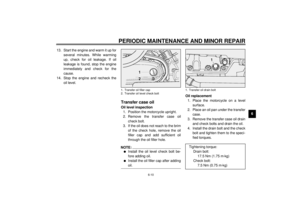
Adjusting rear shock
absorber preloadThis shock absorber is equipped with a
spring preload adjusting nut. Use the
special wrench located in the owner’s
tool kit to adjust the spring preload.
1. Loosen the locknut.2. Turn the adjusting nut in
direction
a to increase spring pre-
load and in direction
b to de-
crease spring preload. The spring
preload is determined by the
spring set length.
Shortening the spring set length
increases spring preload, length-
ening the spring set length de-
creases spring preload.
EC000015
CAUTION:@ Never attempt to turn an adjuster
beyond the maximum or minimum
setting. @
1. Locknut
2. Adjusting nut
1. Special wrench
A. Distance “A”Spring preload:
Minimum (soft):
Distance “A” = 42.5 mm
Standard:
Distance “A” = 42.5 mm
Maximum (hard):
Distance “A” = 51.5 mm
E_5ja_Functions.fm Page 14 Saturday, October 16, 1999 10:10 AM
Page 29 of 95

INSTRUMENT AND CONTROL FUNCTIONS
3-15
33. Tighten the locknut to the speci-
fied torque.
EC000018
CAUTION:@ Always tighten the locknut against
the spring adjusting nut and tighten
the locknut to the specified torque. @
EAU00315
WARNING
@ This shock absorber contains high-
ly pressurized nitrogen gas. Read
and understand the following infor-
mation before handling the shock
absorber. The manufacturer cannot
be held responsible for property
damage or personal injury that may
result from improper handling.l
Do not tamper with or attempt to
open the cylinder assembly.
l
Do not subject the shock ab-
sorber to an open flame or other
high heat source. This may
cause the unit to explode due to
excessive gas pressure.
l
Do not deform or damage the
cylinder in any way. Cylinder
damage will result in poor
damping performance.
l
Take your shock absorber to a
Yamaha dealer for any service.
@
EAU00330
SidestandThis model is equipped with an ignition
circuit cut-off system. The motorcycle
must not be ridden when the sidestand
is down. The sidestand is located on
the left side of the frame. (Refer to
page 5-1 for an explanation of this sys-
tem.)
EW000044
WARNING
@ This motorcycle must not be operat-
ed with the sidestand in the down
position. If the stand is not properly
retracted, it could contact the
ground and distract the operator, re-
sulting in a possible loss of control.
Yamaha has designed into this
motorcycle a lockout system to as-
sist the operator in fulfilling the re-
sponsibility of retracting the
sidestand. Please check carefully
the operating instructions listed be-
low and if there is any indication of a
malfunction, return the motorcycle
to a Yamaha dealer immediately for
repair. @
Tightening torque:
Locknut:
35 Nm (3.5 m·kg)
E_5ja_Functions.fm Page 15 Saturday, October 16, 1999 10:10 AM
Page 30 of 95
INSTRUMENT AND CONTROL FUNCTIONS
3-16
3
EAU00331
Sidestand/clutch switch
operation checkCheck the operation of the sidestand
switch and clutch switch against the in-
formation below.CD-11E
CD-11E
EW000045
WARNING
@ If improper operation is noted, con-
sult a Yamaha dealer immediately. @
TURN THE MAIN SWITCH TO “ON”
AND THE ENGINE STOP SWITCH TO
“”.TRANSMISSION IS IN GEAR AND
SIDESTAND IS UP.PULL IN CLUTCH LEVER AND
PUSH THE START SWITCH.ENGINE WILL START.SIDESTAND IS DOWN.CLUTCH SWITCH IS OK.
ENGINE WILL STALL.SIDESTAND SWITCH IS OK.
E_5ja_Functions.fm Page 16 Saturday, October 16, 1999 10:10 AM
Page 31 of 95
E_5ja_Functions.fm Page 17 Saturday, October 16, 1999 10:10 AM
Page 32 of 95
PRE-OPERATION CHECKS
4
Pre-operation check list ...................................................................... 4-1
E_5ja_PreopTOC.fm Page 1 Saturday, October 16, 1999 10:11 AM


 knobStarting a cold engine requires a richer
air-fuel mixture, which is supplied by
the starter (choke).
Move the knob in direction
a")


