Page 17 of 88

INSTRUMENT AND CONTROL FUNCTIONS
1
2
3
4
5
6
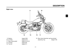
7
8
9
3-3
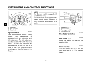
EAU00127Turn signal switch
To signal a right-hand turn, push
the switch to “6”. To signal a left-
hand turn, push the switch to
“4”. Once the switch is released
it will return to the center position.
To cancel the signal, push the
switch in after it has returned to
the center position.
EAU00129
Horn switch “*”
Press the switch to sound the horn.
1
2
3
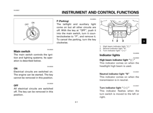
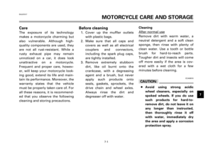
EAU00134Lights switch
Turning the light switch to “
'”,
turns on the auxiliary light, meter
lights and taillight. Turning the
light switch to “:” turns the head-
light on also.
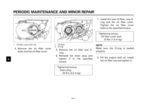
1. Engine stop switch
2. Lights switch
3. Start switch “$”
EAU00138Engine stop switch
The engine stop switch is a safety
device for use in an emergency
such as when the motorcycle over-
turns or if trouble occurs in the
throttle system. Turn the switch to
“#” to start the engine.
In case of emergency, turn the
switch to “$” to stop the engine.
EAU00143
Start switch “,“
The starter motor cranks the
engine when pushing the start
switch.
EC000005
cC
See starting instructions prior to
starting the engine.
5AJ-9-E3 (XV125S)<3.1E> 4/5/0 5:01 PM Page 15
Page 18 of 88
3-4
INSTRUMENT AND CONTROL FUNCTIONS
1
2
3
4
5
6
7
8
9
EAU00152Clutch lever
The clutch lever is located on the
left handlebar, and the ignition cir-
cuit cut-off system is incorporated
in the clutch lever holder. Pull the
clutch lever to the handlebar to dis-
engage the clutch, and release the
lever to engage the clutch. The
lever should be pulled rapidly and
released slowly for smooth clutch
operation. (Refer to the engine
starting procedures for a descrip-
tion of the ignition circuit cut-off
system.)
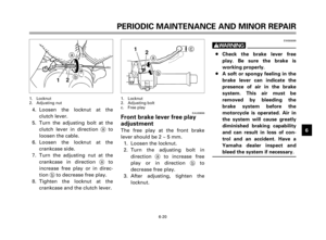
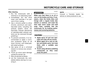
EAU00157Shift pedal
This motorcycle is equipped with a
constant-mesh 5-speed transmis-
sion.
The shift pedal is located on the
left side of the engine and is used
in combination with the clutch
when shifting.
N. Neutral
1. Shift pedal
EAU00158Front brake lever
The front brake lever is located on
the right handlebar. Pull it toward
the handlebar to apply the front
brake.
5
4
3
2
1 N
1
5AJ-9-E3 (XV125S)<3.1E> 4/5/0 5:01 PM Page 16
Page 19 of 88
INSTRUMENT AND CONTROL FUNCTIONS
1
2
3
4
5
6
7
8
9
3-5
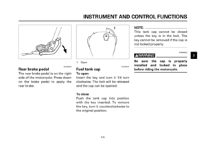
EAU00162Rear brake pedal
The rear brake pedal is on the right
side of the motorcycle. Press down
on the brake pedal to apply the
rear brake.
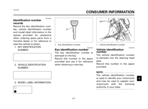
EAU00167Fuel tank cap
To open
Insert the key and turn it 1/4 turn
clockwise. The lock will be released
and the cap can be opened.
To close
Push the tank cap into position
with the key inserted. To remove
the key, turn it counterclockwise to
the original position.
1. Open
NOTE:
This tank cap cannot be closed
unless the key is in the lock. The
key cannot be removed if the cap is
not locked properly.
EW000023
w
Be sure the cap is properly
installed and locked in place
before riding the motorcycle.
1
5AJ-9-E3 (XV125S)<3.1E> 4/5/0 5:01 PM Page 17
Page 20 of 88
3-6
INSTRUMENT AND CONTROL FUNCTIONS
1
2
3
4
5
6
7
8
9
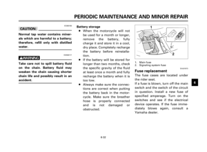
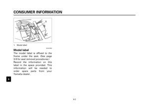
EAU01183Fuel
Make sure there is sufficient fuel in
the tank. Fill the fuel tank to the
bottom of the filler tube as shown
in the illustration.
EW000130
w
Do not overfill the fuel tank. Avoid
spilling fuel on the hot engine. Do
not fill the fuel tank above the bot-
tom of the filler tube or it may
overflow when the fuel heats up
later and expands.
1. Filler tube
2. Fuel level
EAU00185
cC
Always wipe off spilled fuel imme-
diately with a dry and clean soft
cloth. Fuel may deteriorate painted
surfaces or plastic parts.
EAU00191
NOTE:
If knocking or pinging occurs, use a
different brand of gasoline or high-
er octane grade.
1
2
Recommended fuel:
Regular unleaded gasoline
with a research octane
number of 91 or higher.
Fuel tank capacity:
Total:
9.5 L
Reserve:
2.6 L
5AJ-9-E3 (XV125S)<3.1E> 4/5/0 5:01 PM Page 18
Page 21 of 88
INSTRUMENT AND CONTROL FUNCTIONS
1
2
3
4
5
6
7
8
9
3-7
NOTE:
The fuel cock operates on vacuum
from the engine when set at “ON”
or “RES”. If the line connecting the
cock to the carburetor intake mani-
fold is not connected or has a leak,
the cock will not function properly.
EAU00208Fuel cock
The negative pressure fuel cock
supplies fuel from the tank to the
carburetor while filtering it also.
The fuel cock has the following
three positions:
ON
With the lever in this position, fuel
flows if the engine is running, but
stops if the engine is not running.
1. Arrow mark pointing to “ON”
RES
This indicates reserve. If you run
out of fuel while riding, move the
lever to “PRI”, start the engine,
then move the lever to “RES”. FILL
THE TANK AT THE FIRST OPPOR-
TUNITY. BE SURE TO MOVE THE
LEVER TO “ON” AFTER REFUEL-
ING.
1. Arrow mark pointing to “RES”
11
ONRES
5AJ-9-E3 (XV125S)<3.1E> 4/5/0 5:01 PM Page 19
Page 22 of 88

3-8
INSTRUMENT AND CONTROL FUNCTIONS
1
2
3
4
5
6
7
8
9PRI
This indicates prime. With the lever
in this position, fuel flows whether
the engine is running or not. If the
fuel tank is completely empty, refill
the tank and move the lever to
“PRI” to prime the carburetor.
Move the lever to “ON” after start-
ing the engine.
1. Arrow mark pointing to “PRI”
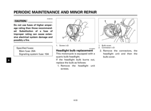
EAU02976Starter (choke) “1”
Starting a cold engine requires a
richer air-fuel mixture. A separate
starter circuit supplies this mixture.
Move in direction ato turn on the
starter (choke).
Move in direction bto turn off the
starter (choke).
1. Starter (choke) “1”
EAU02934Steering lock
To lock the steering
Turn the handlebars all the way to
the right and open the steering
lock cover.
Insert the key and turn it 1/8 turn
counterclockwise. Then, push the
key in while turning the handlebars
slightly to the left and turn the key
1/8 turn clockwise.
Check that the steering is locked,
remove the key and close the lock
cover.
To unlock the steering
Insert the key, push it in and turn it
1/8 turn counterclockwise so that it
moves out. Then, release and
remove the key.
1. Steering lock
1
1a
b1
PRI
5AJ-9-E3 (XV125S)<3.1E> 4/5/0 5:01 PM Page 20
Page 23 of 88
INSTRUMENT AND CONTROL FUNCTIONS
1
2
3
4
5
6
7
8
9
3-9
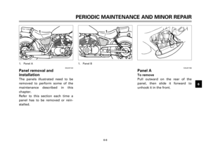
EAU03020Seat
To remove
1. Remove panels A and B. (See
page 6-6 for panel removal
and installation procedures.)
2. Remove the rider seat bolts
and lift the seat upward.
1. Bolt (´2)
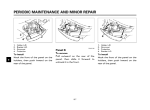
To install
1. Insert the projection on the
front of the rider seat into the
seat holder, then tighten the
seat bolts.
2. Install the panels.
NOTE:
Make sure that the seat is securely
fitted.
1. Projection
2. Seat holder
EAU00260Helmet holder
To open the helmet holder, insert
the key in the lock and turn it as
shown. To lock the helmet holder,
replace the holder in its original
position.
EW000030
w
Never ride with a helmet in the
helmet holder. The helmet may hit
objects, causing loss of control
and possibly an accident.
1. Helmet holder
2. Open
1
1
22 1
5AJ-9-E3 (XV125S)<3.1E> 4/5/0 5:01 PM Page 21
Page 24 of 88
3-10
INSTRUMENT AND CONTROL FUNCTIONS
1
2
3
4
5
6
7
8
9
1
2
3
4
5
b
a
1
EAU00300Rear shock absorber
adjustment
Each shock absorber is equipped
with a spring preload adjusting
ring. Adjust spring preload as fol-
lows.
Turn the adjusting ring in direction
ato increase spring preload and
in direction bto decrease spring
preload. Make sure that the appro-
priate notch in the adjusting ring is
aligned with the position indicator
on the rear shock absorber.
1. Position indicator
EW000040
w
Always adjust each shock
absorber to the same setting.
Uneven adjustment can cause
poor handling and loss of stability.
EAU00330Sidestand
This model is equipped with an
ignition circuit cut-off system. The
motorcycle must not be ridden
when the sidestand is down. The
sidestand is located on the left side
of the frame. (Refer to page 5-1 for
an explanation of this system.)
SoftStan-
Harddard
Adjusting
12345
position
5AJ-9-E3 (XV125S)<3.1E> 4/5/0 5:01 PM Page 22


2. Remove the rider seat bolts
and")
